Extending the Cisco SD-WAN Fabric into Azure with Cisco Cloud onRamp for Multi-Cloud
Available Languages
Bias-Free Language
The documentation set for this product strives to use bias-free language. For the purposes of this documentation set, bias-free is defined as language that does not imply discrimination based on age, disability, gender, racial identity, ethnic identity, sexual orientation, socioeconomic status, and intersectionality. Exceptions may be present in the documentation due to language that is hardcoded in the user interfaces of the product software, language used based on RFP documentation, or language that is used by a referenced third-party product. Learn more about how Cisco is using Inclusive Language.
- US/Canada 800-553-2447
- Worldwide Support Phone Numbers
- All Tools
 Feedback
 Feedback
Define – Cisco Cloud onRamp for Multi-Cloud Introduction
Deploy - Cisco Cloud onRamp for Multi-Cloud with Azure
Process: Deploy a Cloud Gateway with Cisco Cloud onRamp for Multi-Cloud
Process: Map Host vNets to the Cloud Gateway
Operate - Cisco Cloud onRamp for Multi-Cloud
Process: Modifying an Existing Cloud Gateway Deployment (Optional)
Process: Adding an Inbound Route Map to Filter BGP Routes from Azure (Optional)
Process: Monitor Cisco Cloud onRamp for Multi-Cloud
Appendix A: Changes from Previous Versions
Appendix B: Hardware and Software Used for Validation
Appendix C: Cisco Catalyst 8000v Router Configuration Template Summary
Appendix D: Cloud Gateway Catalyst 8000v SD-WAN Edge Router CLI Configurations
Appendix E: Azure Prerequisites
Process: Check Azure Subscription Permissions
Process: Register an Application with Azure Active Directory (AD)
Process: Assign a Role to the Application
Appendix F: Integration with a Service vNet Hosting a Load-Balancer and Firewalls
About the Guide
The following IaaS public cloud providers are supported within the Cloud onRamp for Multi-Cloud feature within Cisco SD-WAN, as of Cisco vManage release 20.6.1:
● Amazon Web Services (AWS)
● Microsoft Azure
● Google Cloud Platform (GCP)
This guide is intended to provide technical guidance to design, deploy, and operate Cisco Cloud onRamp for Multi-Cloud with Azure. As of software release 17.6.1 / 20.6.1 Cisco Cloud onRamp for Multi-Cloud with Azure supports the instantiation of a single pair of Cisco Catalyst 8000v routers functioning as Network Virtualization Appliances (NVAs) within a virtual hub (vHub) within an Azure virtual WAN (vWAN).
| Technical Note |
| Cisco Cloud onRamp for Multi-Cloud with Azure does not support the instantiation of Cisco CSR 1000v or Cisco vEdge Cloud routers within the Azure vHub. Only Cisco Catalyst 8000v routers are supported. |
Because this deployment guide focuses primarily on Cisco Cloud onRamp for Multi-Cloud, the following are presumed:
● Cisco SD-WAN controllers (vManage, vBond, and vSmart) are already deployed with valid certificates.
● Cisco SD-WAN Edge devices at other branch and campus locations, as well as vSmart controllers have configurations – feature templates defined, device templates associated, and are in vManage mode.
● Cisco SD-WAN Edge devices at other branch and campus locations have been onboarded, have established control connections to the Cisco SD-WAN controllers, and have established data tunnels to other SD-WAN Edge devices across all available transports.
For more information on SD-WAN controller design and deployment, please refer to the Cisco SD-WAN Design Guide and the Cisco SD-WAN End-to-End Deployment Guide at the following URLs:
https://www.cisco.com/c/en/us/td/docs/solutions/CVD/SDWAN/cisco-sdwan-design-guide.html
https://www.cisco.com/c/dam/en/us/td/docs/solutions/CVD/SDWAN/SD-WAN-End-to-End-Deployment-Guide.pdf
This document contains four major sections:
● The Define section introduces the Cisco Cloud onRamp for Multi-Cloud feature and explains the overall solution, along with the benefits of deploying it.
● The Design section describes the Microsoft Azure vHub design used by Cisco Cloud onRamp for Multi-Cloud.
● The Deploy section is divided into two parts. The first part provides information regarding the prerequisites necessary for deploying Cisco Cloud onRamp for Multi-Cloud using Microsoft Azure as the IaaS public cloud provider. The second part discusses the automated deployment workflow of Cisco Cloud onRamp for Multi-Cloud with Azure.
● The Operate section shows additional operations and monitoring capabilities of Cisco Cloud onRamp for Multi-Cloud available through the Cisco vManage web-based graphical user interface (GUI).
Audience
The audience for this document includes network design engineers, network operations personnel, and security operations personnel who wish to implement Cisco SD-WAN secure virtual private network (VPN) connectivity from their private networks to one or more Microsoft Azure virtual networks (vNets).
Define – Cisco Cloud onRamp for Multi-Cloud Introduction
About the Solution
In a multi-cloud world, organizations realize the benefits of cloud computing services such as infrastructure as a service (IaaS) and have transitioned to either a hybrid model – using both on-prem and cloud-based data centers, or a cloud-first approach. IaaS public cloud providers, such as Microsoft Azure, allow organizations to prototype and deploy new applications more rapidly and cost-effectively. Instead of procuring, installing, and managing hardware – which could take months to accomplish – organizations can easily use the on-demand and scalable compute services in Azure as needed. This allows your organization to focus its resources on applications rather than on managing the data center and physical infrastructure.
With the use of IaaS, expenses shift from fixed costs for hardware, software, and data center infrastructure to variable costs based on the usage of compute resources and the amount of data transferred between the private data center, campus, and branch locations, and the IaaS public cloud provider. Hence, visibility into the usage of such resources for cost tracking and/or internal billing purposes is critical.
This guide focuses on how to implement secure network connectivity from one or more private network campus and/or branch locations to one or more Microsoft Azure virtual networks (vNets) using the Cisco SD-WAN Cloud onRamp for Multi-Cloud feature within Cisco vManage version 20.6.1. A vNet is an on-demand virtual network, logically isolated from other virtual networks within the Azure IaaS public cloud.
Design Overview
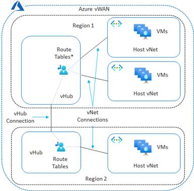
The Cisco Cloud onRamp for Multi-Cloud design extends the Cisco SD-WAN fabric to Azure through integration with a virtual WAN (vWAN). A vWAN is a global construct within Azure, representing the overall network deployment. Within the vWAN, there can be multiple virtual hubs (vHubs) per Azure region. A vHub is a special transit virtual network (vNet) managed by Azure. Since the vHub is completely managed by Azure, IP addresses are dynamically assigned by Azure based upon the address space specified when the vHub is instantiated. Azure automatically partitions the vHub IP address space for each of the subnets needed within the vHub itself.
Host vNets connect via vNet peering connections to a vHub within their Azure region. Host vNet connectivity between Azure regions can be provided through a combination of vHubs with vNet peering within each region, along with vHub-to-vHub peering between regions within the overall vWAN. The Azure vWAN design therefore provides for scalable connectivity between host vNets within an Azure region and between regions, as shown in the following figure.
With the Cisco Cloud onRamp for Multi-Cloud design, Cisco has partnered with Microsoft to provide the ability to instantiate a pair of Cisco Catalyst 8000v virtual form-factor SD-WAN routers functioning as Network Virtual Appliances (NVAs) directly within an Azure vHub. The combination of the vHub with an instantiated pair of Cisco Catalyst 8000v SD-WAN routers is referred to as a Cloud Gateway within this document.
The Cisco Cloud onRamp for Multi-Cloud feature provides the following benefits:
● Automated creation of the vWAN and vHub within Azure if necessary.
● Automation of the instantiation of the Catalyst 8000v SD-WAN routers within the vHub.
● Automated connectivity of the Catalyst 8000v routers to the rest of the Cisco SD-WAN fabric (overlay network) through SD-WAN IPsec VPN tunnels established over the Internet functioning as the underlay connectivity.
● Automation connection of selected host vNets to the vHub, through vNet connections.
The Cisco Cloud onRamp for Multi-Cloud feature is flexible in terms of whether you have already provisioned a vWAN and/or a vHub within your Azure deployment. When you configure the Cloud Gateway within the vManage web-based GUI, you can choose to use an existing vWAN and/or vHub, or you can choose to allow Cloud onRamp for Multi-Cloud to create them for you.
As of software release 17.6.1 / 20.6.1, Cisco Cloud onRamp for Multi-Cloud supports a single Azure vWAN only. Multiple Azure cloud accounts (consisting of Subscription ID, Tenant ID, Application ID, and Secret Key) may be added to Cisco Cloud onRamp for Multi-Cloud. However, when the first Cloud Gateway is instantiated within Cisco Cloud onRamp for Multi-Cloud, the Azure Resource Group in which the vWAN is created (belonging to the Azure subscription under which the Cloud Gateway is created) must be used for all further Cloud Gateways within Cloud onRamp. Hence, the same vWAN must be used for all Cloud Gateways instantiated within Cisco Cloud onRamp for Multi-Cloud.
The pair of Cisco Catalyst 8000v virtual form-factor routers instantiated within the vHub provides the connectivity between the Cisco SD-WAN network and the Microsoft Azure vWAN, as shown in the following figure.
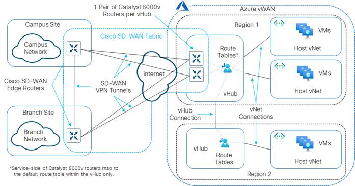
As of software release 17.6.1 / 20.6.1, only two Cisco Catalyst 8000v SD-WAN routers are provisioned by Cloud onRamp for Multi-Cloud within a vHub. The pair of Cisco Catalyst 8000v routers is instantiated within the vHub for resiliency. Throughput capacity of the SD-WAN connectivity is based upon the underlying Azure virtual machines (VMs) chosen to run the Catalyst 8000v router instances. Additional SD-WAN routers cannot be provisioned within the vHub via Cloud onRamp for Multi-Cloud if additional capacity is required.
As of software release 17.6.1 / 20.6.1 only a single Cloud Gateway – and more specifically a single pair of Catalyst 8000v routers – can be instantiated within a given Azure region. However, each Azure region may have its own vHub. You can create a Cloud Gateway in each Azure region within the vWAN to scale the throughput capacity across the deployment.
Only two physical interfaces are created on each of the Cisco Catalyst 8000v SD-WAN routers when they are instantiated within the Azure vHub. The first physical interface (GigabitEthernet1) of each of the Catalyst 8000v routers is configured as an WAN transport (VPN 0) interface and attached to a subnet within the vHub. IP addresses are dynamically assigned from the subnet address space. Internet connectivity is provided through Azure public IP addresses, also assigned to the WAN interfaces. Hence, the WAN interfaces use the Internet for the SD-WAN fabric underlay connectivity. The SD-WAN fabric overlay is created via IPsec tunnels which use the Internet as the underlay.
| Technical Note |
| As of software release 17.6.1 / 20.6.1, Cisco Cloud onRamp for Multi-Cloud does not automate any integration with Azure ExpressRoute as part of the SD-WAN underlay. However, Azure ExpressRoute circuits can be accommodated as part of the SD-WAN underlay through manual provisioning. This will be discussed the Alternative Azure Designs section. |
The second physical interface (GigabitEthernet2) of each of the Catalyst 8000v routers is configured as an SD-WAN service (LAN) interface and attached to a different subnet within the vHub. The LAN interfaces are dynamically assigned private IP addresses within the subnet IP address space within the Azure vHub. No Azure public IP addresses are assigned to the LAN interfaces.
The service VPN to which the LAN interfaces belongs, is dynamically configured when the first host vNet is mapped to the vHub within the Intent Management section of the Cloud onRamp for Multi-Cloud provisioning workflow. Since there is only a single LAN interface, and since Azure does not support sub-interfaces, only a single SD-WAN service VPN can be extended to Azure with Cisco Cloud onRamp for Multi-Cloud currently.
External BGP (eBGP) peering is established between the service-side physical LAN interfaces (GigabitEthernet2) of the Cisco Catalyst 8000v SD-WAN routers and the internal router/route server with the Azure vHub. The eBGP peering is dynamically configured on the Catalyst 8000v SD-WAN routers when the first host vNet is mapped to the vHub within the Intent Management section of the Cloud onRamp for Multi-Cloud provisioning workflow. Routes exchanged via the eBGP peering of the SD-WAN routers and the Azure vHub router/route server are mapped to the default route table of the vHub. Because only the default route table is used for the eBGP peering, the Cloud onRamp for Multi-Cloud workflow that automates the mapping of host vNets to the vHub also maps host vNets only to the default route table of the vHub. In other words, only the default route table of the vHub is used with the automation of Cisco Cloud onRamp for Multi-Cloud.
The Cisco Cloud onRamp for Multi-Cloud automation also configures propagation of routes between the host vNets such that the host vNets can communicate with each other. Within the Catalyst 8000v routers instantiated as NVAs within the vHub, BGP routes are redistributed into the Overlay Management Protocol (OMP) and vice-versa. This allows the host vNets to communicate with the rest of the SD-WAN fabric overlay – for the service VPN mapped within the Intent Management section of the Cloud onRamp for Multi-Cloud automation workflow.
Deploy - Cisco Cloud onRamp for Multi-Cloud with Azure
Cisco Cloud onRamp for Multi-Cloud with Azure uses APIs to automate the following:
● Deployment of a vWAN within your Azure subscription if you have not already deployed an Azure vWAN. Cisco Cloud onRamp for Multi-Cloud can also use an existing vWAN if you have already deployed one within your subscription.
● Deployment of a vHub within the Azure region that you specify within the vManage workflow during deployment. Since the vHub resource is managed by Azure, all you need to specify is an IP address range. Azure creates all the necessary subnets, route tables, security groups, etc. as necessary for the vHub. Cisco Cloud onRamp for Multi-Cloud can also use an existing vHub If you have already deployed one within the Azure region.
| Technical Note |
| The minimum IP address CIDR block supported for a vHub is specified by Azure as /24. |
● Deployment of a single pair of Catalyst 8000v SD-WAN routers functioning as Network Virtual Appliances (NVAs) within the vHub. Each of the Cisco Catalyst 8000v routers within the pair is instantiated within a different Azure availability zone for resiliency. The combination of the Catalyst 8000v routers and the vHub are referred to as the Cloud Gateway.
● Connectivity of the Catalyst 8000v routers to the rest of the Cisco SD-WAN fabric through IPsec VPN tunnels established over the Internet (using Azure public IP addresses) as the transport (VPN 0) interface.
| Technical Note |
| As of software release 17.6.1 / 20.6.1, Cisco Cloud onRamp for Multi-Cloud does not automate any integration with Azure ExpressRoute as part of the SD-WAN underlay. However, Azure ExpressRoute circuits can be accommodated as part of the SD-WAN underlay through manual provisioning. This is discussed in the Alternative Azure Designs section of this document. |
● Discovery and tagging of host vNets within your Azure subscription or within other Azure subscriptions. Tagging is used to facilitate the delivery of intent – which refers to the automated mapping of host vNets to the vHub.
● Delivery of intent within the vManage workflow during the deployment. Intent includes the following:
◦ Mapping of one or more tagged host vNets to the vHub through Azure vNet connections. Host vNets are mapped to the default route table of the vHub.
◦ Dynamic configuration of the selected service VPN onto the service-side interface of the pair of Cisco Catalyst 8000v SD-WAN routers functioning as NVAs within the Azure vHub.
◦ Provisioning of external BGP (eBGP) peering between the pair of Cisco Catalyst 8000v SD-WAN routers functioning as NVAs within the Azure vHub and the internal router/route server within the Azure vHub. eBGP peering is done through the service-side interface of the pair of Cisco Catalyst 8000v SD-WAN routers.
◦ Mapping of host vNet IP address spaces and IP addresses learned via eBGP peering, to the default route table of the vHub.
| Technical Note |
| Azure uses BGP autonomous system number (ASN) 65515 by default for the vHub. You must select a different BGP ASN for the Cisco Catalyst 8000v SD-WAN routers functioning as NVAs within the vHub to accomplish external BGP (eBGP) peering. |
The delivery of intent completes the configuration which provides the connectivity from the Cisco SD-WAN fabric to one or more Azure host vNets through the service VPN configured on the Cisco Catalyst 8000v SD-WAN routers within the vHub. All host vNets are mapped to a single service VPN on the Cisco Catalyst 8000v SD-WAN routers within the Azure vHub. If traffic separation is desired, depending upon your requirements it may be possible to accomplish through centralized policy allowing and/or preventing connectivity between prefixes. Centralized policy is outside the scope of this guide and will not be covered here.
Host vNets can be automatically mapped to the vHub by Cisco Cloud onRamp for Multi-Cloud within the workflow either during the creation of the Cloud Gateway or added after the Cloud Gateway has been created. For the use case in this deployment guide, the host vNets are mapped to the vHub after the Cloud Gateway has been created.
Before configuring Cisco Cloud onRamp for Multi-Cloud with Azure, the following prerequisites must be met:
● Verify you meet the Azure prerequisites
● Verify you have available software tokens / licenses for two Cisco Catalyst 8000v routers in Cisco vManage
● Configure feature and device templates for the Cisco Catalyst 8000v routers that will be used within the Cloud Gateway
● Deploy the device template to the software tokens representing the Cisco Catalyst 8000v routers that will be used within the Cloud Gateway
The following procedures assist with validating and configuring the prerequisites for Cisco Cloud onRamp for Multi-Cloud with Azure. If you already meet the prerequisites, you can skip this section and move on to the Deploy a Cloud Gateway with Cisco Cloud onRamp for Multi-Cloud section.
Procedure 1. Verify the Azure Prerequisites
The Azure prerequisites for deploying a Cloud Gateway with Cisco Cloud onRamp for Multi-Cloud are discussed in detail within Appendix E. At a high level, the requirements are summarized as follows:
● You must have a subscription within Azure marketplace to utilize Cisco Catalyst 8000v router images.
● You must ensure that your Azure subscription has the privileges to create the necessary resources within Azure.
● Your vManage must have Internet connectivity and the necessary firewall ports open for REST-based API calls between Cisco Cloud onRamp for Multi-Cloud and Azure.
Please refer to Appendix E for additional details on these requirements as necessary.
Procedure 2. Verify You Have at Least Two Unused Cisco Catalyst 8000v Routers within Cisco vManage
Cisco Cloud onRamp for Multi-Cloud with Azure supports the instantiation of Cisco Catalyst 8000v SD-WAN routers functioning as NVAs within the Azure vHub. Cisco CSR 1000v and vEdge Cloud routers are not supported with the Cisco Cloud onRamp for Multi-Cloud workflow with Azure.
The following are the steps for this procedure.
Step 1. Log into the Cisco vManage web console using the IP address or fully qualified domain name of your Cisco vManage instance.
For example: https://<Cisco_vManage_ipaddr_or_FQDN>:8443/
Step 2. In the navigation panel on the left side of the screen, select Configuration > Devices.
This will bring up the Devices screen. An example is shown in the figure below.
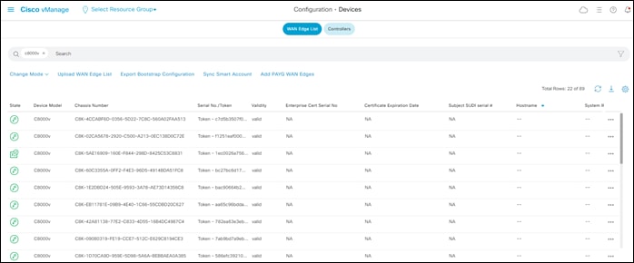
Step 3. Verify that you have at least two valid Cisco Catalyst 8000v routers that are not being used already. Valid unused devices should have the word “valid” under the Validity column. The Assigned Template, Device Status, Hostname, System IP, and Site ID columns should be blank.
Cisco Catalyst 8000v routers are sold as a software subscription license. Go to software.cisco.com and use the Plug and Play Connect portal to add tokens / licenses and sync or upload them to vManage if you have insufficient Cisco SD-WAN Edge software router tokens.
Procedure 3. Configure Feature & Device Templates for the Catalyst 8000v Routers used as NVAs within the Azure vHub
You must have at least a minimal device template assigned within Cisco vManage to the software tokens that represent the Cisco Catalyst 8000v routers that Cisco Cloud onRamp for Multi-Cloud provisions within the Azure vHub.
Cisco provides a minimum default device template named Default_Azure_vWAN_C8000V_Template_V01 to help you get started. This default device template consists of multiple default feature templates. If you choose, you can deploy the Cloud Gateway using these default device and feature templates.
It should be noted that you cannot modify a default template. However, you can change any values of device variables within the default templates that were manually entered while instantiating the SD-WAN routers, and then re-deploy the changes to the running SD-WAN routers. If you wish to change the template itself, you must first copy the template. Once you have a copy of the default template, you can then modify the copy of the template.
| Technical Note |
| When deploying a Cloud Gateway within Azure using vManage release 20.7 with Catalyst 8Kv routers running software release 17.6, the default device template (Default_Azure_vWAN_C8000V_Template_V01) may result in Catalyst 8000v routers not establishing control plane connections with vManage. It is recommended that you try the following: delete the Cloud Gateway within vManage, copy the default device template (Default_Azure_vWAN_C8000V_Template_V01), edit the new template to remove the second Cisco VPN Interface Ethernet feature template (Default_Azure_vWAN_C8000V_VPN0_INTF_GE2_V01) from the transport VPN (VPN 0), and then re-deploy the Cloud Gateway using the new template with only one WAN transport interface. |
After you have implemented the Default_Azure_vWAN_C8000V_Template_V01 template within the Cloud Gateway, you can modify the configuration of the Catalyst 8000v SD-WAN routers within the Cloud Gateway by making copies of the device and feature templates, swapping out the necessary default templates with the copies as needed, and re-deploying to the running Catalyst 8000v SD-WAN routers within the Cloud Gateway. At a minimum it is recommended to modify the userid / password within the Cisco AAA template, in order to secure access to the Cisco Catalyst 8000v routers within the Cloud Gateway.
This deployment guide follows the strategy of deploying device and feature templates with a more complete configuration when the Cloud Gateway is instantiated. This template strategy is simply the choice of the author of this guide, based upon the concept that cloud infrastructure should be immutable as much as possible. The device template, saville-C8Kv-Azure-vHub, used for the Catalyst 8000v SD-WAN routers, as well as the various feature templates which make up the device template, are discussed in Appendix C.
| Technical Note |
| Please refer to the Cisco SD-WAN Deployment Guide located at the following URL, for step-by-step instructions as to how to create individual feature templates and device templates within Cisco vManage if necessary. https://www.cisco.com/c/dam/en/us/td/docs/solutions/CVD/SDWAN/SD-WAN-End-to-End-Deployment-Guide.pdf |
Procedure 4. Attach Device Templates to the Software Tokens Representing the Cisco Catalyst 8000v Routers used in the Azure Cloud Gateway
When you attach a device template to Cisco Catalyst 8000v routers, Cisco vManage builds the configurations based on the feature templates and then associates the configuration with the software tokens representing the Cisco Catalyst 8000v routers that will be used within the Cloud Gateway. For Cisco Catalyst 8000v routers, the configuration, along with a One-Time Password (OTP) – unique to each device, are included within the cloud-init file. The OTP is used by the Cisco Catalyst 8000v router to initially authenticate to the Cisco vBond and vManage controllers. The cloud-init files are automatically uploaded to Azure as Custom Data within the Cloud onRamp for Multi-Cloud automation when the Cisco Catalyst 8000v routers are instantiated.
However, before the configuration can be built and pushed out, you need to first define all variables within the feature templates attached to the device template. There are two ways to do this, either by entering in the values of the variables manually within the GUI, or by uploading a .csv file with a list of the variables and their values. Both methods are discussed within the Cisco SD-WAN Deployment Guide referenced earlier. This section of the deployment guide will only discuss entering values manually.
The following are the steps:
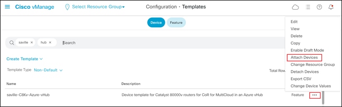
Step 1. Go to Configuration > Templates and select the Device tab.
Step 2. Find the desired device template.
The example within this section will highlight the steps for deploying the device template named saville-C8Kv-Azure-vHub to Cisco Catalyst 8000v routers.
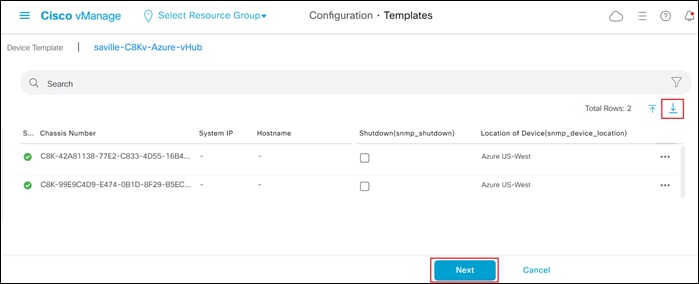
Step 3. Select the … to the right of the template, and from the drop-down menu select Attach Devices.
An example is shown in the following figure.
A pop-up window listing the available devices to be attached to this configuration will appear. The list of available devices will contain either the hostname and IP address of a device, if it is known through Cisco vManage; or the chassis serial number of a device, if it has not yet come up on the network and is unknown by Cisco vManage. Cisco Catalyst 8000v routers are assigned a chassis serial number although there is no physical chassis. The list contains only the device model that was defined when the template was created (for this deployment guide, Cisco Catalyst 8000v routers).
Step 4. Select the devices to which you wish to apply the configuration template and select the arrow to move the device from the Available Devices box to the Selected Devices box.
You can select multiple devices at one time by simply clicking each desired device.
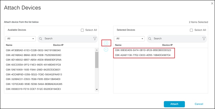
Step 5. Click the Attach button.
A new screen will appear, listing the devices that you have selected. An example is shown in the following figure.
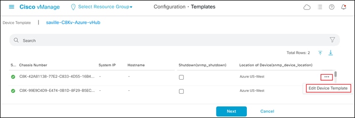
Step 6. Find the first Cisco SD-WAN Edge device, select … to the far right of it, and from the drop-down menu select Edit Device Template.
A pop-up screen will appear with a list of variables and empty text boxes. There may also be variables with check boxes to check/uncheck for on/off values. An example is shown in the figure below.
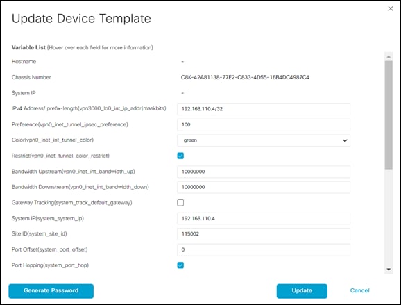
Step 7. Fill in the values of the variables in the text boxes.
All text fields must be filled in. If you leave a text field empty, the box around the text field will be highlighted red when you try to move to the next page. Check boxes can be left unchecked. For check boxes, checked means “Yes” and unchecked means “No”.
The following tables show the variables used when deploying the pair of Cisco Catalyst 8000v routers for this deployment guide.
Table 1. AzureC8Kv1 Device Template Variable Values
| Variable |
Value |
| IPv4 Address/ prefix-length(vpn3001_lo0_int_ip_addr|maskbits) |
192.168.110.4/32 |
| Preference (vpn0_inet_tunnel_ipsec_preference) |
100 |
| Color(vpn0_inet_int_tunnel_color) |
green |
| Restrict(vpn0_inet_tunnel_color_restrict) |
✓ |
| QoS Map(qos_map) |
4Q_QoS_Map |
| Bandwidth Upstream (vpn0_inet_int_bandwidth_up) |
10000000 |
| Bandwidth Downstream (vpn0_inet_int_bandwidth_down) |
10000000 |
| Gateway Tracking(system_track_default_gateway) |
□ |
| System IP (system_system_ip) |
192.168.110.4 |
| Site ID (system_site_id) |
115002 |
| Port Offset (system_port_offset) |
0 |
| Port Hopping (system_port_hop) |
✓ |
| Hostname (system_host_name) |
AzureC8Kv1 |
| Longitude(system_longitude) |
-121.9552 |
| Latitude (system_latitude) |
37.3541 |
| Device Groups(system_device_groups) |
saville_Azure |
| Console Baud Rate (bps)(system_console_baud_rate) |
19200 |
| VPN_ID (snmp_trap_vpn_id) |
3001 |
| Source Interface(snmp_trap_source_interface) |
Loopback0 |
| IP Address(snmp_trap_ip) |
192.168.101.102 |
| Shutdown (snmp_shutdown) |
□ |
| Location of Device(snmp_device_location) |
Azure US-West |
| Source Interface(https_client_source_interface) |
GigabitEthernet1 |
| Hello Interval (milliseconds) (bfd_color_hello_interval) |
1000 |
| Color(bfd_color) |
Green |
| Poll Interval (milliseconds)(bfd_poll_interval) |
600000 |
| Hostname/IP Address(vpn0_ntp_server_host) |
time.nist.gov |
| VPN ID (logging_server_vpn) |
3001 |
| Hostname/IPv4 Address(logging_server_ip_addr) |
192.168.101.102 |
Table 2. AzureC8Kv2 Device Template Variable Values
| Variable |
Value |
| IPv4 Address/ prefix-length(vpn3001_lo0_int_ip_addr|maskbits) |
192.168.110.5/32 |
| Preference (vpn0_inet_tunnel_ipsec_preference) |
100 |
| Color(vpn0_inet_int_tunnel_color) |
green |
| Restrict(vpn0_inet_tunnel_color_restrict) |
✓ |
| QoS Map(qos_map) |
4Q_QoS_Map |
| Bandwidth Upstream (vpn0_inet_int_bandwidth_up) |
10000000 |
| Bandwidth Downstream (vpn0_inet_int_bandwidth_down) |
10000000 |
| Gateway Tracking(system_track_default_gateway) |
□ |
| System IP (system_system_ip) |
192.168.110.5 |
| Site ID (system_site_id) |
115002 |
| Port Offset (system_port_offset) |
0 |
| Port Hopping (system_port_hop) |
✓ |
| Hostname (system_host_name) |
AzureC8Kv2 |
| Longitude(system_longitude) |
-121.9552 |
| Latitude (system_latitude) |
37.3541 |
| Device Groups(system_device_groups) |
saville_Azure |
| Console Baud Rate (bps)(system_console_baud_rate) |
19200 |
| VPN_ID (snmp_trap_vpn_id) |
3001 |
| Source Interface(snmp_trap_source_interface) |
Loopback0 |
| IP Address(snmp_trap_ip) |
192.168.101.102 |
| Shutdown (snmp_shutdown) |
□ |
| Location of Device(snmp_device_location) |
Azure US-West |
| Source Interface(https_client_source_interface) |
GigabitEthernet1 |
| Hello Interval (milliseconds) (bfd_color_hello_interval) |
1000 |
| Color(bfd_color) |
Green |
| Poll Interval (milliseconds)(bfd_poll_interval) |
600000 |
| Hostname/IP Address(vpn0_ntp_server_host) |
time.nist.gov |
| VPN ID (logging_server_vpn) |
3001 |
| Hostname/IPv4 Address(logging_server_ip_addr) |
192.168.101.102 |
Interface names for Cisco Catalyst 8000v routers start with GigabitEthernet1. Subsequent interfaces follow the standard conventions for Cisco IOS XE devices – GigabitEthernet2, GigabitEthernet3, etc.
Step 8. When you have filled in the values of the variables in the text boxes, select Update.
This will fill in all the variables for the template for the first Cisco Catalyst 8000v router.
Step 9. Repeat Steps 6 – 8 for the other Catalyst 8000v router.
Step 10. When you are finished filling out the variables and before moving further, download the .csv file by selecting the download arrow symbol in the upper right corner.
The .csv file will be populated with the values you have filled in so far. If you deploy the configuration, and for any reason there is an error in one of the input variables, the configuration may fail to deploy. When you come back to this page, all the values will be gone, and you will need to enter them in again.
If you downloaded the populated .csv file, just upload it by selecting the up arrow. Then you can select … to the right of the desired device and select Edit Device Template, and your latest values will be populated in the text boxes. You can then modify any input values and try to deploy again.
Step 11. When you are ready to deploy, select the Next button.
The next screen will indicate that the template (or templates if you used multiple device templates) will be applied to the devices. An example is shown in the figure below.
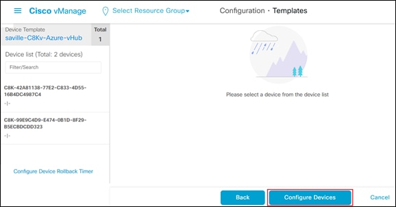
If you forget to add values for a device, you will get an error and you won't be able to move forward until that is corrected.
Selecting any device in the left-hand panel will show you the configuration that will be pushed to that Catalyst 8000v device (through the Config Preview tab).
Appendix D shows the configuration pushed to one of the Cisco Catalyst 8000v routers (AzureC8Kv1) from the configuration templates.
Step 12. Click on the Configure Devices button.
A pop-up window will appear, informing you that committing the changes will affect the configuration on the Cisco Catalyst 8000v devices, and asking you to confirm that you want to proceed.
Step 13. Check the box next to Confirm configuration changes on 2 devices and click on the OK button.
The Task View screen will then appear. After a few moments the status of the Cisco Catalyst 8000v SD-WAN Edge routers will appear as “Done – Scheduled” with a message indicating that the device is offline and that the template will be attached to the device when it comes online. An example is shown in the figure below.
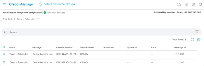
The Cisco Catalyst 8000v SD-WAN Edge routers are now ready to be deployed within the Azure Cloud Gateway by Cisco Cloud onRamp for Multi-Cloud.
Process: Deploy a Cloud Gateway with Cisco Cloud onRamp for Multi-Cloud
This section discusses the procedures for deploying an Azure Cloud Gateway using Cisco Cloud onRamp for Multi-Cloud.
Procedure 1. Login to Cisco vManage and Navigate to Cloud onRamp for Multi-Cloud
Step 1. Login to the Cisco vManage web console using the IP address or fully qualified domain name of your Cisco vManage instance.
For example: https://Cisco_vManage_ip_addr_or_FQDN:8443/
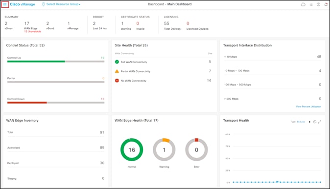
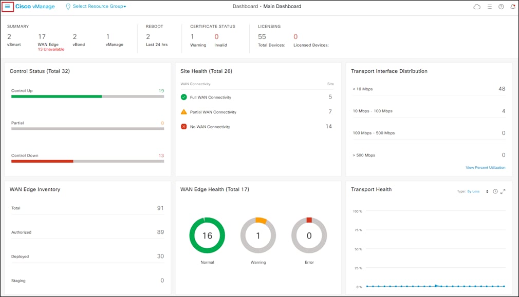
This will bring up the Cisco vManage dashboard, as shown in the following figure.
Step 2. Click the three bars in the upper left corner of the screen to bring up a navigation panel on the left side of the screen.
Step 3. In the navigation panel, select Configuration > Cloud onRamp for Multi-Cloud.
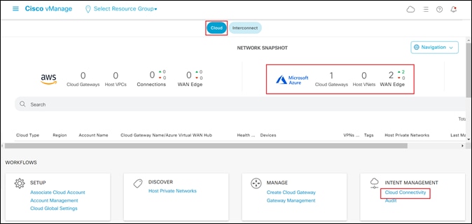
This will bring you to the initial Cisco Cloud onRamp for Multi-Cloud screen, as shown in the figure below.
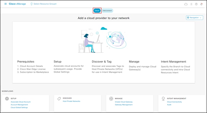
Step 4. Make sure the Cloud button at the top of the screen is selected, as shown in the figure above.
Cloud onRamp for Multi-Cloud has four main workflows: Setup, Discover, Manage, and Intent Management - each with one or more actions that need to be performed. This guide will walk you through each of the actions within each of the workflows as a separate procedure.
Procedure 2. Setup – Associate Cloud Account
The Setup workflow allows you to do the following:
● Add new cloud accounts to Cisco Cloud onRamp for Multi-Cloud
● Manage (including delete) existing cloud accounts
● Configure global settings for the Catalyst 8000v routers instantiated within the Azure vHub.
Cloud accounts include the credentials necessary to access the public IaaS cloud provider (Azure for this deployment guide) through API calls. This procedure will discuss how to add (associate) a new cloud account to Cisco Cloud onRamp for Multi-Cloud.
Step 1. To add a new cloud instance, within Setup click on Associate Cloud Account.
The Provide Cloud Account Details screen will appear.
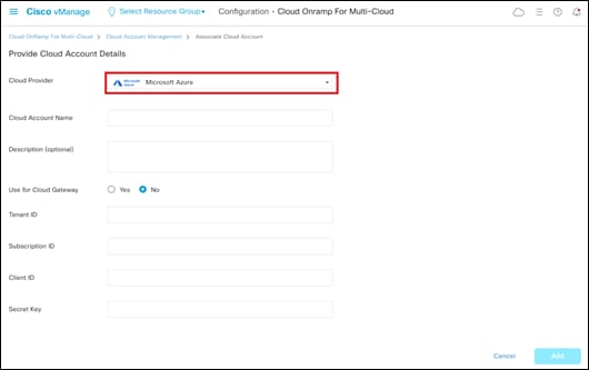
Step 2. From the drop-down menu adjacent to Cloud Provider, select Microsoft Azure.
The fields within the screen will change to reflect the credentials necessary for Cisco Cloud onRamp for Multi-Cloud to access Microsoft Azure. An example is shown in the following figure.
Step 3. Fill out the required information within the Provide Cloud Account Details screen and click the Add button.
The following table provides a brief description of each of the fields.
Table 3. Provide Cloud Account Details Screen Field Descriptions
| Field |
Description |
| Cloud Provider |
Drop-down menu containing the IaaS public cloud providers supported by Cisco Cloud onRamp for Multi-Cloud. As of vManage release 20.6.1 Amazon Web Services, Microsoft Azure, and Google Cloud Platform are supported. |
| Cloud Account Name |
Text field used to identify the cloud account within Cisco Cloud onRamp for Multi-Cloud. |
| Description (optional) |
Optional text field used for a description of the cloud account. |
| Use for Cloud Gateway |
Yes / No radio button to determine if the cloud account can be used to instantiate a Cloud Gateway within Azure. A Cloud Gateway consists of a pair of Catalyst 8000v routers instantiated within an Azure vHub. If set to No, the cloud account can still be used to map existing host vNets associated with the cloud account to a Cloud Gateway but cannot be used to instantiate a Cloud Gateway. |
| Tenant ID |
Universally Unique Identifier (UUID) / Globally Unique Identifier (GUID) representing the representing the Azure Active Directory (AD) tenant for the cloud account. Also called a Directory ID. |
| Subscription ID |
UUID / GUID identifying the subscription within this tenant. |
| Client ID |
The ID provided by Azure Active Directory (AD) when you registered your client application. Also called an Application ID. |
| Secret Key |
The client secret used by the application / service principal to prove its identity when requesting a token. |
For this deployment guide the cloud account is used to instantiate Cloud Gateways. Make sure the Use for Cloud Gateway radio button is set to Yes.
Once you have added the cloud account it should appear like the following figure.
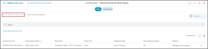
Step 4. Click on the Cloud OnRamp for Multi-Cloud link in the upper right side to the screen (as shown in the figure above) to return to the initial Cloud OnRamp for Multi-Cloud screen.
Procedure 3. Setup – Cloud Global Settings
This procedure will discuss how to configure global settings for the Cloud Gateways (Catalyst 8000v routers instantiated within the Azure vHub) within Cisco Cloud onRamp for Multi-Cloud. Global settings must be configured before you can create a Cloud Gateway. However, you can override many of the global settings when you instantiate a Cloud Gateway.
Step 1. From the initial Cisco Cloud onRamp for Multi-Cloud screen (as shown in Figure 13 above), within Setup click on Cloud Global Settings.
Step 2. Make sure the Cloud Global Settings button at the top of the screen is selected.
The Cloud Global Settings screen will appear.
Step 3. From the drop-down menu adjacent to Cloud Provider, select Microsoft Azure.
The fields within the Cloud Global Settings screen will change to reflect the credentials necessary for Cisco Cloud onRamp for Multi-Cloud to access Microsoft Azure. An example is shown in the following figure.
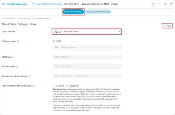
Step 4. Click on the + Add link in the upper right corner of the screen to move from View mode to Create mode. This will allow you to edit the fields.
Step 5. Fill out the required information within the Cloud Global Settings screen.
The following table provides a brief description of each of the fields as well as the values used within this deployment guide.
Table 4. Cloud Global Settings Screen Field Descriptions and Values Used in This Guide
| Field |
Description |
Values Used in This Deployment Guide |
| Cloud Provider |
Drop-down menu containing one of the three IaaS public cloud providers supported by Cisco Cloud onRamp for Multi-Cloud. As of vManage release 20.6.1 – Amazon Web Services, Microsoft Azure, and Google Cloud Platform are supported. |
Microsoft Azure |
| Software Image |
Cisco SD-WAN software image which will run on the Catalyst 8000v routers functioning as Network Virtual Appliances (NVAs) within an Azure virtual hub (vHub). |
17.4.20201218 |
| SKU Scale |
The SKU scale determines the throughput per instance for the Catalyst 8000v SD-WAN routers which are instantiated within the vHub. Each SKU represents approximately 0.5 Gbps of throughput. Hence a SKU of 2 represents approximately 1 Gbps, a SKU of 4 represents approximately 2 Gbps, and a SKU of 10 represents approximately 5 Gbps of performance. |
4 |
| IP Subnet Pool |
Specifies the IP address range to be used when Microsoft Azure creates a vHub. The IPv4 CIDR block range must be between /16 and /24. Azure controls the partitioning of this IP address space for the various subnets created within the vHub. |
192.168.112.0/23 |
| Autonomous System Number |
The BGP autonomous system number of the Catalyst 8000v routers functioning as NVAs within the Azure vHub. The Catalyst 8000v routers form eBGP peering with the Azure vHub. |
65010 |
| Push Monitoring Metrics to Azure |
Radio button which enables / disables sharing of telemetry data with Microsoft. |
Disabled |
Step 6. When you have finished filling out the fields within the Cloud Global Settings screen click the Save button which appears at the bottom of the screen when you click the + Add link.
This will bring up a screen indicating you have successfully added global account settings for Microsoft Azure.
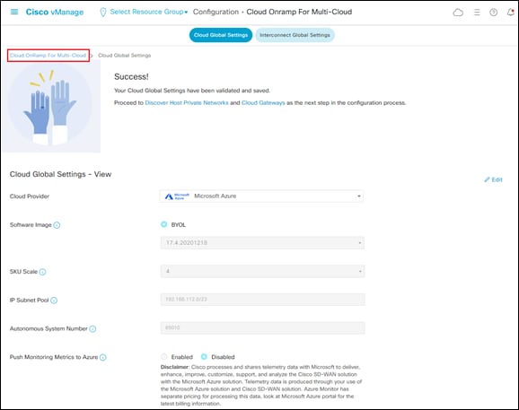
Step 7. Click on the Cloud OnRamp for Multi-Cloud link in the upper right side to the screen, as shown in the figure above, to return to the initial Cloud OnRamp for Multi-Cloud screen.
Procedure 4. Discover – Host Private Networks
This procedure can be done either before or after you create a Cloud Gateway. However, in keeping with the steps in the Cloud onRamp for Multi-Cloud workflow, it will be discussed here. You must have at least one existing host vNet in order to complete this procedure.
Within Cisco Cloud onRamp for Multi-Cloud, existing host vNets must first be discovered and tagged before they can be mapped to a Cloud Gateway. Tagging host vNets provides a flexible abstraction, making it visually easier to map one or more host vNets to a service VPN within the SD-WAN overlay.
The mapping of host vNets to a Cloud Gateway provides network connectivity from the SD-WAN overlay to the host vNets. Mapping is done within the Intent Management workflow (discussed in an upcoming procedure).
Step 1. From the initial Cisco Cloud onRamp for Multi-Cloud screen (shown in Figure 13), within Discover click on Host Private Networks.
This will bring up the Discover Host Private Networks screen.
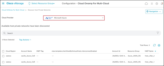
Step 2. From the drop-down menu adjacent to Cloud Provider, select Microsoft Azure.
This will cause Cisco Cloud onRamp for Multi-Cloud to discover and display all untagged host vNets associated with any of the Microsoft Azure cloud accounts added to Cloud onRamp for Multi-Cloud.
An example is shown in the following figure.
Step 3. Select one or more host vNets which you wish to tag, and from the Tag Actions drop-down menu, select Add Tag, as shown below.
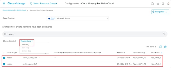
This will bring up the Add New Tag screen.
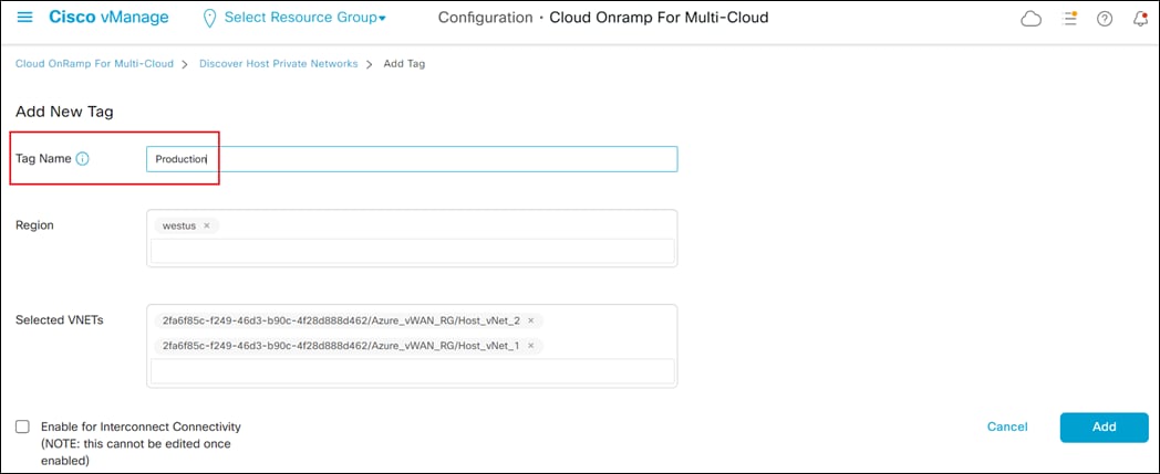
You can choose to use tags in various ways. For example, you can choose to tag multiple host vNets associated with a particular business function within your organization with a tag name indicating the business function – such as Production, Development, Test, etc. That allows you to map multiple host vNets all with the same business function to the Cloud Gateway at one time. Alternatively, you can simply choose to tag each host vNet with a tag name indicating the name of the host vNet. That allows you to individually select the host vNets you wish to map to the Cloud Gateway.
Step 4. In the open text field adjacent to Tag Name, type in the name of the tag which you wish to assign to the host vNet(s).
This design guide follows the model where both host vNets (Host_vNet_1 and Host_vNet_2) are assigned the business function tag name of Production, indicating the workloads within those vNets are production workloads.
The Region and Selected VNETs fields should be automatically filled. The Enable for Interconnect Connectivity should be checked if you are using the host vNet for Cisco SD-WAN interconnect connectivity (Megaport and/or Equinix). This is not covered within this deployment guide and left unchecked.
| Technical Note |
| It should be noted that regardless of whether you assign host vNets individual tag names, or aggregate multiple host vNets with tag names indicating business function, you can only map host vNets to a single service VPN within the SD-WAN network, as of vManage release 20.6.1. The Catalyst 8000v routers functioning as NVAs within the Azure vHub support only one service-side interface (GigabitEthernet2). This service-side interface must be assigned to a single service VPN. eBGP peering is established from the service-side interface of each of the Catalyst 8000v SD-WAN routers to the internal router/route server within the vHub. Routes learned via the eBGP peering are automatically mapped to the default route table of the Azure vHub. Hence, for connectivity, all host vNets mapped to the Cloud Gateway are also assigned to the default route table of the Azure vHub. |
Step 5. Click the Add button to tag the host vNets.
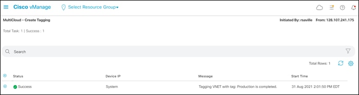
After a few moments Cisco Cloud onRamp for Multi-Cloud will display a screen indicating that the host vNets have been successfully tagged.

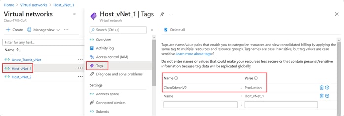
From a Microsoft Azure perspective, Cisco Cloud onRamp for Multi-Cloud uses API calls to add the following tag to the Host_vNet_1 and Host_vNet_2 vNets:
Name: CiscoSdwanV2
Value: Production
This can be seen within the Microsoft Azure portal for the individual host vNets as well.
This completes the discovery and tagging of the host vNets. In the next procedure, the Cloud Gateway will be instantiated within the Azure vHub.
Procedure 5. Manage – Create Cloud Gateway
Step 1. From the initial Cisco Cloud onRamp for Multi-Cloud screen within Manage (shown in Figure 13), click on Create Cloud Gateway.
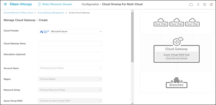
This will bring up the Manage Cloud Gateway - Create screen.
Step 2. From the drop-down menu adjacent to Cloud Provider, select Microsoft Azure.
This will cause the screen to change to reflect the fields necessary to instantiate a Cloud Gateway within Azure. An example is shown in the following figure.
Step 3. Fill in the required fields.
The following table provides a brief description of each of the fields as well as the values used within this deployment guide.
Table 5. Managed Cloud Gateway - Create Screen Field Descriptions and Values Used in This Guide
| Field |
Description |
Values Used in This Deployment Guide |
| Cloud Provider |
Drop-down menu containing one of the three IaaS public cloud providers supported by Cisco Cloud onRamp for Multi-Cloud. As of vManage release 20.6.1 – Amazon Web Services, Microsoft Azure, and Google Cloud Platform are supported. |
Microsoft Azure |
| Cloud Gateway Name |
End user specified name for the Cloud Gateway instantiated within Azure. |
AzureCGW |
| Description (Optional) |
Optional end user specified description for the Cloud Gateway instantiated within Azure. |
None |
| Account Name |
Drop-down menu containing the list of cloud accounts that have been added to Cloud onRamp for Multi-Cloud and allowed to create a Cloud Gateway. Select the cloud account under which the Cloud Gateway will be instantiated. |
Saville_CoR_Azure |
| Region |
Drop-down menu containing the list of Azure regions. Select the region in which you wish to instantiate the Cloud Gateway. |
westus |
| Resource Group |
Drop-down menu containing the list of existing Azure resource groups within the cloud account specified within the Account Name drop-down menu above. Select the resource group within the cloud account in which you wish to instantiate the Cloud Gateway or select Create New… to create a new Azure resource group within the Azure subscription to which the cloud account belongs. |
Azure_vWAN_RG |
| Azure Virtual WAN |
Drop-down menu containing the list of existing Azure vWANs within the cloud account specified within the Account Name drop-down menu above. Select the vWAN within the cloud account in which you wish to instantiate the Cloud Gateway or select Create New… to create a new vWAN within the Azure subscription to which the cloud account belongs. Note: If you do not see existing vWANs in your cloud account within the drop-down menu, check to ensure that your Azure credentials have not expired. |
Create New… -> Azure_vWAN |
| Azure Virtual WAN Hub |
Drop-down menu containing the list of existing Azure vHubs in the vWAN specified within the Azure Virtual WAN drop-down menu above. If you selected Create New… to create a new vWAN, this field will be automatically filled in for you with the following entry: Create New VHUB using Cloud Gateway Name. This indicates that a new vHub will be created using the same name as the Cloud Gateway specified within the Cloud Gateway Name field above. Note: If you do not see existing vHubs in your cloud account within the drop-down menu, check to ensure that your Azure credentials have not expired. |
Create New VHUB using Cloud Gateway Name |
| Settings -> Software Image |
Drop-down menu listing the Cisco SD-WAN software images available to run on the Catalyst 8000v routers functioning as NVAs within the Azure vHub. Select the image you wish to run on the Catalyst 8000v routers. BYOL – meaning bring your own license is the only option for licensing. This field is copied from the Cloud Global Settings discussed previously. However, it can be overridden during instantiation of a Cloud Gateway. Note: If you do not see any available software images within the drop-down menu, check to ensure that your Azure credentials have not expired. |
17.6.01 |
| Settings -> SKU Scale |
Drop-down menu listing the available SKU scales for Catalyst 8000v routers functioning as NVAs within the vHub. Select the SKU scale for the Catalyst 8000v routers you will be instantiating within the Cloud Gateway. The SKU scale determines the throughput per instance for the Catalyst 8000v SD-WAN routers which are instantiated within the vHub. Each SKU represents approximately 0.5 Gbps of throughput. Hence a SKU of 2 represents approximately 1 Gbps, a SKU of 4 represents approximately 2 Gbps, and a SKU of 10 represents approximately 5 Gbps of performance. This field is copied from the Cloud Global Settings discussed previously. However, it can be overridden during instantiation of a Cloud Gateway. |
2 |
| Settings -> IP Subnet Pool |
Specifies the IP address range to be used when Microsoft Azure creates a vHub. The IPv4 CIDR block range must be between /16 and /24. Azure controls the partitioning of this IP address space for the various subnets created within the vHub. This field is copied from the Cloud Global Settings discussed previously. However, it can be overridden during instantiation of a Cloud Gateway. |
192.168.112.0/23 |
| UUID (specify 2) |
Drop-down menu which lists the Catalyst 8000v UUIDs available for instantiation within the Cloud Gateway. For a UUID to appear, it has to have already been attached to a device template which can be used to deploy the Catalyst 8000v routers functioning as NVAs within the Azure vHub. |
C8K-42A81138-77E2-C833-4D55-16B4DC4987C4 C8K-99E9C4D9-E474-0B1D-8F29-B5ECBDCDD323 |
Step 4. Once you have filled in the required fields, click Add to create the Cloud Gateway.
Creation of the Cloud Gateway can take up to 40 minutes. When the Cloud Gateway has been successfully created, the Task View screen should appear as shown in the figure below.
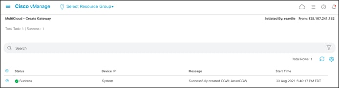
In the next process, host vNets will be mapped to the Cloud Gateway.
Process: Map Host vNets to the Cloud Gateway
This section discusses the procedures for mapping tagged host vNets to an existing Cloud Gateway. This document assumes the host vNets are already created and have been tagged within the previous process. The creation of a host vNet is outside the scope of this document.
Procedure 1. Login to Cisco vManage and Navigate to Cloud onRamp for Multi-Cloud
Step 1. Login to the Cisco vManage web console using the IP address or fully qualified domain name of your Cisco vManage instance.
For example: https://Cisco_vManage_ip_addr_or_FQDN:8443/
This will bring up the Cisco vManage dashboard, as shown in the following figure.
Step 2. Click the three bars in the upper left corner of the screen to bring up a navigation panel on the left side of the screen.
Step 3. In the navigation panel, select Configuration > Cloud onRamp for Multi-Cloud.
This will bring you to the initial Cisco Cloud onRamp for Multi-Cloud screen, as shown in the figure below.
Step 4. Make sure the Cloud button at the top of the screen is selected, as shown in the figure above.
The Cloud Gateway which you provisioned in the previous process should appear in the upper right corner of the screen. The Cloud Gateway must be provisioned before you can map host vNets to it. Review the steps within the previous process if you need to create a Cloud Gateway.
Cloud onRamp for Multi-Cloud has four main workflows: Setup, Discover, Manage, and Intent Management - each with one or more actions that need to be performed. In the previous process, we covered the Setup, Discover, and Manage workflows. The next procedure will walk you through the Cloud Connectivity action within the Intent Management workflow, which is used to map host vNets to the Cloud Gateway.
Procedure 2. Intent Management – Cloud Connectivity
Step 1. From the initial Cisco Cloud onRamp for Multi-Cloud screen (shown in the Figure 26 above), within Intent Management click on Cloud Connectivity.
This will bring up the Intent Management - Connectivity screen.
Step 2. Make sure the Mapping tab at the top of the screen is selected.
Step 3. From the drop-down menu adjacent to Cloud Provider, select Microsoft Azure.
This will cause the screen to change to reflect the current mappings of tags (which represent host vNets) to service VPNs within the SD-WAN overlay for Microsoft Azure.
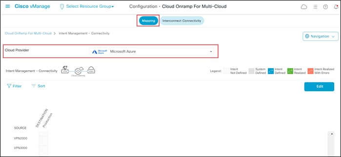
The service VPNs rows listed under the Source heading should be automatically populated, based upon the service VPNs defined within the SD-WAN overlay network. Tags which were defined during the Discover workflow (discussed in the previous process of this guide) will appear as columns under the Destination heading.
The intersection of the Source service VPN rows with the Destination tag columns creates boxes. These boxes represent the end-user intent regarding the mapping of service VPNs to host vNets. The Legend at the right side of the screen above the Edit button describes the various possibilities for intent. If no host vNets are mapped to service VPNs, all boxes will be empty, as shown in the figure above.
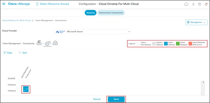
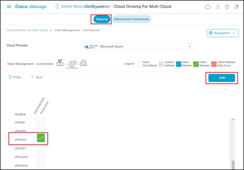
Step 4. Click the Edit button to change the intent by mapping a service VPN to one or more host vNets (represented by tags).
Step 5. Scroll down to the row which represents the service VPN that you wish to extend to Azure. You can extend only one service VPN to Azure with Cisco Cloud onRamp for Multi-Cloud with Azure.
Step 6. Within that row, move over to the column which represents the tag for the host vNet that you wish to map to the service VPN, and click on the empty box to select it.
The empty box should change to a blue color indicating Intent Defined, as shown in the Legend.
For this guide, the host vNets are mapped to service VPN 3000. An example is shown in the following figure.
You can select multiple tags to be mapped to the same service VPN – if you have multiple tags defined. However, as of software release 17.6.1 / 20.6.1, Cisco Cloud onRamp for Multi-Cloud with Azure only supports the mapping of host vNets to a single service VPN. Although you can select multiple service VPNs within the graphical user interface, DO NOT DO THIS! If you select multiple service VPNs within the intent (meaning boxes along multiple service VPN rows are highlighted in blue, indicating Intent Defined), when you try to execute that intent, nothing may be configured on the Catalyst 8000v SD-WAN routers within the Azure vHub – although the intent workflow may indicate success. Further, if you have an existing configuration on the Catalyst 8000v SD-WAN routers based upon previous intent with a single service VPN, and then you try to add a second service VPN – Cisco Cloud onRamp for Multi-Cloud may remove all intent from the routers. This can potentially result in an unscheduled loss of connectivity to Microsoft Azure and should be avoided. Always make sure that only a single service VPN is selected when configuring intent with Microsoft Azure.
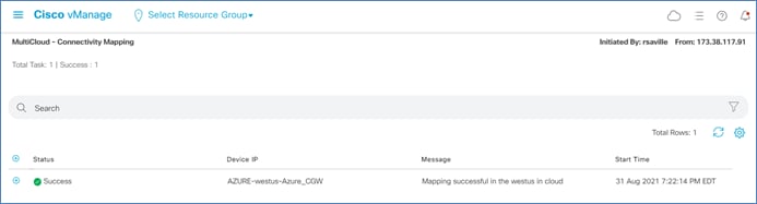
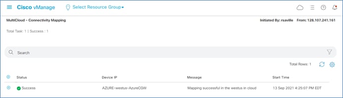
Step 7. Click the Save button to execute the intent.
After a few minutes, the MultiCloud – Connectivity Mapping screen will appear as shown in the figure below.
Intent Management: What Happens on the Catalyst 8000v SD-WAN Routers within the vHub?
When you execute the intent, Cisco Cloud onRamp for Multi-Cloud will dynamically modify the configuration of each of the Catalyst 8000v SD-WAN routers functioning as NVAs within the Azure vHub in the following ways:
● A virtual routing and forwarding (VRF) instance corresponding to the service VPN mapped to the host vNets, as specified within the Intent Management workflow, is added to each of the Catalyst 8000v routers.
● The SD-WAN service-side interface (GigabitEthernet2) of each Catalyst 8000v router is configured for dynamic IP address assignment and configured to be in the service VPN.
● BGP routing is enabled on each of the Catalyst 8000v SD-WAN routers within the Cloud Gateway. The BGP AS number configured under the Cloud Global Settings configured within the Setup workflow for Cloud onRamp for Multi-Cloud is used for both Catalyst 8000v routers.
● Each Catalyst 8000v router establishes two external BGP (eBGP) peers to the Azure vHub, using two different IP addresses which were allocated by Azure within the vHub. (Note, the eBGP peers appear under the IPv4 unicast address family for the service VPN mapped to the host vNets). The Azure vHub uses BGP AS 65515.
● BGP routes are redistributed into OMP, and OMP routes are redistributed into BGP.
● A BGP AS route map filter named AZURE_CSR_NVA_ROUTE_POLICY is applied in the outbound direction against the BGP peers in the Azure vHub. The route map does the following:
◦ Blocks routes from being sent from the last autonomous system number of the 16-bit ASN range, 65535, per IETF RFC 7300.
◦ Blocks routes from being sent that have passed through AS 65515. Since the Azure vHub uses BGP AS 65515, this essentially prevents sending routes to the vHub which have already passed through the vHub.
◦ Allows routes from any other ASNs.
● Within the service VPN, adds static routes to the two BGP peers located in the Azure vHub. The static routes point to the Azure default gateway belonging to the service side (LAN) interfaces of the Catalyst 8000v SD-WAN routers within the vHub. This ensures the BGP sessions can be established between the Catalyst 8000v SD-WAN router service-side (LAN) interfaces and the Azure vHub.
To summarize, the dynamic configuration within the Intent Management workflow extends the service VPN through the SD-WAN fabric to Azure and establishes BGP peering to dynamically exchange IP routing information for that service VPN.
Intent Management: What Happens within the Azure vHub?
When you execute the intent, Cisco Cloud onRamp for Multi-Cloud uses API calls to dynamically modify the Azure vHub to host vNet peering as follows:
● vNet peering is established from the host vNet to the vHub. On the host vNet side, the peering is configured to use the remote VNG/route server – meaning the router/route server within the vHub. This is necessary because the IP address space of the host vNet must be propagated from the vHub to the Catalyst 8000v routers through the BGP peering between the vHub and the SD-WAN routers. To propagate the routes, the vHub router/route server must be aware of the host vNet address space. Likewise, to propagate routes learned from the Catalyst 8000v routers via BGP back to the host vNet, the host vNet peering must use the remote VNG/route server.
● On the Azure vHub, the routes learned via the BGP peering with the Catalyst 8000v routers are both associated to and propagated into the Default route table. Likewise, routes from the host vNet peering connections are both associated to and propagated to the Default route table. This ensures route visibility from the service VPN of the SD-WAN fabric through to the host vNets.
To summarize, the dynamic configuration within the Intent Management workflow uses API calls to establish the vNet connections between the host vNets and the vHub; and then associates and propagates routes to the Default route table.
Operate - Cisco Cloud onRamp for Multi-Cloud
This section of the guide discusses various processes for operating the Cisco Cloud onRamp for Multi-Cloud deployment.
Process: Modifying an Existing Cloud Gateway Deployment (Optional)
This section discusses various operations which can be performed after the deployment of Cisco Cloud onRamp for Multi-Cloud with Azure. The procedures within this process are optional, and primarily included for information purposes. The following procedures are discussed:
● Adding another host vNet to an existing tag that is mapped to a service VPN
● Removing a host vNet from an existing tag that is mapped to a service VPN
● Removing the mapping of a tag to a service VPN
● Deleting a tag when the tag is not mapped a service VPN
Procedure 1. Adding Another Host vNet to a Tag that is Mapped to a Service VPN
When you add another host vNet to an existing tag that is mapped to a service VPN, the behavior is as follows:
● Cisco Cloud onRamp for Multi-Cloud uses API calls into Azure to add the tag to the host vNet
● Cisco Cloud onRamp for Multi-Cloud uses API calls to configure the host vNet-to-vHub peering of the newly tagged host vNet
Note that if the existing tag is not mapped to a service VPN, only the intent within the first bullet above (adding the tag to the host vNet) is performed.
The following are the steps for adding another host vNet to an existing tag that is mapped to a service VPN.
Step 1. From any screen within vManage, click the three bars in the upper left corner of the screen to bring up the navigation panel on the left side of the screen.
Step 2. In the navigation panel, select Configuration > Cloud onRamp for Multi-Cloud.
This will bring you to the initial Cisco Cloud onRamp for Multi-Cloud screen, as shown in the figure below.
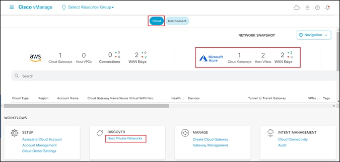
Step 3. Make sure the Cloud button at the top of the screen is selected.
You should see information regarding existing Cloud Gateways with the screen.
Step 4. Within the Discover workflow at the bottom of the screen, click on Host Private Networks.
This will bring up the Discover Host Private Networks screen.
Step 5. From the drop-down menu adjacent to Cloud Provider, select Microsoft Azure.
This will cause Cisco Cloud onRamp for Multi-Cloud to issue API calls to discover and display both tagged and untagged host vNets associated with any of the Microsoft Azure cloud accounts added to Cloud onRamp for Multi-Cloud. An example is shown in the figure below.
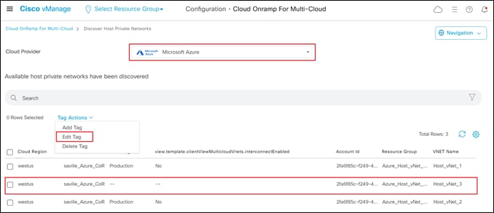
In the figure above, notice that Host_vNet_1 and Host_vNet_2 are both tagged with the Production tag, while Host_vNet_3 has no tag.
Step 6. From the drop-down menu under Tag Actions, select Edit Tag.
This will bring up the Edit Tag screen.
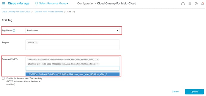
Step 7. From the drop-down menu adjacent to Tag Name, select the existing tag name to which you wish to add another host vNet.
The Selected VNETs field should automatically populate, showing you the host vNets already assigned to the tag. In the figure above you can see that once the Production tag is selected, both Host_vNet_1 and Host_vNet_2 show up as being already tagged.
Step 8. From the drop-down menu adjacent to Selected VNETs, choose the additional vNet(s) which you wish to add to the Production tag.
For this procedure, Host_vNet_3 is added to the Production tag, as shown in the figure above.
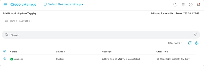
Step 9. Click the Update button to tag the additional host vNet.
After a few moments Cisco Cloud onRamp for Multi-Cloud will display a screen indicating that the host vNet(s) have been successfully tagged.
The next procedure discusses removing the tag from a host vNet when the tag is mapped to a service VPN.
Procedure 2. Removing the Tag from a Host vNet when the Tag is Mapped to a Service VPN
When a tag is applied to multiple host vNets and that tag is mapped to a service VPN, if you remove the tag from one of the host vNets the behavior is as follows:
● Cisco Cloud onRamp for Multi-Cloud uses API calls into Azure to remove the tag from the host vNet
● Cisco Cloud onRamp for Multi-Cloud uses API calls into Azure to remove the host vNet-to-vHub peering for the host vNet.
Note that if the existing tag is not mapped to a service VPN, only the intent within the first bullet above (removing the tag from the host vNet) is performed.
The steps for removing a tag that is currently mapped to a service VPN, from a host vNet, are similar to the steps for adding a host vNet to an existing tag that is currently mapped to a service VPN. The steps are as follows.
Step 1. From any screen within vManage, click the three bars in the upper left corner of the screen to bring up a navigation panel on the left side of the screen.
Step 2. In the navigation panel, select Configuration > Cloud onRamp for Multi-Cloud.
This will bring you to the initial Cisco Cloud onRamp for Multi-Cloud screen.
Step 3. Make sure the Cloud button at the top of the screen is selected.
You should see information regarding existing Cloud Gateways with the screen.
Step 4. Within the Discover workflow at the bottom of the screen, click on Host Private Networks.
This will bring up the Discover Host Private Networks screen.
Step 5. From the drop-down menu adjacent to Cloud Provider, select Microsoft Azure.
This will cause Cisco Cloud onRamp for Multi-Cloud to issue API calls to discover and display both tagged and untagged host vNets associated with any of the Microsoft Azure cloud accounts added to Cloud onRamp for Multi-Cloud.
Step 6. From the drop-down menu under Tag Actions, select Edit Tag.
This will bring up the Edit Tag screen.

Step 7. From the drop-down menu adjacent to Tag Name, select the existing tag name to which you wish to delete the host vNet.
The Selected VNETs field should automatically populate, showing you the vNets already assigned to the tag. In the figure above you can see that once the Production tag is selected, both Host_vNet_1 and Host_vNet_2 show up as being already tagged.
Step 8. Click the x to the right of one or more of the vNets already assigned to the tag within the Selected VNETs field, to delete the host vNet.
| Technical Note |
| You cannot delete the last host vNet associated with a tag through the Edit Tag under Tag Actions. Instead, you must do one of the following: ● Select Delete Tag under Tag Actions to remove the tag from Cloud onRamp for Multi-Cloud. ● Remove the mapping of the tag to the service VPN within the Intent Management Workflow. |
Step 9. Click the Update button to remove the tag from the host vNet.
After a few moments Cisco Cloud onRamp for Multi-Cloud will display a screen indicating that the host vNet has been successfully untagged.
The next procedure discusses removing the mapping of a tag to a service VPN within the Intent Management workflow.
Procedure 3. Removing the Mapping of a Tag to a Service VPN within the Intent Management Workflow.
When you remove the mapping of a tag to a service VPN within the Intent Management workflow, and the tag is the only tag mapped to the service VPN, the behavior is as follows:
● Cisco Cloud onRamp dynamically modifies the configuration of the Catalyst 8000v routers functioning as NVAs within the Cloud Gateway to remove the BGP peering with the vHub
● Cisco Cloud onRamp for Multi-Cloud uses API calls to remove the host vNet-to-vHub peerings within Azure for all of the host vNets to which the tag is applied
Note that the tag is not removed from the host vNets. This allows you to map the same tagged host vNets to a different service VPN without having to re-tag the host vNets.
The steps for removing the mapping of a tag to a service VPN within the Intent Management workflow are as follows:
Step 1. From any screen within vManage, click the three bars in the upper left corner of the screen to bring up a navigation panel on the left side of the screen.
Step 2. In the navigation panel, select Configuration > Cloud onRamp for Multi-Cloud.
This will bring you to the initial Cisco Cloud onRamp for Multi-Cloud screen.
Step 3. Make sure the Cloud button at the top of the screen is selected.
You should see information regarding existing Cloud Gateways within the screen.
Step 4. Within the Intent Management workflow at the bottom of the screen, click on Cloud Connectivity.
This will bring up the Intent Management - Connectivity screen.
Step 5. Make sure the Mapping button is selected.
Step 6. Click the Edit button to change the mapping.
Step 7. Scroll down to the green box indicating the mapping of the service VPN with the tag and click on it to de-select the mapping.
This will cause the box to become empty, indicating you have de-selected the mapping of the service VPN to the tag.
Step 8. Click the Save button at the bottom of the screen to implement your intent.
After several minutes Cisco Cloud onRamp for Multi-Cloud will display a screen indicating that the un-mapping of the service VPN to the tag has been successful.
The next procedure discusses deleting a tag from Cisco Cloud onRamp for Multi-Cloud, when the tag is not assigned to one or more host vNets which are mapped to a service VPN.
Procedure 4. Deleting a Tag when the Tag is not Assigned to One or More Host vNets Mapped to a Service VPN
You should only delete a tag within Cisco Cloud onRamp for Multi-Cloud after first removing the mapping of the tag to a service VPN within the Intent Management workflow, discussed in the previous procedure. This ensures the BGP peering between the Cisco Catalyst 8000v routers and the vHub is removed, and the host vNet-to-vHub peering within Azure is also removed – before deleting the tag. In other words, you should only delete a tag within Cisco cloud onRamp for Multi-Cloud if the tag is not currently mapped to a service VPN within the Intent Management workflow.
When a tag is applied to one or more host vNets and that tag is not mapped to a service VPN, if you delete the tag from Cisco Cloud onRamp for Multi-Cloud the behavior is as follows:
● Cisco Cloud onRamp for Multi-Cloud uses API calls to Azure to remove the tag from all host vNets to which the tag was applied
● The tag is deleted from Cisco Cloud onRamp for Multi-Cloud
The steps for deleting a tag, when the tag is assigned to one or more host vNets which are not mapped to a service VPN are as follows:
Step 1. From any screen within vManage, click the three bars in the upper left corner of the screen to bring up a navigation panel on the left side of the screen.
Step 2. In the navigation panel, select Configuration > Cloud onRamp for Multi-Cloud.
This will bring you to the initial Cisco Cloud onRamp for Multi-Cloud screen.
Step 3. Make sure the Cloud button at the top of the screen is selected.
You should see information regarding existing Cloud Gateways within the screen.
Step 4. Within the Discover workflow at the bottom of the screen, click on Host Private Networks.
This will bring up the Discover Host Private Networks screen.
Step 5. From the drop-down menu adjacent to Cloud Provider, select Microsoft Azure.
This will cause Cisco Cloud onRamp for Multi-Cloud to issue API calls to discover and display both tagged and untagged host vNets associated with any of the Microsoft Azure cloud accounts added to Cloud onRamp for Multi-Cloud.
Step 6. From the drop-down menu under Tag Actions, select Delete Tag.
This will bring up the Delete Tag screen.
Step 7. From the drop-down menu adjacent to Tag Name, select the existing tag name which you wish to delete.
The Selected VNETs field should automatically populate, showing you the vNets already assigned to the tag. In the figure above you can see that once the Production tag is selected, both Host_vNet_1 and Host_vNet_2 show up as being already tagged.
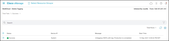
Step 8. Click the Delete button delete the tag and remove the host vNet-to-vHub peering for the host vNets associated with the tag.
Step 9. Click OK to confirm in the confirmation pop-up window that appears.
After a few moments Cisco Cloud onRamp for Multi-Cloud will display a screen indicating that the tag has been successfully deleted.
Process: Adding an Inbound Route Map to Filter BGP Routes from Azure (Optional)
As mentioned previously within this guide, Cisco Cloud onRamp for Multi-Cloud provisions a BGP AS route map filter named AZURE_CSR_NVA_ROUTE_POLICY in the outbound direction against the BGP peers in the Azure vHub. This route map filter does the following:
● Blocks routes from being sent from the last autonomous system number of the 16-bit ASN range, 65535, per IETF RFC 7300.
● Blocks routes from being sent that have passed through AS 65515. Since the Azure vHub uses BGP AS 65515, this essentially prevents sending routes to the vHub which have already passed through the vHub.
● Allows routes from any other ASNs.
Some customers may desire inbound filtering of BGP routes – either via a BGP AS route map filter or by individual prefixes, or both. This process discusses how to do that through a combination of localized route policy and CLI templates.
| WARNING |
| Cisco Cloud onRamp for Multi-Cloud dynamically modifies the BGP configuration of the Cisco Catalyst 8000v routers that function as NVAs within the Cloud Gateway – when a service VPN is mapped to a tag within the Intent Management workflow. Cisco Cloud onRamp for Multi-Cloud does not implement BGP configuration through a BGP feature template that is then applied to the service VPN within the device templates assigned to the Cisco Catalyst 8000v routers. Because of the dynamic nature of the BGP configuration with Cisco Cloud onRamp for Multi-Cloud, you must be very careful in modifying the BGP configuration through a CLI template to implement inbound filtering of BGP routes. Any mistakes in the configuration could result in a failure to add (or later remove) the BGP inbound route filter, or in some circumstances could result in the overall application of intent with the Intent Management workflow to fail. It is recommended that you first look at whether redistributing BGP routes into OMP with the Catalyst 8000v routers with the Cloud Gateway, and then implementing centralized policy to filter out unwanted routes, will meet your requirements before you consider this approach. |
Since this process discusses the use of localized route policy to filter inbound BGP routes from Azure – either using AS path lists and/or individual prefix lists you must first create a localized route policy. This is discussed in the next procedure.
Procedure 1. Create a Localized Route Policy for Filtering BGP Routes
This procedure creates a localized route policy. This localized route policy will then be included within a localized policy in the next procedure. The following are the steps to create the localized route policy.
Step 1. From any screen within vManage, click the three bars in the upper left corner of the screen to bring up a navigation panel on the left side of the screen.
Step 2. In the navigation panel, select Configuration > Policies.
This will bring you to the initial Policies screen.
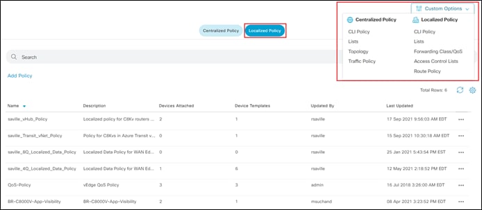
Step 3. Click on the Localized Policy button at the top center of the screen.
You should see information regarding existing localized policies defined within vManage.
The localized route policy used for this section will include both an AS path list and a prefix list. For this guide, both lists will be configured prior to creation of the route policy itself. In a real network you would normally choose to use either an AS path list filter or a prefix list filter.
AS Path List
Step 4. From the drop-down menu under Custom Options, under Localized Policy, select Lists.
Step 5. From the navigation panel on the left side of the screen select AS Path.
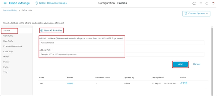
This will bring up the existing AS path lists defined within vManage.
Step 6. Click on + New AS Path List to add a new AS path list.
Step 7. In the open field under AS Path List Name type in the name of the new AS path list.
Cisco vEdge devices support alphanumeric names for AS path lists. Cisco IOS-XE devices only support numbers between 1 and 500 for AS path list names. Since Cisco Catalyst 8000v routers (which are IOS-XE devices) are instantiated within the Azure vHub using Cisco Cloud onRamp for Multi-Cloud, the name of the AS path list must be a numeric value between 1 and 500.
Step 8. In the open field under Add AS Path type in the AS path or paths, separated by commas.
The following table shows the values added for this deployment guide.
Table 6. AS Path List
| Field |
Value Used in This Deployment Guide |
| AS Path List Name |
300 |
| Add AS Path |
65515 |
For this deployment guide, BGP ASN 65515, which is used by the Azure vHub, was the only ASN included within AP Path list. This is simply for testing. Choose the values within the AS Path List as required for your deployment.
Step 9. Click Add to add the new AS Path list.
Prefix List
Step 10. From the navigation panel on the left side of the screen select Prefix.
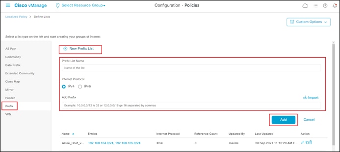
This will bring up the existing prefix lists defined within vManage.
Step 11. Click on + New Prefix List to add a new prefix list.
Step 12. In the open field under Prefix List Name type in the name of the new prefix list.
Step 13. From the radio button under Internet Protocol choose IPv4.
Step 14. In the open field under Add Prefix type in the prefix or prefixes, separated by commas.
For this deployment guide the following prefix list was created.
Table 7. Prefix List
| Field |
Value |
| Prefix List Name |
Azure_Host_vNets |
| Internet Protocol |
IPv4 |
| Add Prefix |
192.168.104.0/24,192.168.105.0/24 |
The prefix list corresponds to the IP address spaces assigned to both Azure host vNets (Host_vNet_1 and Host_vNet_2 of this guide). The prefix list defined here are simply for testing. Choose the values within the prefix list as required for your deployment.
Step 15. Click Add to add the new prefix list.
Now that the AS path and prefix lists are created, it’s time to create route policy which will include the lists.
Step 16. From the drop-down menu under Custom Options, under Localized Policy, select Route Policy.
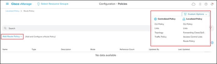
This will bring up the existing localized route policies defined within vManage.
Step 17. From the drop-down menu under Add Route Policy click Create New to add a new localized route policy.
Step 18. In the open field adjacent to Name, type in the name of the new route policy.
For this deployment guide, the name of the localized route policy is Azure_vHub_Route_Policy.
Step 19. In the open field adjacent to Description, type in a description of the new route policy.
Step 20. Click on the + Sequence Type to add a new sequence type to the route policy.
Since this is a route policy, the only choice for sequence type is Route.
Step 21. Click on the + Sequence Rule to add a new sequence rule to the route policy.
Step 22. Select the Match button to configure match actions for the rule.
Step 23. To add the AS path list to the route policy, from the menu of match rules which appear, select AS Path List.
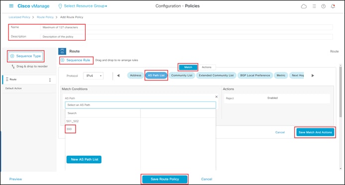
Step 24. From the drop-down menu which appears under the AS Path field, select the AS path list you configured earlier.
Step 25. Click on the Actions button to configure actions for the rule.
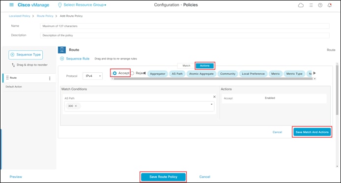
Step 26. If you want to allow the AS paths within the list, click Accept. If you want to filter out the AS paths within the list, click Reject.
Step 27. Click the Save Match and Actions button to save the sequence rule.
You can add additional sequence rules as needed to your policy.
Step 28. Click on the + Sequence Rule to add a new sequence rule to the route policy.
Step 29. To add the prefix list to the route policy, from the menu of match rules which appear, select Address.
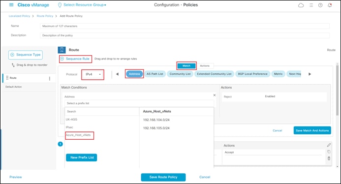
Step 30. From the drop-down menu which appears under the Address field, select the prefix list you configured earlier.
Step 31. Click on the Actions button to configure actions for rule.
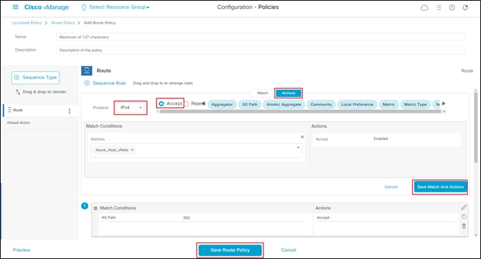
Step 32. If you want to allow the prefixes within the list, click Accept. If you want to filter out the prefixes within the list, click Reject.
Step 33. Click the Save Match and Actions button to save the sequence rule.
Note that you can change the order of the sequence rules in the route policy by dragging and dropping them in the order that you want.
Step 34. When you are done adding sequence rules, click the Save Route Policy button to save the localized route policy.
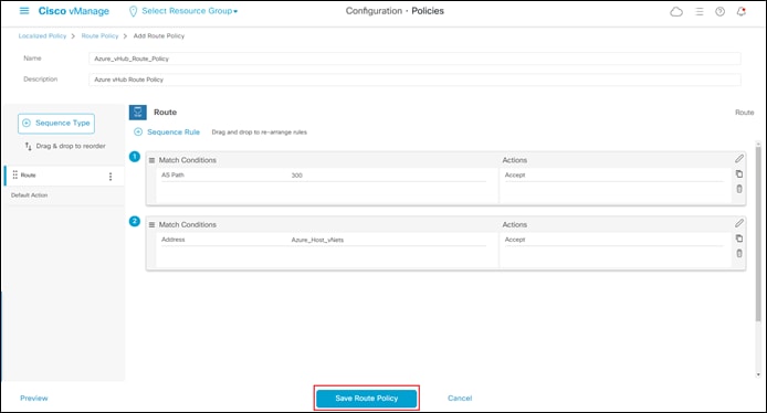
The route policy will appear as follows, after you have created it.
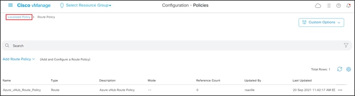
This completes the creation of the localized route policy. The localized route policy must now be included within a localized policy. This is discussed in the next procedure.
Procedure 2. Creating a Localized Policy which Includes the Localized Route Policy
Now that you have created a localized route policy, you need to include it within a localized policy. A localized policy can include multiple types of policy, including QoS policy, data policy, route policy, etc.
Step 1. Click on the Localized Policy link in the upper left corner of the screen as shown in the figure above to bring up the main policies screen.
Step 2. Make sure the Localized Policy button is selected.
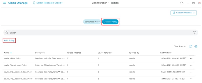
Step 3. Click Add Policy to bring up the Add Policy workflow.
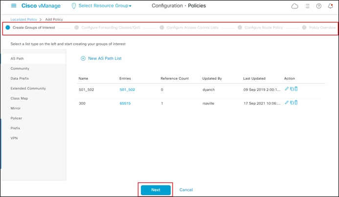
The Add Policy workflow has five steps – Create Groups of Interest, Configure Forwarding Classes/QoS, Configure Access Control Lists, Configure Route Policy, and Policy Overview. The localized policy workflow is a generic workflow which includes steps for creating the lists required for other steps in the workflow, creating and adding QoS policy to the overall localized policy, creating and adding data policy to the overall localized policy, and for creating and adding route policy to the overall localized policy. Since this guide only deals with localized route policy, we can skip the first three steps and proceed directly to the Configure Route Policy step within the workflow.
Step 4. Click the Next button three times, to get to the Configure Route Policy step in the workflow.
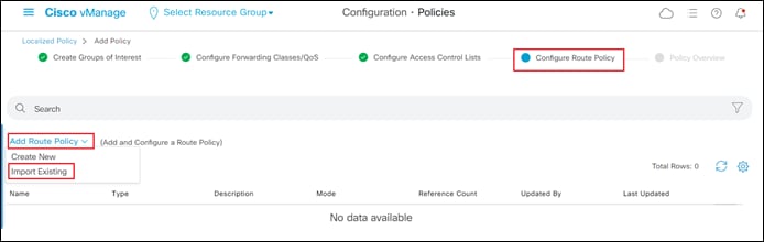
Step 5. From the drop-down menu under Add Route Policy select Import Existing to import the route policy created in the previous procedure.
The Import Existing Route Policy pop-up window will appear.
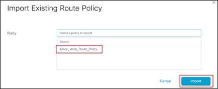
Step 6. In the drop-down menu adjacent to Policy select the route policy you created in the previous procedure.
Step 7. Click on the Import button to import the route policy into the localized policy.
Step 8. Click Next to continue to the last step in the workflow – Policy Overview.
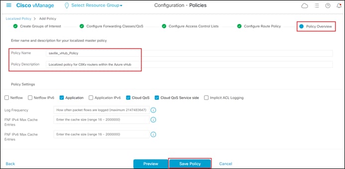
Step 9. In the open field adjacent to Policy Name, type in the name of the new localized policy.
For this guide, name of the localized data policy is Saville_vHub_Policy.
Step 10. In the open field adjacent to Policy Description, type in a description of the new localized policy.
Step 11. Click Save Policy to create the localized policy.
This completes the creation of the localized policy. To make use of the localized policy, it must be included within the device templates of the Catalyst 8000v routers functioning as NVAs within the Azure vHub.
Procedure 3. Add the Localized Policy to the Device Template
The following are the steps to add the localized policy to the device template for the Catalyst 8000v routers within the Azure vHub.
Step 1. From any screen within vManage, click the three bars in the upper left corner of the screen to bring up a navigation panel on the left side of the screen.
Step 2. In the navigation panel, select Configuration > Templates.
Step 3. Make sure the Device button is selected.
Locate the device template assigned to the Catalyst 8000v routers functioning as NVAs within the vHub.
Step 4. Click on the three dots (…) on the right side of the template to bring up the drop-down menu.
Step 5. From the drop-down menu select Edit.
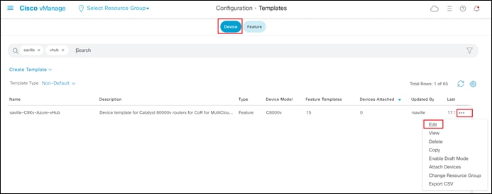
Step 6. Within the device template scroll down to the Additional Templates section.
Step 7. From the drop-down menu adjacent to Policy, select the localized policy created in the previous procedure.
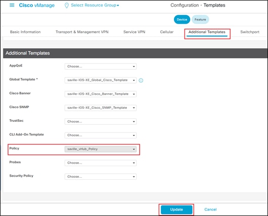
Step 8. Click Update to update template.
If you are updating a device template which is being used by Catalyst 8000v routers already deployed within an Azure vHub, you will be taken to the following screen.
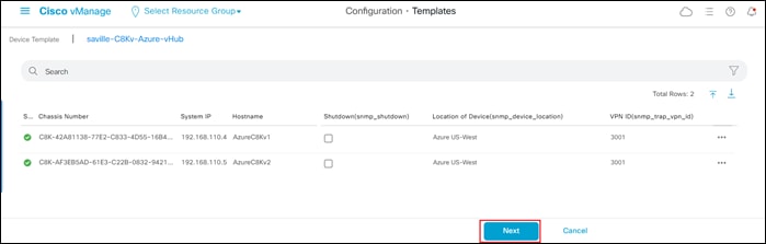
Step 9. On the next screen, click Configure Devices to push the template update to the Catalyst 8000v routers running within the Cloud Gateway.
Step 10. You will get a pop-up screen asking you to confirm. Click OK to confirm.
Step 11. After a few moments, you should see a screen indicating the update of the device template has succeeded.
It should be noted that the localized policy does not have to be configured and added to the device template after the Catalyst 8000v routers have been instantiated by Cisco Cloud onRamp for Multi-Cloud within the Azure vHub. The localized policy discussed within this guide can be included within the initial device template before the Catalyst 8000v routers are instantiated within Azure vHub.
If you SSH into one of the Catalyst 8000v routers functioning as NVAs within the Azure vHub, you will see that the following lines of configuration were added as a result of adding the Azure_vHub_Route_Policy to the saville_vHub_Policy and pushing the saville_vHub_Policy to the routers through vManage.
!
ip as-path access-list 300 permit 65515
!
~
!
ip prefix-list Azure_Host_vNets seq 5 permit 192.168.104.0/24
ip prefix-list Azure_Host_vNets seq 10 permit 192.168.105.0/24
!
~
!
route-map Azure_vHub_Route_Policy permit 1
match as-path 300
!
route-map Azure_vHub_Route_Policy permit 11
match ip address prefix-list Azure_Host_vNets
!
Procedure 4. Applying the Route Policy within the Localized Policy to a BGP Peer.
The previous procedure only pushes the policy configuration into the Cisco Catalyst 8000v routers, it does not actually apply the localized route policy included within the localized policy. Adding the localized policy to the device template simply adds the policy configuration to the Catalyst 8000v routers as they are created. At this point, the route policy is not applied to any BGP peers. Applying the route policy to BGP peers is accomplished within this procedure.
When applying the route policy to BGP peers within the Azure vHub, it is important to understand that the BGP peers do not exist on the Catalyst 8000v routers within the vHub until you have mapped a service VPN to a tag within the Intent Management workflow of Cisco Cloud onRamp for Multi-Cloud with Azure. Cisco Cloud onRamp for Multi-Cloud dynamically configures the BGP peers when you have mapped a service VPN to a tag which is assigned to one or more host vNets.
Therefore, in general, the order of applying an inbound BGP filter when using Cisco Cloud onRamp for Multi-Cloud with Azure is to first implement the intent within the Intent Management workflow. This will result in the mapping of one or more host vNets to the vHub, and the establishment of BGP peering between the vHub and the Cisco Catalyst 8000v routers functioning as NVAs within the Cloud Gateway. Once the BGP peering is established, you can SSH into the Catalyst 8000v routers to retrieve the BGP peering information. From the existing BGP peering information, the necessary route-map configuration can be configured within a CLI feature template. The feature template can then be added to the existing device template for the Cisco Catalyst 8000v routers and deployed to the existing Cloud Gateway routers. Note that any variables defined within the CLI template must be filled-in when deploying to the existing Catalyst 8000 routers within the Cloud Gateway.
Note also, that in general, when making any modifications to the mapping of tags to a service VPN within the Intent Management workflow, the CLI template should first be removed from the existing device template for the Cisco Catalyst 8000v routers. Removal of the CLI template could have a temporary negative impact on your deployment, since additional routes which were previously filtered out via the route-map could be injected into your network without the CLI template. Once the CLI template is removed, then modifications to the mapping of tags to service VPNs within the Intent Management workflow can be carried out.
The following are the steps to create a CLI template to add inbound route filtering of BGP updates.
Step 1. SSH into either one of the Cisco Catalyst 8000v routers deployed within the Cloud Gateway and retrieve the BGP configuration dynamically provisioned within the Intent Management workflow.
The following is the BGP configuration from the first Cisco Catalyst 8000v router (AzureC8Kv1) deployed as an NVA within the Azure vHub.
!
ip as-path access-list 15 permit _65515_
ip as-path access-list 25 permit .*
ip as-path access-list 300 permit 65515
!
~
!
ip route vrf 3000 192.168.112.68 255.255.255.255 192.168.112.225
ip route vrf 3000 192.168.112.69 255.255.255.255 192.168.112.225
!
~
!
route-map AZURE_CSR_NVA_ROUTE_POLICY deny 1
match as-path 15
!
route-map AZURE_CSR_NVA_ROUTE_POLICY permit 11
match as-path 25
!
route-map AZURE_CSR_NVA_ROUTE_POLICY deny 65535
!
~
!
router bgp 65010
bgp log-neighbor-changes
!
address-family ipv4 vrf 3000
redistribute omp
propagate-aspath
neighbor 192.168.112.68 remote-as 65515
neighbor 192.168.112.68 ebgp-multihop 5
neighbor 192.168.112.68 activate
neighbor 192.168.112.68 send-community both
neighbor 192.168.112.68 route-map AZURE_CSR_NVA_ROUTE_POLICY out
neighbor 192.168.112.69 remote-as 65515
neighbor 192.168.112.69 ebgp-multihop 5
neighbor 192.168.112.69 activate
neighbor 192.168.112.69 send-community both
neighbor 192.168.112.69 route-map AZURE_CSR_NVA_ROUTE_POLICY out
default-information originate
distance bgp 20 200 20
exit-address-family
!
timers bgp 60 18
!
From the dynamically generated BGP configuration, we can see that the two Azure BGP peers are 192.168.112.68 and 192.168.112.69. Alternatively, you can get the BGP peering information from the JSON view of Azure vHub itself. An example is shown in the following figure.
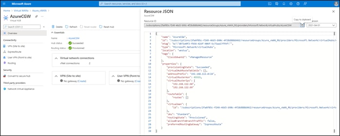
Step 2. From any screen within vManage, click the three bars in the upper left corner of the screen to bring up a navigation panel on the left side of the screen.
Step 3. In the navigation panel, select Configuration > Templates.
Step 4. Click the Features button at the top center of the screen to display the existing feature templates configured within vManage.
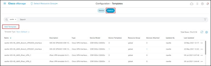
Step 5. Click Add Template to add a new feature template.
Step 6. In the navigation panel on the left side of the display that appears, scroll down the list of devices, and select C8000v.
The screen should change to reflect the available feature templates for Catalyst 8000v devices.
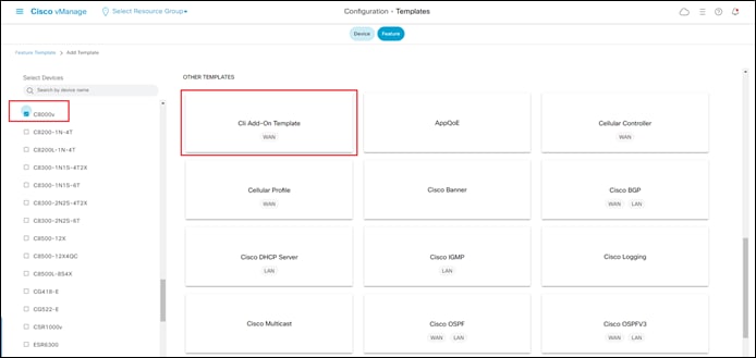
Step 7. Scroll down to the OTHER TEMPLATES section and select Cli Add-On Template.
This will bring up a blank copy of the Cli Add-On Template, as shown in the figure below.
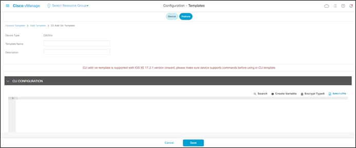
Step 8. Fill in the Template Name and Description.
For this guide the following template was created:
Template Name: saville-IOS-XE_Azure_vHub_CLI_Template
Description: CLI Template for Azure vHub Catalyst 8000v Routers
Step 9. Within the CLI CONFIGURATION section, type in the CLI configuration commands you wish to add to the Cisco Catalyst 8000v routers.
For this guide, the following configuration was added.
router bgp 65010
address-family ipv4 vrf 3000
neighbor 192.168.112.68 route-map Azure_vHub_Route_Policy in
neighbor 192.168.112.69 route-map Azure_vHub_Route_Policy in
exit-address-family
The Cli Add-On template should look as follows when filled in.
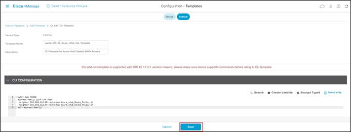
Step 10. Click Save to Save the Cli Add-On template.
This will bring you back to the Configurations Templates screen.
Step 11. Click the Device button at the top center of the Configurations Templates screen and locate the device template used to provision the two Cisco Catalyst 8000v routers within the Azure vHub.
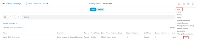
Step 12. Click the … button to the right of the device to bring up the drop-down menu and select Edit.
Step 13. Scroll down to the Additional Templates section
Step 14. From the drop-down menu adjacent to Cli Add-On Template, select the Cli Add-On template you just configured and click Update.
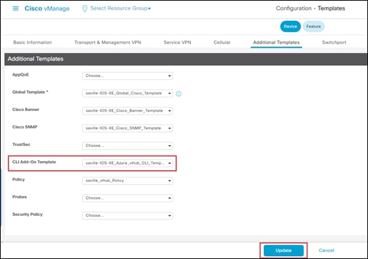
This will take you through the steps to push the updated device template to the Cisco Catalyst 8000v routers already deployed and running within the Azure vHub. A screen similar to the following will appear.
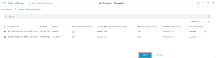
Step 15. Since you have not defined any new variables within the Cli Add-On template, click Next to continue with the deployment.
| Technical Note |
| You can add variables to a Cli Add-On template using Jinja-style formatting. Simply place the variable name within curly braces, as shown {{ variable_name }}. When you add variables within the CLI Add-On template, you will have to have to fill in the variables before deploying the template. Click on the three dots … to the right of each device to bring up the drop-down menu. The only selection in the menu is Edit Device Template. When you select this choice, a pop-up menu will appear, allowing you to fill-in the values for the variable names you created within the CLI Add-on template. |
Step 16. In the screen which appears, click Configure Devices.
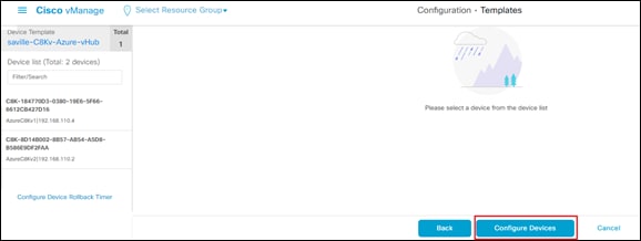
A pop-up screen will appear, asking you to confirm changes on the two devices.
Step 17. Click the check box to confirm the changes to the Cisco Catalyst 8000v routers running within the Azure vHub and click OK to push the configuration changes.
Step 18. After a few minutes, the status should appear as Successful.
You can verify that the inbound route filter has been applied by establishing an SSH sessions to the Cisco Catalyst 8000v routers running as NVAs within the Azure vHub and viewing the BGP configuration. The outbound route filter created through the deployment of localized route policy should now be applied to both BGP peers, as shown below.
router bgp 65010
bgp log-neighbor-changes
!
address-family ipv4 vrf 3000
redistribute omp
propagate-aspath
neighbor 192.168.112.68 remote-as 65515
neighbor 192.168.112.68 ebgp-multihop 5
neighbor 192.168.112.68 activate
neighbor 192.168.112.68 send-community both
neighbor 192.168.112.68 route-map Azure_vHub_Route_Policy in
neighbor 192.168.112.68 route-map AZURE_CSR_NVA_ROUTE_POLICY out
neighbor 192.168.112.69 remote-as 65515
neighbor 192.168.112.69 ebgp-multihop 5
neighbor 192.168.112.69 activate
neighbor 192.168.112.69 send-community both
neighbor 192.168.112.69 route-map Azure_vHub_Route_Policy in
neighbor 192.168.112.69 route-map AZURE_CSR_NVA_ROUTE_POLICY out
default-information originate
distance bgp 20 200 20
exit-address-family
!
Process: Monitor Cisco Cloud onRamp for Multi-Cloud
When you monitor Cisco Cloud onRamp for Multi-Cloud, you can view the following:
● The state of the Cloud Gateway
● The connectivity state of each host vNet
● Detailed traffic statistics for the IPsec VPN connections between the transit VPC and each host VPC
Procedure 1. View the State of the Cloud Gateway
Step 1. From any screen within vManage, click the three bars in the upper left corner of the screen to bring up a navigation panel on the left side of the screen.
Step 2. In the navigation panel, select Configuration > Cloud onRamp for Multi-Cloud.
Step 3. Make sure the Cloud button at the top of the screen is selected.
This will bring you to the initial Cisco Cloud onRamp for Multi-Cloud screen, as shown below.
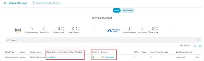
Within the initial Cisco Cloud onRamp for Multi-Cloud screen, you can see the Health of the Cloud Gateway. In the figure above the Health is indicated with a green check mark. Adjacent to the green check mark, you can see that both Cisco 8000v SD-WAN routers functioning as NVAs within the Cloud Gateway are running and reachable to vManage.
Step 4. Click on the name of your Cloud Gateway under the Cloud Gateway Name/Azure WAN Hub column to bring up additional details, as shown in the figure below.
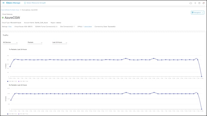
Additional details regarding the Cloud Gateway are displayed in four panels. The Traffic panel, which is useful for monitoring traffic, as well as errors and drops, across the SD-WAN fabric to the Cloud Gateway, has three drop-down menus near the top of the panel.
● The drop-down menu on the left can be used to display traffic for both Cisco Catalyst 8000v routers functioning as NVAs within the vHub (All Devices) or individually, based on the system IP address of the device.
● The center drop-down menu can be used to change the type of date displayed within the graphs. The choices within the drop-down menu are as follows:
◦ Kbps - Throughput in kilobits per second seen within each aggregation interval over the timeframe selected
◦ Packets - Total packets seen within each aggregation interval over the timeframe selected
◦ Octets - Total bytes seen within each aggregation interval over the timeframe selected
◦ Errors - Total errors seen within each aggregation interval over the timeframe selected
◦ Drops - Total drops seen within each aggregation interval over the timeframe selected
◦ Pps - Throughput in packets per second seen within each aggregation interval over the timeframe selected
● The drop-down menu on the right can be used to control the timeframe over which the graphical data is displayed. The choices within the drop-down menu are as follows:
◦ Last 1 hour
◦ Last 3 hours
◦ Last 6 hours
◦ Last 12 hours
◦ Last 24 hours
◦ Last 7 days
Shorter overall timeframes result in shorter aggregation intervals over which the data is displayed.
The Cloud Gateway Devices panel provides a quick visual health check of each of the Cisco Catalyst 8000v routers functioning as NVAs within the Cloud Gateway, as well as additional information regarding the instances.
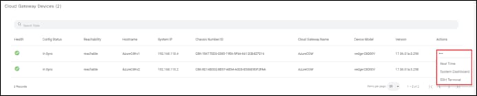
Clicking on the three dots (…) under the Actions column for one of the Catalyst 8000v routers will bring up a drop-down menu with the following choices:
● Real Time – This provides a quick link to the same information that can be found by navigating to Monitor > Network > Device Name > Real Time within the vManage graphical user interface.
● System Dashboard – This provides a quick link to the same information that can be found by navigating to Monitor > Network > Device Name > System Status within the vManage graphical user interface.
● SSH Terminal – This provides a quick link to the SSH terminal that can be found by navigating to Tools > SSH Terminal > Device Name.
The Associated Branch Devices panel provides a quick visual health check of other SD-WAN routers which have tunnels established over the SD-WAN fabric to the Cisco Catalyst 8000v routers functioning as NVAs within the Cloud Gateway.
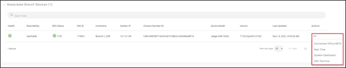
In the figure above, a single CSR 1000v branch router (Branch-1_CSR) is connected via 2 SD-WAN tunnels (one to each Catalyst 8000v router within the Cloud Gateway) – based upon the BFD Status indicating 2 BFD sessions currently up.
Clicking on the three dots (…) under the Actions column for any of the branch routers will bring up a drop-down menu with the following choices:
● Connected VPCs/vNets – This brings up a pop-up screen showing the same information as displayed in the Associated VPCs/vNETs panel discussed next.
● Real Time – This provides a quick link to the same information that can be found by navigating to Monitor > Network > Device Name > Real Time within the vManage graphical user interface.
● System Dashboard – This provides a quick link to the same information that can be found by navigating to Monitor > Network > Device Name > System Status within the vManage graphical user interface.
● SSH Terminal – This provides a quick link to the SSH terminal that can be found by navigating to Tools > SSH Terminal > Device Name.
The Associated VPCs/vNETs panel provides information regarding the names of the host vNets which are accessible through the service VPN (VPN id) extended from the Cisco Catalyst 8000v routers functioning as NVAs into the Azure vHub.
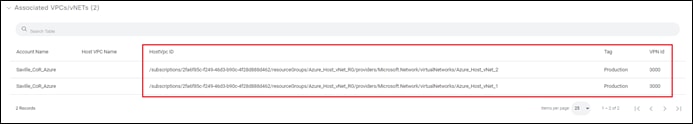
In the figure above, Host_vNet_1 and Host_vNet_2 are both reachable from service VPN 3000.
This section presents alternative designs to the automation provided by Cisco Cloud onRamp for Multi-Cloud with Azure. The primary reasons for consideration of these designs are as follows:
● Support for ExpressRoute circuits as SD-WAN transport interfaces.
● The requirement for more than two Catalyst 8000v routers for additional scale. As of software release 17.6.1 / 20.6.1 Cisco Cloud onRamp for Multi-Cloud currently instantiates a single pair of Catalyst 8000v routers as NVAs within the vHub.
Deployment steps for these designs will not be provided. Instead, this section will outline at a high level how the additional functionality can be accommodated within a Cisco SD-WAN deployment.
Azure ExpressRoute Circuits Terminated on the vHub as SD-WAN Transports
The following figure shows how Cisco Cloud onRamp for Multi-Cloud can accommodate Azure ExpressRoute circuits as SD-WAN transports.
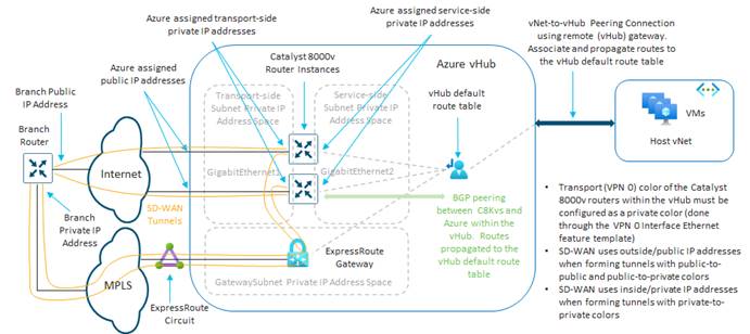
With this option, you must manually add an ExpressRoute gateway to the vHub in which you will be instantiating the Cisco Catalyst 8000v routers as NVAs. An example is shown in the following figure.
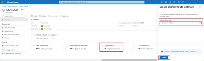
Once you have added an ExpressRoute gateway to the vHub, you must make sure your ExpressRoute circuit is associated with the ExpressRoute gateway. Azure allows up to 8 ExpressRoute circuits per peering location to be associated with each vHub.
Within Cisco Cloud onRamp for Multi-Cloud with Azure, there is no change to the current functionality. All that is required is for you to specify a private color for the SD-WAN transport (VPN 0) interface (also referred to as the transport location or TLOC) when you instantiate the Cisco Catalyst 8000v routers within the vHub. This is done through the VPN0 Interface Ethernet feature template which is added to the device template used to instantiate the SD-WAN routers within the vHub.
Within this guide, the color of the transport interface is specified as a variable within each VPN0 Interface Ethernet feature template for each of the Cisco Catalyst 8000v routers. This was shown in Tables 1 and 2 earlier within this document.
This method works because of the following rules that Cisco SD-WAN follows when establishing IPsec VPN tunnels based on the transport location (TLOC) color.
● SD-WAN devices use outside/public IP addresses when forming tunnels with public-to-public and public-to-private colors
● SD-WAN devices use inside/private IP addresses when forming tunnels with private-to-private colors
| Technical Note |
| Transport Locators (TLOCs) refer to the WAN transport (VPN 0) interfaces by which SD-WAN routers connect to the underlay network. Each TLOC is uniquely identified through a combination of the system IP address of the SD-WAN router, the color of the WAN interface, and the transport encapsulation (GRE or IPsec). The Cisco Overlay Management Protocol (OMP) is used to distribute TLOCs (also known as TLOC routes), SD-WAN overlay prefixes (also known as OMP routes), and other information between SD-WAN routers. It is through TLOC routes that SD-WAN routers know how to reach each other and establish IPsec VPN tunnels with each other. SD-WAN routers and/or controllers (vManage, vSmart, or vBond) may sit behind Network Address Translation (NAT) devices within the network. When an SD-WAN router authenticates to a vBond controller, the vBond controller will learn both the private IP address/port number and the public IP address/port number settings of the SD-WAN router during the exchange. vBond controllers act as Session Traversal Utilities for NAT (STUN) servers, allowing SD-WAN routers to discover mapped and/or translated IP addresses and port numbers of their WAN transport interfaces. On SD-WAN routers every WAN transport is associated with a public and private IP address pair. The private IP address is considered to be the pre-NAT address. This is IP address assigned to the WAN interface of the SD-WAN router. Although this is considered to be the private IP address, this IP address can be either part of the publicly routable IP address space or part of the IETF RFC 1918 non-publicly routable IP address space. The public IP address is considered to be the post-NAT address. This is detected by the vBond server when the SD-WAN router initially communicates and authenticates with the vBond server. The public IP address can also be either part of the publicly routable IP address space or part of the IETF RFC 1918 non-publicly routable IP address space. In the absence of NAT, both the public and private IP addresses of the SD-WAN transport interface are the same. TLOC colors are statically defined keywords used to identify individual WAN transports on each SD-WAN router. Each WAN transport on a given SD-WAN router must have a unique color. Colors are also used to identify an individual WAN transport as being either public or private. The colors metro-ethernet, mpls, and private1, private2, private3, private4, private5, and private6 are considered private colors. They are intended for use in private networks or places where there is no NAT. The colors are 3g, biz-internet, blue, bronze, custom1, custom2, custom3, default, gold, green, lte, public-internet, red, and silver are considered public colors. They are intended to be used in public networks or in places with public IP addressing of the WAN transport interfaces, either natively or through NAT. Color dictates the use of either private or public IP addresses when communicating through the control and data planes. When two SD-WAN routers attempt to communicate with each other, both using WAN transport interfaces with private colors, each side will attempt to connect to the remote router’s private IP address. If one or both sides are using public colors, then each side will attempt to connect to the remote router’s public IP address. An exception to this is when the Site IDs of two devices are the same. When the Site IDs are the same, but the colors are public, the private IP addresses will be used for communication. This may occur for SD-WAN routers attempting to communicate to a vManage or vSmart controller located within the same site. Note that SD-WAN routers do not, by default, establish IPsec VPN tunnels between each other when they have the same Site IDs. |
With the TLOC color specified as a private color, SD-WAN tunnels will form over the Internet using public IP addresses. SD-WAN tunnels will also form (using the same interface) over the ExpressRoute circuits using private IP addresses. This method assumes the following:
● The ExpressRoute circuit is mapped to a managed service, such as MPLS shown in the Figure 72 above, or terminated within a colocation partner data center.
● The managed service WAN circuit or colocation partner connection is connected to the WAN transport (VPN 0) interface of the head-end / regional SD-WAN routers, as shown in Figure 72 above.
● The WAN transport (VPN 0) interface of the Cisco Catalyst 8000v routers functioning as NVAs within the vHub have IP reachability (via route) to the WAN transport (VPN) interface of the head-end / regional SD-WAN routers to which the managed service or colocation partner circuits connect. This is necessary for the SD-WAN tunnels to form across the ExpressRoute circuits.
Note that with this design option, there is still only a single WAN transport (VPN 0) interface configured on the Cisco Catalyst 8000v routers instantiated as NVAs within the Azure vHub.
Azure ExpressRoute Circuits Terminated on a Transit vNet with Cisco SD-WAN Routers
The second option for accommodating Azure ExpressRoute circuits as SD-WAN transports, involves the use of a transit vNet. Since the use of a transit vNet is outside the Cisco Cloud onRamp for Multi-Cloud workflow, this design must be instantiated by custom automation or manually. Note however that this method can accommodate Cisco Catalyst 8000v, Cisco CSR 1000v, and Cisco vEdge Cloud routers within the Azure transit vNet.
There are two variations to this design. With both variations of this design option, you must first create a transit vNet. The transit vNet will require a minimum of 4 subnets as follows:
● An Internet_Transport subnet for the Internet WAN Transport (VPN 0) interfaces (GigabitEthernet1) of the SD-WAN routers.
● An ExpressRoute_Transport subnet for the ExpressRoute WAN Transport (VPN 0) interfaces (GigabitEthernet3) of the SD-WAN routers.
● A Service subnet for the service VPN interfaces (GigabitEthernet2) of the SD-WAN routers.
● A GatewaySubnet which is mandatory for any Virtual Network Gateways (VNGs) created within Azure.
An ExpressRoute Virtual Network Gateway (VNG) must be created within the transit vNet, and your ExpressRoute circuit associated with the gateway. This method assumes the following:
● The ExpressRoute circuit is mapped to a managed service, such as MPLS shown in the Figure 74 below, or terminated within a colocation partner data center.
● The managed service WAN circuit or colocation partner connection is connected to the WAN transport (VPN 0) interface of the head-end / regional SD-WAN routers, as shown in Figure 74 below.
● The ExpressRoute WAN transport (VPN 0) interface (GigabitEthernet3) of the Cisco SD-WAN routers have IP reachability to the WAN transport (VPN) interface of the head-end / regional SD-WAN routers to which the managed service or colocation partner circuits connect. This is necessary for the SD-WAN tunnels to form across the ExpressRoute circuits.
Note that the TLOC color of the ExpressRoute WAN transport (VPN 0) should be a private color if private IP addressing is being used across the ExpressRoute circuit / managed service network. With this design option, there are two WAN transport (VPN 0) interfaces configured on the SD-WAN routers instantiated within the transit vNet.
The two variations of this design are based upon how the transit vNet connects to the Azure vHub. The first variation involves the use of vNet-to-vHub peering with static/user-defined routes. The second variation involves the use of IPsec VPN connections between the SD-WAN routers within the transit vNet and a VPN Virtual Network Gateway (VNG) within the vHub.
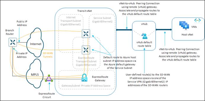
With the first variation, vNet-to-vHub peering is configured between the Azure vHub and the transit vNet. Within the peering, the transit vNet is configured to use the remote VNG / route server within the vHub. Routes are associated and propagated to the default route table of the vHub. This ensures the IP address space of the transit vNet is advertised into the vHub and propagated into the host vNets. Since there is no active routing protocol to propagate the OMP routes within the SD-WAN network known to the SD-WAN routers within the transit vNet, into Azure, one or more user-defined routes (UDRs) must be configured within the default route table of the Azure vHub. The UDRs point to the IP address of the Service subnet interface (GigabitEthernet2) of one of the SD-WAN routers within the transit vNet. Likewise, within the SD-WAN routers in the transit vNet, one or more static routes to the host vNet IP address space (and optionally the vHub IP address space) needs to be configured. The static route points to the Azure default gateway IP address of the Service subnet interface (GigabitEthernet3) of each of the SD-WAN routers.
Since this method relies on static routes, and in particular the UDRs that point to only one of the SD-WAN routers, there is no load-balancing of traffic across multiple paths and multiple SD-WAN routers. The throughput of this design is limited to the throughput of a single SD-WAN router within the transit vNet. Further, should that SD-WAN router go down, the UDRs would have to be manually changed to point to the other SD-WAN router. For these reasons, this variation of the transit vNet design is not considered highly favorable.
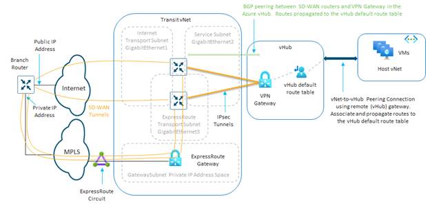
With the second variation, a VPN Virtual Network Gateway (VNG) is instantiated within the Azure vHub. IPsec connections are configured between the SD-WAN routers within the transit vNet and the VPN gateway within the vHub. The IPsec connections extend a single SD-WAN service VPN to the VPN gateway, similar to how Cisco Cloud onRamp for IaaS with Azure extends a single SD-WAN service VPN to a host vNet. BGP peering is established between the SD-WAN routers within the transit vNet and the VPN gateway within the Azure vHub, again similar to how Cisco Cloud onRamp for IaaS with Azure operates. The routes received at the VPN Gateway via the BGP peering with the SD-WAN routers are associated and propagated into the default route table of the Azure vHub. This ensures the propagation of the routes from the SD-WAN overlay all the way through to the host vNets.
Since each SD-WAN router establishes IPsec tunnels and BGP peering with the VPN gateway within the vHub, traffic can be load-balanced across the IPsec connections and the SD-WAN routers. Should an SD-WAN router fail, the traffic will utilize the other SD-WAN router. Finally, additional SD-WAN routers can be instantiated within the transit vNet, additional IPsec connections configured, and additional BGP peerings established to add additional scale to the design.
Appendix A: Changes from Previous Versions
Second revision. Appendix F: Integration with a Service vNet Hosting a Load-Balancer and Firewalls added.
Appendix B: Hardware and Software Used for Validation
This guide was validated using the following hardware and software.
Table 8. Hardware and Software for Validation
| Functional Area |
Product |
Software version |
| Azure Cloud Gateway Routers |
Cisco Catalyst 8000v |
17.06.01 |
| SD-WAN Control |
Cisco vBond, vSmart, and vManage |
20.6.1 |
Appendix C: Cisco Catalyst 8000v Router Configuration Template Summary
This section summarizes the feature and device templates for the Cisco IOS XE SD-WAN routers for this deployment guide.
| Technical Note |
| Although the templates discussed within this section are generic to Cisco IOS-XE SD-WAN devices, Cisco Cloud onRamp for IaaS with Azure only supports instantiation of Cisco Catalyst 8000v routers within the Cloud Gateway. |
The naming of the device and feature templates within this deployment guide follows a convention which reflects the following:
● The administrator who created the template
● The device type (Cisco IOS XE SD-WAN device or vEdge device) for which the template should be applied.
● The function of the template
Follow whatever convention is appropriate for your organization.
Azure vHub Catalyst 8000v Device Template
The following table summarizes the device template for the Cisco Catalyst 8000v routers deployed within the Azure vHub.
Device Model: C8000v
Device Role: SDWAN Edge
Template Name: saville-C8Kv-Azure-vHub
Description: Device template for Catalyst 8000v routers using Cisco Cloud onRamp for Multi-Cloud in an Azure Cloud Gateway
Table 9. Azure vHub Catalyst 8000v Device Template: saville-C8Kv-Azure-vHub
| Template Category |
Template Type |
Template Name |
| Basic Information |
Cisco System |
saville-IOS-XE_Cisco_System_Template |
|
|
Cisco Logging |
saville-IOS-XE_Logging_Template |
|
|
Cisco NTP |
saville-IOS-XE_Cisco_NTP_Template |
|
|
Cisco AAA |
saville-IOS-XE_Cisco_AAA_Template |
|
|
Cisco BFD |
saville-IOS-XE_BFD_Template |
|
|
Cisco OMP |
saville-IOS-XE _OMP |
|
|
Cisco Security |
saville-IOS-XE_Cisco_Security_Template |
| Transport & Management VPN |
Cisco VPN 0 |
saville-IOS-XE_VPN0_Template |
|
|
Cisco VPN Interface Ethernet |
saville-IOS-XE_Azure_vWAN_VPN0_INTF_GE1_V01_Template |
|
|
Cisco VPN 512 |
saville-IOS-XE_VPN512_Template |
| Service VPN |
Cisco VPN |
saville-IOS-XE_VPN3001_Template |
|
|
Cisco VPN Interface Ethernet |
saville-IOS-XE_VPN3001_Lo0 |
| Additional Templates |
Cisco Global |
saville-IOS-XE_Global_Cisco_Template |
|
|
Cisco Banner |
saville-IOS-XE_Cisco_Banner_Template |
|
|
Cisco SNMP |
saville-IOS-XE_Cisco_SNMP_Template |
|
|
Policy |
saville_4Q_Localized_Data_Policy (QoS policy) or saville_vHub_Policy (BGP inbound route filtering and QoS policy) |
|
|
CLI Add-On Template |
saville-IOS-XE_Azure_vHub_CLI_Template |
The above device template is created from feature templates. The feature templates are modified copies of the default feature templates found within the Default_Azure_vWAN_C8000V_Template_V01 default device template.
Azure vHub Catalyst 8000v Feature Templates
The following are the feature templates included within the saville-C8Kv-Azure-vHub device template applied to the Cisco Catalyst 8000v routers instantiated within the Azure Cloud Gateway.
IOS XE SD-WAN Cisco System Feature Template
Devices: All ASR1K, ISR4K, C8K C1100, ISR1100 (Cisco OS), C8Kv, CSR1Kv, ISRv
ENCS-6300, IR1K, IR8340, & CG Series
Template: Basic Information / Cisco System
Template Name: saville-IOS-XE_Cisco_System_Template
Description: IOS XE SD-WAN Cisco System feature template
Table 10. IOS XE SD-WAN Cisco System Feature Template Settings
| Section |
Parameter |
Type |
Variable/Value |
| Basic Configuration |
Site ID |
Device Specific |
system_site_id |
|
|
System IP |
Device Specific |
system_system_ip |
|
|
Hostname |
Device Specific |
system_host_name |
|
|
Device Groups |
Device Specific |
system_device_groups |
|
|
Console Baud Rate (bps) |
Device Specific |
system_console_baud_rate |
| GPS |
Latitude |
Device Specific |
system_latitude |
|
|
Longitude |
Device Specific |
system_longitude |
| Advanced |
Port Hopping |
Device Specific |
system_port_hop |
|
|
Port Offset |
Device Specific |
system_port_offset |
|
|
Gateway Tracking |
Device Specific |
System_track_default_gateway |
All other settings not listed within the above table are left at their defaults.
IOS XE SD-WAN Logging Feature Template (Optional)
Devices: All ASR1K, ISR4K, C8K C1100, ISR1100 (Cisco OS), C8Kv, CSR1Kv, ISRv
ENCS-6300, IR1K, & IR8340 Series
Template: Basic Information / Cisco Logging
Template Name: saville-IOS-XE_ Logging_Template
Description: IOS XE SD-WAN Cisco Logging Template
Table 11. IOS XE SD-WAN Cisco Logging Feature Template Settings
| Section |
Parameter |
Type |
Variable/Value |
| Server |
Hostname/IPv4 Address |
Global |
logging_server_ip_addr |
|
|
VPN ID |
Device Specific |
logging_server_vpn |
|
|
Source Interface |
Global |
loopback0 |
All other settings not listed within the above table are left at their defaults. Central logging of information from the Cisco Catalyst 8000v routers within the Azure vHub, to a server within the campus may provide additional information when monitoring and/or troubleshooting issues related to connectivity to the Azure host vNets. However, logging information across the SD-WAN IPsec VPN connections between the campus and the vHub will also increase Azure data transfer costs. You should balance out the requirement for central logging with the additional costs and decide appropriately.
IOS XE SD-WAN Cisco NTP Feature Template (Optional)
Devices: All ASR1K, ISR4K, C8K C1100, ISR1100 (Cisco OS), C8Kv, CSR1Kv, ISRv
ENCS-6300, IR1K, & IR8340 Series
Template: Basic Information / Cisco NTP
Template Name: saville-IOS-XE_Cisco_NTP_Template
Description: IOS XE SD-WAN Cisco NTP feature template
Table 12. IOS XE SD-WAN Cisco NTP Feature Template Settings
| Section |
Parameter |
Type |
Variable/Value |
| Server |
Hostname/IP Address |
Device Specific |
vpn0_ntp_server_host |
All other settings not listed within the above table are left at their defaults. When a Cisco Catalyst 8000v router first powers up within Azure, it should get its time from the physical server. However, being a virtual machine, the Catalyst 8000v router time may drift. Because of this, you may wish to sync the Catalyst 8000v router time to an NTP server.
With Cisco Cloud onRamp for Multi-Cloud, the Cisco Catalyst 8000v routers within the Azure vHub must be configured such that interface GigabitEthernet1 is part of VPN 0 (transport VPN). Interface GigabitEthernet1 will automatically get its IP address via DHCP. The Azure DHCP server which allocates the IP address to GigabitEthernet1 will also provide the DNS server IP address. Therefore, a hostname can be configured if the hostname can be translated to an IP address by the Azure DNS server. For this deployment guide the NTP server time.nist.gov was used.
You should be careful to use only known and trusted NTP servers. Disruptions to time synchronizations can affect the ability of the Cisco Catalyst 8000v routers within the vHub to connect to the vBond, vManage, and vSmart; as well as the ability to establish IPsec connections to other Cisco SD-WAN Edge routers.
IOS XE SD-WAN Cisco AAA Feature Template
Devices: All ASR1K, ISR4K, C8K C1100, ISR1100 (Cisco OS), C8Kv, CSR1Kv, ISRv
ENCS-6300, IR1K, & IR8340 Series
Template: Basic Information / Cisco AAA
Template Name: saville-IOS-XE_Cisco_AAA_Template
Description: IOS XE SD-WAN Cisco AAA feature template
Table 13. IOS XE SD-WAN Cisco AAA Feature Template Settings
| Section |
Parameter |
Type |
Variable/Value |
| Local |
User/admin/Password |
Global |
<your admin password> |
|
|
User/admin/Privilege |
Global |
15 |
| Authentication Order |
ServerGroups priority order |
Global |
local |
All other settings not listed within the above table are left at their defaults. This deployment guide uses local authentication for simplicity. For production environments you may wish to consider using a centralized AAA server with an authentication protocol such as RADIUS or TACACS+.
IOS XE SD-WAN Cisco OMP Feature Template
Devices: C8Kv & CSR1Kv
Template: Basic Information / Cisco OMP
Template Name: saville-IOS-XE_OMP
Description: IOS XE SD-WAN Cisco OMP Template
Table 14. IOS XE SD-WAN Cisco OMP Feature Template Settings
| Section |
Parameter |
Type |
Variable/Value |
| Basic configuration |
Number of Paths Advertised per Prefix |
Global |
16 |
|
|
ECMP Limit |
Global |
16 |
| Advertise |
BGP |
Global |
On |
All other settings not listed within the above table are left at their defaults. Since the Catalyst 8000v routers within the Cloud Gateway will establish BGP peering to the default route table within the Azure vHub, BGP redistribution into OMP is necessary to route the prefixes learned from the Azure vHub to the rest of the SD-WAN fabric. The number of paths advertised per prefix and the ECMP limit for OMP has been increased from the default of 4 to the maximum of 16. Adjust this as necessary in your network.
| Technical Note |
| Re-distribution of BGP routes into OMP can be controlled both within the OMP feature template and the VPN template for the given service VPN. For IOS XE devices the behavior appears to be a logical OR as of vManage release 20.1.1 and higher. |
IOS XE SD-WAN Cisco BFD Feature Template
Devices: All ASR1K, ISR4K, C8K C1100, ISR1100 (Cisco OS), C8Kv, CSR1Kv, ISRv
ENCS-6300, IR1K, & IR8340 Series
Template: Basic Information / Cisco BFD Template
Template Name: saville-IOS-XE_BFD_Template
Description: IOS XE SD-WAN Cisco BFD feature template
Table 15. IOS XE SD-WAN Cisco BFD Feature Template Settings
| Section |
Parameter |
Type |
Variable/Value |
| Basic Configuration |
Poll Interval |
Device Specific |
bfd_poll_interval |
| Color (Biz Internet) |
Color |
Device Specific |
bfd_color |
|
|
Hello Interval (milliseconds) |
Device Specific |
bfd_color_hello_interval |
All other settings not listed within the above table are left at their defaults. The default BFD hello interval is 1,000 milliseconds. The BFD hello interval controls how fast the network converges in the case of an IPsec tunnel failure. The shorter the BFD hello interval, generally the faster the network recognizes a failure of one of the Catalyst 8000v routers within the vHub and selects an alternate path. However, a shorter BFD hello interval also results in more control traffic from each Cisco SD-WAN Edge router within each branch site to the vHub Cisco Catalyst 8000v routers. This adds to the Azure data transfer charges.
| Technical Note |
| As of vManage release 20.6 / 17.6 Cisco Cloud onRamp for Multi-Cloud with Azure provisions a single Internet-facing transport (VPN 0) interface on each Catalyst 8000v routers within the Cloud Gateway, using the GigabitEthernet1 interface. ExpressRoute-facing transport interfaces are currently not supported within the Cisco Cloud onRamp for Multi-Cloud workflow. |
For this deployment guide, the BFD poll interval and BFD hello interval for the BFD color have all been configured as device specific variables. This allows the BFD poll interval and BFD hello interval to be set via the device template when Catalyst 8000v routers are instantiated within the Cloud Gateway. You should select the appropriate BFD poll interval and hello interval to balance the requirement for fast convergence against the cost of additional data transfer charges in your deployment.
IOS XE SD-WAN Cisco Security Feature Template
Devices: All ASR1K, ISR4K, C8K C1100, ISR1100 (Cisco OS), C8Kv, CSR1Kv, ISRv
ENCS-6300, IR1K, & IR8340 Series
Template: Basic Information / Cisco Security
Template Name: saville-IOS-XE_Cisco_Security_Template
Description: IOS XE SD-WAN Cisco Security feature template
Table 16. IOS XE SD-WAN Cisco Security Feature Template Settings
| Section |
Parameter |
Type |
Variable/Value |
| Basic configuration |
Replay window |
Global / drop-down |
4096 |
All other settings not listed within the above table are left at their defaults. For this deployment guide, the anti-replay window was increased to its maximum value of 4096 packets.
IOS XE SD-WAN VPN 0 Feature Template
Devices: C8Kv & CSR1Kv
Template: VPN / Cisco VPN
Template Name: saville-IOS-XE_VPN0_Template
Description: VPN 0 Template for IOS-XE devices
Table 17. IOS XE SD-WAN VPN0 Feature Template Settings
| Section |
Parameter |
Type |
Variable/Value |
| Basic Configuration |
VPN |
Global |
0 |
|
|
Name |
Global |
Transport Interface |
All other settings not listed within the above table are left at their defaults.
IOS XE SD-WAN VPN 0 Interface Ethernet Feature Template
Devices: C8Kv & CSR1Kv
Template: VPN / Cisco VPN Interface Ethernet
Template Name: saville-IOS-XE-Azure_vWAN_C8000V_VPN0_INTF_GE1_V01
Description: VPN 0 Interface GigabitEthernet1 template for Azure vHub C8Kv or CSRv
Table 18. IOS XE SD-WAN VPN0 Interface GigabitEthernet1 Feature Template Settings (Internet)
| Section |
Parameter |
Type |
Variable/Value |
| Basic Configuration |
Shutdown |
Global |
No |
|
|
Interface Name |
Global |
GigabitEthernet1 |
|
|
Description |
Global |
VPN0 Internet Interface |
| IPv4 Configuration |
IPv4 Address |
Radio Button |
Dynamic |
|
|
Bandwidth Upstream |
Device Specific |
vpn0_inet_int_bandwidth_up |
|
|
Bandwidth Downstream |
Device Specific |
vpn0_inet_int_bandwidth_down |
| Tunnel |
Tunnel Interface |
Global |
On |
|
|
Color |
Device Specific |
vpn0_inet_int_tunnel_color |
|
|
Restrict |
Device Specific |
vpn0_inet_tunnel_color_restrict |
|
|
Allow Service>All |
Global |
Off |
|
|
Allow Service>SSH |
Global |
On |
| Tunnel>Advanced Options>Encapsulation |
IPsec |
Global |
On |
|
|
IPsec Preference |
Device Specific |
vpn0_inet_tunnel_ipsec_preference |
| ACL/QoS |
QoS Map |
Device Specific |
qos_map |
All other settings not listed within the above table are left at their defaults.
For Cisco Cloud onRamp for Multi-Cloud with Azure, a single Internet-facing transport (VPN 0) interface is provisioned. This interface must be specified as GigabitEthernet1 and is therefore configured as the Interface Name within the template, rather than specified as a variable. The IP address of the GigabitEthernet1 is specified as dynamic, allowing Azure to automatically provision an IP address to the interface via DHCP.
The Bandwidth Upstream and Bandwidth Downstream variables do not actually specify the upstream and downstream bandwidth of the Internet transport connection. Instead, they are used more for monitoring the utilization of the transport link. Cisco SD-WAN routers will generate notifications which are sent to vManage when the actual bandwidth utilization exceeds 85% of the bandwidth specified within the Bandwidth Upstream and Bandwidth Downstream variables. These can be used to alert you to potential congestion occurring in your network.
The tunnel Color and Restrict settings have been defined as variables for this deployment guide. This was done simply to control which campus and branch locations form tunnels to the Catalyst 8000v routers within the Cloud Gateway. Set these variables as necessary within your deployment.
Finally, although there is only one transport (VPN 0) connection defined within the Catalyst 8000v routers within the Cloud Gateway, the IPsec Preference setting has been specified as a variable as well. Set this variable as necessary within your deployment.
IOS XE SD-WAN VPN 512 Feature Template
Devices: C8Kv & CSR1Kv
Template: VPN / Cisco VPN
Template Name: saville-IOS-XE_VPN512_Template
Description: IOS-XE VPN 512 Management feature template
Table 19. IOS XE SD-WAN VPN512 Feature Template Settings
| Section |
Parameter |
Type |
Variable/Value |
| Basic Configuration |
VPN |
Global |
512 |
|
|
Name |
Global |
Management VPN |
All other settings not listed within the above table are left at their defaults.
IOS XE SD-WAN VPN 3001 Feature Template (Optional)
Devices: C8Kv & CSR1Kv
Template: VPN / Cisco VPN
Template Name: saville-IOS-XE_VPN3001_Template
Description: IOS-XE VPN 3001 Service Template
Table 20. IOS XE SD-WAN VPN3001 Feature Template Settings
| Section |
Parameter |
Type |
Variable/Value |
| Basic Configuration |
VPN |
Global |
3001 |
|
|
Name |
Global |
Service VPN 3001 |
All other settings not listed within the above table are left at their defaults.
IOS XE SD-WAN VPN 3001 Interface Ethernet Feature Template (Optional)
Devices: C8Kv & CSR1Kv
Template: VPN / Cisco VPN Interface Ethernet
Template Name: saville-IOS-XE_VPN3001_Lo0
Description: IOS XE SD-WAN Service VPN 3001 Interface Loopback 0
Table 21. IOS XE SD-WAN VPN3001 Interface Loopback0 Feature Template Settings
| Section |
Parameter |
Type |
Variable/Value |
| Basic Configuration |
Shutdown |
Global |
No |
|
|
Interface Name |
Global |
loopback0 |
| IPv4 Configuration |
IPv4 Address |
Radio Button |
Static |
|
|
IPv4 Address / prefix-length |
Device Specific |
vpn3000_lo0_int_ip_addr|maskbits |
All other settings not listed within the above table are left at their defaults.
Service VPN 3001 is an optional service VPN configured as an in-band management VPN. Syslog logging information, as well as SNMP traps originate from the Loopback0 interface defined within service VPN 3001. There is no physical interface attached to service VPN 3001, only the logical Loopback0 interface, which is configured with the System IP address of the specific Cisco Catalyst 8000v router within the Cloud Gateway. This allows in-band access to the service side of the Catalyst 8000v routers before a service VPN is mapped to the Azure host vNets during the Intent Management workflow within Cisco Cloud onRamp for Multi-Cloud.
IOS XE SD-WAN Global Cisco Feature Template
Devices: All ASR1K, ISR4K, C8K C1100, ISR1100 (Cisco OS), C8Kv, CSR1Kv, ISRv
ENCS-6300, IR1K, & IR8340 Series
Template: Additional Templates / Global Template
Template Name: saville-IOS-XE_Global_Cisco_Template
Description: IOS-XE SD-WAN Global feature template
Table 22. IOS XE SD-WAN Global Cisco Feature Template Settings
| Section |
Parameter |
Type |
Variable/Value |
| Services |
Source Interface |
Device Specific |
https_client_source_interface |
All other settings not listed within the above table are left at their defaults.
The HTTPS client source interface is used for initiation of the HTTP client request for registration of the Cisco Catalyst 8000v routers within the Azure vHub, through the Cisco Smart Call Home feature. For this deployment guide the VPN0 Internet interface (GigabitEthernet1) was used as the source interface for the Cisco call-home feature which is used for Smart Licensing. The interface chosen as the source for HTTPS client traffic must have Internet access and must have a DNS server capable of resolving “tools.cisco.com” to an IP address.
IOS XE SD-WAN Cisco Banner Feature Template (Optional)
Devices: All ASR1K, ISR4K, C8K C1100, ISR1100 (Cisco OS), C8Kv, CSR1Kv, ISRv
ENCS-6300, IR1K, & IR8340 Series
Template: Additional Templates / Cisco Banner
Template Name: saville-IOS-XE_Cisco_Banner_Template
Description: IOS XE SD-WAN Cisco Banner feature template
Table 23. IOS XE SD-WAN Cisco Banner Feature Template Settings
| Section |
Parameter |
Type |
Variable/Value |
| Basic Configuration |
MOTD Banner |
Global |
This is a private network. It is for authorized use only. |
All other settings not listed within the above table are left at their defaults.
IOS XE SD-WAN Cisco SNMP Feature Template (Optional)
Devices: All ASR1K, ISR4K, C8K C1100, ISR1100 (Cisco OS), C8Kv, CSR1Kv, ISRv
ENCS-6300, IR1K, & IR8340 Series
Template: Additional Templates / SNMP
Template Name: saville-IOS-XE_Cisco_SNMP_Template
Description: IOS XE SD-WAN Cisco SNMP Template
Table 24. IOS XE SD-WAN Cisco SNMP Feature Template Settings
| Section |
Parameter |
Type |
Variable/Value |
| SNMP |
Shutdown |
Device Specific |
snmp_shutdown |
|
|
Location of Device |
Device Specific |
snmp_device_location |
| SNMP Version |
SNMP Version |
Radio Button |
V2 |
| View & Community |
View/Name |
Global |
isoALL |
|
|
View/Name/Object Identifiers |
Global |
1.3.6.1 |
|
|
Community/Name |
Global |
<your_community_name> |
|
|
Community/Authorization |
Global/Drop-down |
read-only |
|
|
Community/View |
Global |
isoALL |
| Trap Target (Optional) |
VPN ID |
Device Specific |
snmp_trap_vpn_id |
|
|
IP Address |
Device Specific |
snmp_trap_ip |
|
|
UDP Port |
Global |
162 |
|
|
Community Name |
Global |
<your_community_name> |
|
|
Source Interface |
Device Specific |
snmp_trap_source_interface |
All other settings not listed within the above table are left at their defaults.
This deployment guide uses SNMP V2 read-only for illustration purposes only. In a production environment it is recommended to use SNMP V3 where possible, because it is more cryptographically secure, without the use of community strings (which are specified as variables within the template). SNMP traps are enabled with the Source Interface, VPN ID, and trap destination IP Address specified as variables. Set these variables as necessary within your deployment.
IOS XE SD-WAN CLI Add-On Feature Template (Optional)
Devices: C8Kv
Template: Additional Templates / CLI Add-On
Template Name: saville-IOS-XE_Azure_vHub_CLI_Template
Description: CLI Template for Azure vHub Catalyst 8000v Routers
Table 25. IOS XE SD-WAN CLI Add-On feature Template Settings
| Commands |
| router bgp 65010 address-family ipv4 vrf 3000 neighbor 192.168.112.68 route-map Azure_vHub_Route_Policy in neighbor 192.168.112.68 route-map Azure_vHub_Route_Policy in exit-address-family |
Policy
Option 1 (Optional)
Policy Name: Saville_4Q_Localized_Data_Policy
The Saville_4Q_Localized_Data_Policy policy is a localized data policy which covers the following areas:
QoS Policy: Maps a Cisco RFC-4594 based 12-Class QoS model to the four egress queues of Cisco IOS-XE based virtual routers (CSR1Kv and C8Kv). The policy defines the 4Q_QoS_Map which is applied to the transport (VPN 0) interface of the Catalyst 8Kv routers within the Azure Cloud Gateway during instantiation. This policy is completely optional and included for reference only. For additional details regarding the structure of the Saville_4Q_Localized_Data_Policy policy from a CLI perspective, please see Appendix D.
Option 2 (Optional)
Policy Name: Saville_vHub_Policy
The Saville_vHub_Policy policy is a localized data policy which covers the following areas:
Route Policy: Includes the Azure_vHub_Route_Policy which is used to demonstrate how to apply an inbound route filter to BGP routes received from Azure.
QoS Policy: Maps a Cisco RFC-4594 based 12-Class QoS model to the four egress queues of Cisco IOS-XE based virtual routers (CSR1Kv and C8Kv). The policy defines the 4Q_QoS_Map which is applied to the transport (VPN 0) interface of the Catalyst 8Kv routers within the Azure Cloud Gateway during instantiation. This policy is completely optional and included for reference only. For additional details regarding the structure of the Saville_4Q_Localized_Data_Policy policy from a CLI perspective, please see Appendix D.
Appendix D: Cloud Gateway Catalyst 8000v SD-WAN Edge Router CLI Configurations
The following are example CLI configuration generated for each of the Cisco Catalyst 8000v routers functioning as NVAs within the Azure vHub, based upon assigning the saville-C8Kv-Azure-vHub device template, and mapping host vNets Host_vNet_1 and Host_vNet_2 to service VPN 3000 – as discussed within the Deploy section of guide.
The configuration commands highlighted in bold are additions and/or modifications to the configuration dynamically generated by Cisco Cloud onRamp for Multi-Cloud, when mapping the host vNets to the vHub within the Intent Management workflow of Cloud onRamp for Multi-Cloud. In other words, the highlighted part of the configuration is not based upon the saville-C8Kv-Azure-vHub device template assigned the Cisco Catalyst 8000v routers.
Configuration added by the optional CLI add-on template is noted within the configuration also.
AzureC8Kv1
Output from show running-config command.
AzureC8Kv1#show run
Building configuration...
Current configuration : 16058 bytes
!
! Last configuration change at 00:00:27 UTC Sat Dec 11 2021 by vmanage-admin
!
version 17.6
service tcp-keepalives-in
service tcp-keepalives-out
service timestamps debug datetime msec
service timestamps log datetime msec
service password-encryption
! Call-home is enabled by Smart-Licensing.
service call-home
platform qfp utilization monitor load 80
no platform punt-keepalive disable-kernel-core
platform console virtual
!
hostname AzureC8Kv1
!
boot-start-marker
boot-end-marker
!
!
vrf definition 3000
rd 1:3000
!
address-family ipv4
route-target export 65010:3000
route-target import 65010:3000
exit-address-family
!
address-family ipv6
exit-address-family
!
vrf definition 3001
description Service VPN 3001
rd 1:3001
!
address-family ipv4
route-target export 65010:3001
route-target import 65010:3001
exit-address-family
!
address-family ipv6
exit-address-family
!
vrf definition 65528
!
address-family ipv4
exit-address-family
!
vrf definition Mgmt-intf
description Management VPN
rd 1:512
!
address-family ipv4
route-target export 65010:512
route-target import 65010:512
exit-address-family
!
address-family ipv6
exit-address-family
!
logging buffered 512000
logging persistent size 104857600 filesize 10485760
no logging monitor
!
aaa new-model
!
!
aaa authentication login default local
aaa authorization exec default local
!
!
!
!
!
aaa server radius dynamic-author
!
aaa session-id common
fhrp version vrrp v3
ip arp proxy disable
!
!
!
!
!
!
!
ip bootp server
no ip dhcp use class
!
!
!
no login on-success log
ipv6 unicast-routing
!
!
!
!
!
!
!
subscriber templating
!
!
!
!
!
!
!
flow record sdwan_flow_record-005
description flow and application visibility records
match ipv4 destination address
match ipv4 protocol
match ipv4 source address
match routing vrf service
match transport destination-port
match transport source-port
collect application name
collect connection id long
collect counter bytes long
collect counter bytes sdwan dropped long
collect counter packets long
collect counter packets sdwan dropped long
collect flow end-reason
collect interface input
collect interface output
collect ipv4 dscp
collect overlay session id input
collect overlay session id output
collect timestamp absolute first
collect timestamp absolute last
collect transport tcp flags
collect drop cause id
collect sdwan sla-not-met
collect sdwan preferred-color-not-met
collect sdwan qos-queue-id
!
!
flow exporter sdwan_flow_exporter_0
description export flow and application visibility records to vManage
destination local sdwan
mtu 1280
transport udp 5458
export-protocol ipfix
option drop-cause-table
!
!
flow monitor sdwan_flow_monitor
description monitor flows for vManage and external collectors
exporter sdwan_flow_exporter_0
cache timeout inactive 10
cache timeout active 60
cache entries 250000
record sdwan_flow_record-005
!
!
multilink bundle-name authenticated
!
!
!
!
!
!
password encryption aes
!
!
!
crypto pki trustpoint TP-self-signed-585092027
enrollment selfsigned
subject-name cn=IOS-Self-Signed-Certificate-585092027
revocation-check none
rsakeypair TP-self-signed-585092027
!
crypto pki trustpoint SLA-TrustPoint
enrollment pkcs12
revocation-check crl
!
!
crypto pki certificate chain TP-self-signed-585092027
crypto pki certificate chain SLA-TrustPoint
!
!
!
!
!
!
!
!
license udi pid C8000V sn 9WW4MK80RDM
license boot level network-premier+dna-premier
diagnostic bootup level minimal
memory free low-watermark processor 225770!
!
spanning-tree extend system-id
!
username admin privilege 15 secret 9 $9$2/QK4/QF3EwM2E$XuBK7IHsXG.fYw0LA2O14nTWrl.8efivc.4nrNnK1z2
username saville1admin privilege 15 secret 9 $9$2.wF3FAF2V.I3.$lk6H8NC5HFm9C7SXtDo70i2lrqL7SH.x0Fbd3RW08ig
!
redundancy
!
!
!
!
no crypto ikev2 diagnose error
!
!
lldp run
cdp run
!
!
class-map match-any 4Q_Real-Time_Interactive
match qos-group 0
class-map match-any 4Q_Multimedia_Streaming
match qos-group 1
class-map match-any 4Q_Transactional_Data
match qos-group 1
class-map match-any HighPriority
match qos-group 1
class-map match-any 4Q_8Q_Network_Control
match qos-group 0
class-map match-any 4Q_8Q_Voice
match qos-group 0
class-map match-any 4Q_8Q_Best_Effort
match qos-group 2
class-map match-any Queue1
match qos-group 1
class-map match-any Queue0
match qos-group 0
class-map match-any Queue3
match qos-group 3
class-map match-any Queue2
match qos-group 2
class-map match-any 4Q_Signaling
match qos-group 1
class-map match-any 4Q_Bulk_Data
match qos-group 3
class-map match-any 4Q_Scavenger
match qos-group 3
class-map match-any LowPriority
match qos-group 2
class-map match-any 4Q_Broadcast_Video
match qos-group 0
class-map match-any 4Q_Multimedia_Conferencing
match qos-group 1
class-map match-any 8Q_OAM
match qos-group 3
class-map match-any 4Q_OAM
match qos-group 1
!
policy-map 4Q_QoS_Map
class Queue0
police rate percent 30
priority level 1
class Queue1
bandwidth remaining ratio 30
class Queue3
bandwidth remaining ratio 5
random-detect
class class-default
bandwidth remaining ratio 35
random-detect
!
!
!
!
!
!
!
!
!
!
!
!
!
!
!
!
!
!
!
!
interface Loopback0
vrf forwarding 3001
ip address 192.168.110.4 255.255.255.255
ip mtu 1500
!
interface Loopback65528
vrf forwarding 65528
ip address 192.168.1.1 255.255.255.255
!
interface Tunnel1
ip unnumbered GigabitEthernet1
no ip redirects
ipv6 unnumbered GigabitEthernet1
no ipv6 redirects
tunnel source GigabitEthernet1
tunnel mode sdwan
!
interface GigabitEthernet1
description VPN0 Internet Interface
ip dhcp client default-router distance 1
ip address dhcp client-id GigabitEthernet1
no ip redirects
load-interval 30
speed 1000
no negotiation auto
arp timeout 1200
service-policy output 4Q_QoS_Map
!
interface GigabitEthernet2
vrf forwarding 3000
ip dhcp client default-router distance 1
ip address dhcp client-id GigabitEthernet2
no ip redirects
ip nbar protocol-discovery
load-interval 30
negotiation auto
arp timeout 1200
!
router omp
!
router bgp 65010
bgp log-neighbor-changes
!
address-family ipv4 vrf 3000
redistribute omp
propagate-aspath
neighbor 192.168.112.68 remote-as 65515
neighbor 192.168.112.68 ebgp-multihop 5
neighbor 192.168.112.68 activate
neighbor 192.168.112.68 send-community both
neighbor 192.168.112.68 route-map Azure_vHub_Route_Policy in ! CLI Template
neighbor 192.168.112.68 route-map AZURE_CSR_NVA_ROUTE_POLICY out
neighbor 192.168.112.69 remote-as 65515
neighbor 192.168.112.69 ebgp-multihop 5
neighbor 192.168.112.69 activate
neighbor 192.168.112.69 send-community both
neighbor 192.168.112.69 route-map Azure_vHub_Route_Policy in ! CLI Template
neighbor 192.168.112.69 route-map AZURE_CSR_NVA_ROUTE_POLICY out
default-information originate
distance bgp 20 200 20
exit-address-family
!
ip forward-protocol nd
no ip http server
no ip http secure-server
ip http client source-interface GigabitEthernet1
!
ip as-path access-list 15 permit _65515_
ip as-path access-list 25 permit .*
ip as-path access-list 300 permit 65515
ip visibility global flow monitor sdwan_flow_monitor input
ip nat settings central-policy
ip nat route vrf 65528 0.0.0.0 0.0.0.0 global
no ip nat service H225
no ip nat service ras
no ip nat service rtsp udp
no ip nat service rtsp tcp
no ip nat service netbios-ns tcp
no ip nat service netbios-ns udp
no ip nat service netbios-ssn
no ip nat service netbios-dgm
no ip nat service ldap
no ip nat service sunrpc udp
no ip nat service sunrpc tcp
no ip nat service msrpc tcp
no ip nat service tftp
no ip nat service rcmd
no ip nat service pptp
no ip ftp passive
ip route vrf 3000 192.168.112.68 255.255.255.255 192.168.112.225
ip route vrf 3000 192.168.112.69 255.255.255.255 192.168.112.225
ip scp server enable
!
!
!
ip prefix-list Azure_Host_vNets seq 5 permit 192.168.104.0/24
ip prefix-list Azure_Host_vNets seq 10 permit 192.168.105.0/24
logging source-interface Loopback0 vrf 3001
logging host 192.168.101.102 vrf 3001
!
route-map AZURE_CSR_NVA_ROUTE_POLICY deny 1
match as-path 15
!
route-map AZURE_CSR_NVA_ROUTE_POLICY permit 11
match as-path 25
!
route-map AZURE_CSR_NVA_ROUTE_POLICY deny 65535
!
route-map Azure_vHub_Route_Policy permit 1
match as-path 300
!
route-map Azure_vHub_Route_Policy permit 11
match ip address prefix-list Azure_Host_vNets
!
route-map Azure_vHub_Route_Policy deny 65535
!
snmp-server view isoALL internet included
snmp-server community 6 _BULgbefLT[^Dg[WZYESTBJWLW^FcPc^Z view isoALL RO
snmp-server trap-source Loopback0
snmp-server location Azure US-West
snmp-server enable traps snmp authentication linkdown linkup coldstart warmstart
snmp-server enable traps pfr
snmp-server enable traps flowmon
snmp-server enable traps ds1
snmp-server enable traps entity-perf throughput-notif
snmp-server enable traps call-home message-send-fail server-fail
snmp-server enable traps tty
snmp-server enable traps casa
snmp-server enable traps ospf state-change
snmp-server enable traps ospf errors
snmp-server enable traps ospf retransmit
snmp-server enable traps ospf lsa
snmp-server enable traps ospf cisco-specific state-change nssa-trans-change
snmp-server enable traps ospf cisco-specific state-change shamlink interface
snmp-server enable traps ospf cisco-specific state-change shamlink neighbor
snmp-server enable traps ospf cisco-specific errors
snmp-server enable traps ospf cisco-specific retransmit
snmp-server enable traps ospf cisco-specific lsa
snmp-server enable traps eigrp
snmp-server enable traps xgcp
snmp-server enable traps adslline
snmp-server enable traps vdsl2line
snmp-server enable traps license
snmp-server enable traps smart-license
snmp-server enable traps ethernet evc status create delete
snmp-server enable traps ether-oam
snmp-server enable traps ethernet cfm cc mep-up mep-down cross-connect loop config
snmp-server enable traps ethernet cfm crosscheck mep-missing mep-unknown service-up
snmp-server enable traps entity-qfp mem-res-thresh throughput-notif
snmp-server enable traps entity-state
snmp-server enable traps diameter
snmp-server enable traps vtp
snmp-server enable traps vlancreate
snmp-server enable traps vlandelete
snmp-server enable traps port-security
snmp-server enable traps c3g
snmp-server enable traps LTE
snmp-server enable traps isdn call-information
snmp-server enable traps isdn layer2
snmp-server enable traps isdn chan-not-avail
snmp-server enable traps isdn ietf
snmp-server enable traps bgp cbgp2
snmp-server enable traps dlsw
snmp-server enable traps entity-sensor
snmp-server enable traps resource-policy
snmp-server enable traps flash insertion removal lowspace
snmp-server enable traps nhrp nhs
snmp-server enable traps nhrp nhc
snmp-server enable traps nhrp nhp
snmp-server enable traps nhrp quota-exceeded
snmp-server enable traps ipsla
snmp-server enable traps cnpd
snmp-server enable traps entity-diag boot-up-fail hm-test-recover hm-thresh-reached scheduled-test-fail
snmp-server enable traps auth-framework sec-violation
snmp-server enable traps bfd
snmp-server enable traps cef resource-failure peer-state-change peer-fib-state-change inconsistency
snmp-server enable traps memory bufferpeak
snmp-server enable traps config-copy
snmp-server enable traps config
snmp-server enable traps config-ctid
snmp-server enable traps dhcp
snmp-server enable traps fru-ctrl
snmp-server enable traps entity
snmp-server enable traps event-manager
snmp-server enable traps vrrpv3
snmp-server enable traps frame-relay
snmp-server enable traps frame-relay subif
snmp-server enable traps hsrp
snmp-server enable traps pimstdmib neighbor-loss invalid-register invalid-join-prune rp-mapping-change interface-election
snmp-server enable traps ipmulticast
snmp-server enable traps isis
snmp-server enable traps ip local pool
snmp-server enable traps msdp
snmp-server enable traps mvpn
snmp-server enable traps ospfv3 state-change
snmp-server enable traps ospfv3 errors
snmp-server enable traps pim neighbor-change rp-mapping-change invalid-pim-message
snmp-server enable traps pppoe
snmp-server enable traps cpu threshold
snmp-server enable traps rsvp
snmp-server enable traps l2tun session
snmp-server enable traps l2tun pseudowire status
snmp-server enable traps aaa_server
snmp-server enable traps atm subif
snmp-server enable traps pki
snmp-server enable traps ike policy add
snmp-server enable traps ike policy delete
snmp-server enable traps ike tunnel start
snmp-server enable traps ike tunnel stop
snmp-server enable traps ipsec cryptomap add
snmp-server enable traps ipsec cryptomap delete
snmp-server enable traps ipsec cryptomap attach
snmp-server enable traps ipsec cryptomap detach
snmp-server enable traps ipsec tunnel start
snmp-server enable traps ipsec tunnel stop
snmp-server enable traps ipsec too-many-sas
snmp-server enable traps gdoi gm-start-registration
snmp-server enable traps gdoi gm-registration-complete
snmp-server enable traps gdoi gm-re-register
snmp-server enable traps gdoi gm-rekey-rcvd
snmp-server enable traps gdoi gm-rekey-fail
snmp-server enable traps gdoi ks-rekey-pushed
snmp-server enable traps gdoi gm-incomplete-cfg
snmp-server enable traps gdoi ks-no-rsa-keys
snmp-server enable traps gdoi ks-new-registration
snmp-server enable traps gdoi ks-reg-complete
snmp-server enable traps gdoi ks-role-change
snmp-server enable traps gdoi ks-gm-deleted
snmp-server enable traps gdoi ks-peer-reachable
snmp-server enable traps gdoi ks-peer-unreachable
snmp-server enable traps firewall serverstatus
snmp-server enable traps dsp card-status
snmp-server enable traps dsp oper-state
snmp-server enable traps dsp video-usage
snmp-server enable traps dsp video-out-of-resource
snmp-server enable traps frame-relay multilink bundle-mismatch
snmp-server enable traps syslog
snmp-server enable traps mpls rfc ldp
snmp-server enable traps mpls ldp
snmp-server enable traps mpls rfc traffic-eng
snmp-server enable traps mpls traffic-eng
snmp-server enable traps mpls fast-reroute protected
snmp-server enable traps otn
snmp-server enable traps pw vc
snmp-server enable traps lisp
snmp-server enable traps dial
snmp-server enable traps sbc adj-status
snmp-server enable traps sbc blacklist
snmp-server enable traps sbc congestion-alarm
snmp-server enable traps sbc h248-ctrlr-status
snmp-server enable traps sbc media-source
snmp-server enable traps sbc radius-conn-status
snmp-server enable traps sbc sla-violation
snmp-server enable traps sbc sla-violation-rev1
snmp-server enable traps sbc svc-state
snmp-server enable traps sbc qos-statistics
snmp-server enable traps ethernet cfm alarm
snmp-server enable traps alarms informational
snmp-server enable traps rf
snmp-server enable traps transceiver all
snmp-server enable traps bulkstat collection transfer
snmp-server enable traps vrfmib vrf-up vrf-down vnet-trunk-up vnet-trunk-down
snmp-server enable traps mpls vpn
snmp-server enable traps mpls rfc vpn
snmp-server enable traps voice
snmp-server enable traps ccme
snmp-server enable traps srst
snmp-server host 192.168.101.102 vrf 3001 version 2c 6 eaVSgOIHO^X]CJMUbGAOeZGWQIaGEYQ_c
snmp ifmib ifindex persist
!
!
!
!
!
control-plane
!
!
mgcp behavior rsip-range tgcp-only
mgcp behavior comedia-role none
mgcp behavior comedia-check-media-src disable
mgcp behavior comedia-sdp-force disable
!
mgcp profile default
!
!
!
!
!
banner motd ^CThis is a private network. It is for authorized use only.^C
!
line con 0
stopbits 1
speed 19200
line aux 0
line vty 0 4
transport input ssh
line vty 5 80
transport input ssh
!
nat64 translation timeout udp 1
nat64 translation timeout tcp 60
call-home
! If contact email address in call-home is configured as sch-smart-licensing@cisco.com
! the email address configured in Cisco Smart License Portal will be used as contact email address to send SCH notifications.
contact-email-addr sch-smart-licensing@cisco.com
profile "CiscoTAC-1"
active
destination transport-method http
ntp server time.nist.gov
!
!
!
!
!
!
netconf-yang
netconf-yang feature candidate-datastore
end
Output from show sdwan running-config command.
AzureC8Kv1#show sdwan run
system
location California
gps-location latitude 36.701463
gps-location longitude -118.755997
device-groups saville_Azure
system-ip 192.168.110.4
overlay-id 1
site-id 115002
port-offset 0
control-session-pps 300
admin-tech-on-failure
sp-organization-name Marketing-Demo
organization-name Marketing-Demo
port-hop
track-transport
no track-default-gateway
console-baud-rate 19200
no on-demand enable
on-demand idle-timeout 10
vbond vbond-marketing-demo.viptela.net port 12346
!
banner motd \x03This is a private network. It is for authorized use only.\x03
service tcp-keepalives-in
service tcp-keepalives-out
no service tcp-small-servers
no service udp-small-servers
hostname AzureC8Kv1
username admin privilege 15 secret 9 $9$2/QK4/QF3EwM2E$XuBK7IHsXG.fYw0LA2O14nTWrl.8efivc.4nrNnK1z2
username saville1admin privilege 15 secret 9 $9$2.wF3FAF2V.I3.$lk6H8NC5HFm9C7SXtDo70i2lrqL7SH.x0Fbd3RW08ig vrf definition 3000
rd 1:3000
address-family ipv4
route-target export 65010:3000
route-target import 65010:3000
exit-address-family
!
address-family ipv6
exit-address-family
!
!
vrf definition 3001
description Service VPN 3001
rd 1:3001
address-family ipv4
route-target export 65010:3001
route-target import 65010:3001
exit-address-family
!
address-family ipv6
exit-address-family
!
!
vrf definition Mgmt-intf
description Management VPN
rd 1:512
address-family ipv4
route-target export 65010:512
route-target import 65010:512
exit-address-family
!
address-family ipv6
exit-address-family
!
!
ip arp proxy disable
no ip finger
no ip rcmd rcp-enable
no ip rcmd rsh-enable
ip as-path access-list 15 permit _65515_
ip as-path access-list 25 permit .*
ip as-path access-list 300 permit 65515
no ip dhcp use class
ip prefix-list Azure_Host_vNets seq 5 permit 192.168.104.0/24
ip prefix-list Azure_Host_vNets seq 10 permit 192.168.105.0/24
ip route vrf 3000 192.168.112.68 255.255.255.255 192.168.112.225
ip route vrf 3000 192.168.112.69 255.255.255.255 192.168.112.225
ip bootp server
no ip source-route
no ip http server
no ip http secure-server
ip http client source-interface GigabitEthernet1
ip nat settings central-policy
cdp run
class-map match-any 4Q_8Q_Best_Effort
match qos-group 2
!
class-map match-any 4Q_8Q_Network_Control
match qos-group 0
!
class-map match-any 4Q_8Q_Voice
match qos-group 0
!
class-map match-any 4Q_Broadcast_Video
match qos-group 0
!
class-map match-any 4Q_Bulk_Data
match qos-group 3
!
class-map match-any 4Q_Multimedia_Conferencing
match qos-group 1
!
class-map match-any 4Q_Multimedia_Streaming
match qos-group 1
!
class-map match-any 4Q_OAM
match qos-group 1
!
class-map match-any 4Q_Real-Time_Interactive
match qos-group 0
!
class-map match-any 4Q_Scavenger
match qos-group 3
!
class-map match-any 4Q_Signaling
match qos-group 1
!
class-map match-any 4Q_Transactional_Data
match qos-group 1
!
class-map match-any 8Q_OAM
match qos-group 3
!
class-map match-any HighPriority
match qos-group 1
!
class-map match-any LowPriority
match qos-group 2
!
class-map match-any Queue0
match qos-group 0
!
class-map match-any Queue1
match qos-group 1
!
class-map match-any Queue2
match qos-group 2
!
class-map match-any Queue3
match qos-group 3
!
policy-map 4Q_QoS_Map
class Queue0
police rate percent 30
!
priority level 1
!
class Queue1
bandwidth remaining ratio 30
!
class class-default
bandwidth remaining ratio 35
random-detect precedence-based
!
class Queue3
bandwidth remaining ratio 5
random-detect precedence-based
!
!
interface GigabitEthernet1
description VPN0 Internet Interface
no shutdown
arp timeout 1200
ip address dhcp client-id GigabitEthernet1
no ip redirects
ip dhcp client default-router distance 1
ip mtu 1500
load-interval 30
mtu 1500
service-policy output 4Q_QoS_Map
exit
interface GigabitEthernet2
no shutdown
arp timeout 1200
vrf forwarding 3000
ip address dhcp client-id GigabitEthernet2
no ip redirects
ip dhcp client default-router distance 1
ip mtu 1500
ip nbar protocol-discovery
load-interval 30
mtu 1500
negotiation auto
exit
interface Loopback0
no shutdown
arp timeout 1200
vrf forwarding 3001
ip address 192.168.110.4 255.255.255.255
ip mtu 1500
exit
interface Tunnel1
no shutdown
ip unnumbered GigabitEthernet1
no ip redirects
ipv6 unnumbered GigabitEthernet1
no ipv6 redirects
tunnel source GigabitEthernet1
tunnel mode sdwan
exit
route-map AZURE_CSR_NVA_ROUTE_POLICY deny 1
match as-path 15
!
route-map AZURE_CSR_NVA_ROUTE_POLICY permit 11
match as-path 25
!
route-map AZURE_CSR_NVA_ROUTE_POLICY deny 65535
!
route-map Azure_vHub_Route_Policy permit 1
match as-path 300
!
route-map Azure_vHub_Route_Policy permit 11
match ip address prefix-list Azure_Host_vNets
!
route-map Azure_vHub_Route_Policy deny 65535
!
clock timezone UTC 0 0
logging persistent size 104857600 filesize 10485760
no logging monitor
logging buffered 512000
logging console
logging trap informational
logging host 192.168.101.102 vrf 3001
logging source-interface loopback0 vrf 3001
aaa authentication login default local
aaa authorization exec default local
aaa server radius dynamic-author
port 1700
!
router bgp 65010
bgp log-neighbor-changes
address-family ipv4 unicast vrf 3000
default-information originate
distance bgp 20 200 20
neighbor 192.168.112.68 remote-as 65515
neighbor 192.168.112.68 activate
neighbor 192.168.112.68 ebgp-multihop 5
neighbor 192.168.112.68 route-map Azure_vHub_Route_Policy in ! CLI Template
neighbor 192.168.112.68 route-map AZURE_CSR_NVA_ROUTE_POLICY out
neighbor 192.168.112.68 send-community both
neighbor 192.168.112.69 remote-as 65515
neighbor 192.168.112.69 activate
neighbor 192.168.112.69 ebgp-multihop 5
neighbor 192.168.112.69 route-map Azure_vHub_Route_Policy in ! CLI Template
neighbor 192.168.112.69 route-map AZURE_CSR_NVA_ROUTE_POLICY out
neighbor 192.168.112.69 send-community both
propagate-aspath
redistribute omp
exit-address-family
!
timers bgp 60 180
!
snmp-server community 6 _BULgbefLT[^Dg[WZYESTBJWLW^FcPc^Z view isoALL ro
snmp-server enable traps
snmp-server host 192.168.101.102 vrf 3001 version 2c 6 eaVSgOIHO^X]CJMUbGAOeZGWQIaGEYQ_c udp-port 162
snmp-server ifindex persist
snmp-server location Azure US-West
snmp-server trap timeout 30
snmp-server trap-source Loopback0
snmp-server view isoALL 1.3.6.1 included
line aux 0
stopbits 1
!
line con 0
login authentication default
speed 19200
stopbits 1
!
line vty 0 4
login authentication default
transport input ssh
!
line vty 5 80
login authentication default
transport input ssh
!
ntp server time.nist.gov version 4
lldp run
nat64 translation timeout tcp 3600
nat64 translation timeout udp 300
sdwan
interface GigabitEthernet1
tunnel-interface
encapsulation ipsec preference 100 weight 1
no border
color green restrict
no last-resort-circuit
no low-bandwidth-link
no vbond-as-stun-server
vmanage-connection-preference 5
port-hop
carrier default
nat-refresh-interval 5
hello-interval 1000
hello-tolerance 12
no allow-service all
no allow-service bgp
allow-service dhcp
allow-service dns
allow-service icmp
allow-service sshd
no allow-service netconf
no allow-service ntp
no allow-service ospf
no allow-service stun
allow-service https
no allow-service snmp
no allow-service bfd
exit
exit
appqoe
no tcpopt enable
no dreopt enable
!
omp
no shutdown
send-path-limit 16
ecmp-limit 16
graceful-restart
no as-dot-notation
timers
holdtime 60
advertisement-interval 1
graceful-restart-timer 43200
eor-timer 300
exit
!
address-family ipv4
advertise bgp
advertise connected
advertise static
!
address-family ipv6
advertise bgp
advertise connected
advertise static
!
!
!
licensing config enable false
licensing config privacy hostname false
licensing config privacy version false
licensing config utility utility-enable false
bfd color green
hello-interval 1000
pmtu-discovery
multiplier 7
!
bfd default-dscp 48
bfd app-route multiplier 6
bfd app-route poll-interval 600000
security
ipsec
rekey 86400
replay-window 4096
!
!
sslproxy
no enable
rsa-key-modulus 2048
certificate-lifetime 730
eckey-type P256
ca-tp-label PROXY-SIGNING-CA
settings expired-certificate drop
settings untrusted-certificate drop
settings unknown-status drop
settings certificate-revocation-check none
settings unsupported-protocol-versions drop
settings unsupported-cipher-suites drop
settings failure-mode close
settings minimum-tls-ver TLSv1
!
policy
app-visibility
no app-visibility-ipv6
no flow-visibility
no flow-visibility-ipv6
no implicit-acl-logging
log-frequency 1000
policer saville_policer_1
rate 1000000
burst 15000
exceed drop
!
policer test
rate 10000000
burst 15000
exceed drop
!
policer test_copy
rate 10000001
burst 15000
exceed drop
!
class-map
class 4Q_8Q_Network_Control queue 0
class 4Q_8Q_Voice queue 0
class 4Q_Broadcast_Video queue 0
class 4Q_Real-Time_Interactive queue 0
class Queue0 queue 0
class 4Q_Multimedia_Conferencing queue 1
class 4Q_Multimedia_Streaming queue 1
class 4Q_OAM queue 1
class 4Q_Signaling queue 1
class 4Q_Transactional_Data queue 1
class HighPriority queue 1
class Queue1 queue 1
class 4Q_8Q_Best_Effort queue 2
class LowPriority queue 2
class Queue2 queue 2
class 4Q_Bulk_Data queue 3
class 4Q_Scavenger queue 3
class 8Q_OAM queue 3
class Queue3 queue 3
!
rewrite-rule 4Q_SP_4-Class_Rewrite
class 4Q_8Q_Best_Effort high dscp 0
class 4Q_8Q_Network_Control high dscp 48 layer-2-cos 6
class 4Q_8Q_Voice high dscp 46 layer-2-cos 5
class 4Q_Broadcast_Video high dscp 26 layer-2-cos 3
class 4Q_Bulk_Data high dscp 18 layer-2-cos 2
class 4Q_Multimedia_Conferencing high dscp 26 layer-2-cos 3
class 4Q_Multimedia_Streaming high dscp 26 layer-2-cos 3
class 4Q_OAM high dscp 18 layer-2-cos 2
class 4Q_Real-Time_Interactive high dscp 26 layer-2-cos 3
class 4Q_Scavenger low dscp 0
class 4Q_Signaling high dscp 18 layer-2-cos 2
class 4Q_Transactional_Data high dscp 18 layer-2-cos 2
!
access-list ACLPolicy4Q
sequence 1
match
dscp 46
!
action accept
count Voice_Counter
class 4Q_8Q_Voice
!
!
sequence 11
match
dscp 48
!
action accept
count Net_Ctrl_Counter
class 4Q_8Q_Network_Control
!
!
sequence 21
match
dscp 40
!
action accept
count Bcast_Video_Counter
class 4Q_Broadcast_Video
!
!
sequence 31
match
dscp 32
!
action accept
count Real-Time_Counter
class 4Q_Real-Time_Interactive
!
!
sequence 41
match
dscp 16
!
action accept
count OAM_Counter
class 4Q_OAM
!
!
sequence 51
match
dscp 24
!
action accept
count Signaling_Counter
class 4Q_Signaling
!
!
sequence 61
match
dscp 34 36 38
!
action accept
count Conferencing_Counter
class 4Q_Multimedia_Conferencing
!
!
sequence 71
match
dscp 26 28 30
!
action accept
count Streaming_Counter
class 4Q_Multimedia_Streaming
!
!
sequence 81
match
dscp 18 20 22
!
action accept
class 4Q_Transactional_Data
!
!
sequence 91
match
dscp 10 12 14
!
action accept
count Bulk_Data_Counter
class 4Q_Bulk_Data
!
!
sequence 101
match
dscp 8
!
action accept
count Scavenger_Counter
class 4Q_Scavenger
!
!
default-action accept
!
!
AzureC8Kv2
Output from show running-config command.
AzureC8Kv2#show run
Building configuration...
Current configuration : 16062 bytes
!
! Last configuration change at 00:00:34 UTC Sat Dec 11 2021 by vmanage-admin
!
version 17.6
service tcp-keepalives-in
service tcp-keepalives-out
service timestamps debug datetime msec
service timestamps log datetime msec
service password-encryption
! Call-home is enabled by Smart-Licensing.
service call-home
platform qfp utilization monitor load 80
no platform punt-keepalive disable-kernel-core
platform console virtual
!
hostname AzureC8Kv2
!
boot-start-marker
boot-end-marker
!
!
vrf definition 3000
rd 1:3000
!
address-family ipv4
route-target export 65010:3000
route-target import 65010:3000
exit-address-family
!
address-family ipv6
exit-address-family
!
vrf definition 3001
description Service VPN 3001
rd 1:3001
!
address-family ipv4
route-target export 65010:3001
route-target import 65010:3001
exit-address-family
!
address-family ipv6
exit-address-family
!
vrf definition 65528
!
address-family ipv4
exit-address-family
!
vrf definition Mgmt-intf
description Management VPN
rd 1:512
!
address-family ipv4
route-target export 65010:512
route-target import 65010:512
exit-address-family
!
address-family ipv6
exit-address-family
!
logging buffered 512000
logging persistent size 104857600 filesize 10485760
no logging monitor
!
aaa new-model
!
!
aaa authentication login default local
aaa authorization exec default local
!
!
!
aaa server radius dynamic-author
!
aaa session-id common
fhrp version vrrp v3
ip arp proxy disable
!
!
!
!
!
!
ip bootp server
no ip dhcp use class
!
!
!
no login on-success log
ipv6 unicast-routing
!
!
!
!
subscriber templating
!
!
!
!
!
!
!
flow record sdwan_flow_record-005
description flow and application visibility records
match ipv4 destination address
match ipv4 protocol
match ipv4 source address
match routing vrf service
match transport destination-port
match transport source-port
collect application name
collect connection id long
collect counter bytes long
collect counter bytes sdwan dropped long
collect counter packets long
collect counter packets sdwan dropped long
collect flow end-reason
collect interface input
collect interface output
collect ipv4 dscp
collect overlay session id input
collect overlay session id output
collect timestamp absolute first
collect timestamp absolute last
collect transport tcp flags
collect drop cause id
collect sdwan sla-not-met
collect sdwan preferred-color-not-met
collect sdwan qos-queue-id
!
!
flow exporter sdwan_flow_exporter_0
description export flow and application visibility records to vManage
destination local sdwan
mtu 1280
transport udp 5458
export-protocol ipfix
option drop-cause-table
!
!
flow monitor sdwan_flow_monitor
description monitor flows for vManage and external collectors
exporter sdwan_flow_exporter_0
cache timeout inactive 10
cache timeout active 60
cache entries 250000
record sdwan_flow_record-005
!
!
multilink bundle-name authenticated
!
!
!
!
!
!
password encryption aes
!
!
!
crypto pki trustpoint TP-self-signed-2141055260
enrollment selfsigned
subject-name cn=IOS-Self-Signed-Certificate-2141055260
revocation-check none
rsakeypair TP-self-signed-2141055260
!
crypto pki trustpoint SLA-TrustPoint
enrollment pkcs12
revocation-check crl
!
!
crypto pki certificate chain TP-self-signed-2141055260
crypto pki certificate chain SLA-TrustPoint !
!
!
!
!
!
!
!
!
license udi pid C8000V sn 9O9B5UE2OW2
license boot level network-premier+dna-premier
diagnostic bootup level minimal
memory free low-watermark processor 225770
!
!
spanning-tree extend system-id
!
username admin privilege 15 secret 9 $9$2/QK4/QF3EwM2E$XuBK7IHsXG.fYw0LA2O14nTWrl.8efivc.4nrNnK1z2
username saville1admin privilege 15 secret 9 $9$2.wF3FAF2V.I3.$lk6H8NC5HFm9C7SXtDo70i2lrqL7SH.x0Fbd3RW08ig
!
redundancy
!
!
!
!
no crypto ikev2 diagnose error
!
!
lldp run
cdp run
!
!
class-map match-any 4Q_Real-Time_Interactive
match qos-group 0
class-map match-any 4Q_Multimedia_Streaming
match qos-group 1
class-map match-any 4Q_Transactional_Data
match qos-group 1
class-map match-any HighPriority
match qos-group 1
class-map match-any 4Q_8Q_Network_Control
match qos-group 0
class-map match-any 4Q_8Q_Voice
match qos-group 0
class-map match-any 4Q_8Q_Best_Effort
match qos-group 2
class-map match-any Queue1
match qos-group 1
class-map match-any Queue0
match qos-group 0
class-map match-any Queue3
match qos-group 3
class-map match-any Queue2
match qos-group 2
class-map match-any 4Q_Signaling
match qos-group 1
class-map match-any 4Q_Bulk_Data
match qos-group 3
class-map match-any 4Q_Scavenger
match qos-group 3
class-map match-any LowPriority
match qos-group 2
class-map match-any 4Q_Broadcast_Video
match qos-group 0
class-map match-any 4Q_Multimedia_Conferencing
match qos-group 1
class-map match-any 8Q_OAM
match qos-group 3
class-map match-any 4Q_OAM
match qos-group 1
!
policy-map 4Q_QoS_Map
class Queue0
police rate percent 30
priority level 1
class Queue1
bandwidth remaining ratio 30
class Queue3
bandwidth remaining ratio 5
random-detect
class class-default
bandwidth remaining ratio 35
random-detect
!
!
!
!
!
!
!
!
!
!
!
!
!
!
!
!
!
!
!
!
interface Loopback0
vrf forwarding 3001
ip address 192.168.110.2 255.255.255.255
ip mtu 1500
!
interface Loopback65528
vrf forwarding 65528
ip address 192.168.1.1 255.255.255.255
!
interface Tunnel1
ip unnumbered GigabitEthernet1
no ip redirects
ipv6 unnumbered GigabitEthernet1
no ipv6 redirects
tunnel source GigabitEthernet1
tunnel mode sdwan
!
interface GigabitEthernet1
description VPN0 Internet Interface
ip dhcp client default-router distance 1
ip address dhcp client-id GigabitEthernet1
no ip redirects
load-interval 30
speed 1000
no negotiation auto
arp timeout 1200
service-policy output 4Q_QoS_Map
!
interface GigabitEthernet2
vrf forwarding 3000
ip dhcp client default-router distance 1
ip address dhcp client-id GigabitEthernet2
no ip redirects
ip nbar protocol-discovery
load-interval 30
negotiation auto
arp timeout 1200
!
router omp
!
router bgp 65010
bgp log-neighbor-changes
!
address-family ipv4 vrf 3000
redistribute omp
propagate-aspath
neighbor 192.168.112.68 remote-as 65515
neighbor 192.168.112.68 ebgp-multihop 5
neighbor 192.168.112.68 activate
neighbor 192.168.112.68 send-community both
neighbor 192.168.112.68 route-map Azure_vHub_Route_Policy in ! CLI Template
neighbor 192.168.112.68 route-map AZURE_CSR_NVA_ROUTE_POLICY out
neighbor 192.168.112.69 remote-as 65515
neighbor 192.168.112.69 ebgp-multihop 5
neighbor 192.168.112.69 activate
neighbor 192.168.112.69 send-community both
neighbor 192.168.112.69 route-map Azure_vHub_Route_Policy in ! CLI Template
neighbor 192.168.112.69 route-map AZURE_CSR_NVA_ROUTE_POLICY out
default-information originate
distance bgp 20 200 20
exit-address-family
!
ip forward-protocol nd
no ip http server
no ip http secure-server
ip http client source-interface GigabitEthernet1
!
ip as-path access-list 15 permit _65515_
ip as-path access-list 25 permit .*
ip as-path access-list 300 permit 65515
ip visibility global flow monitor sdwan_flow_monitor input
ip nat settings central-policy
ip nat route vrf 65528 0.0.0.0 0.0.0.0 global
no ip nat service H225
no ip nat service ras
no ip nat service rtsp udp
no ip nat service rtsp tcp
no ip nat service netbios-ns tcp
no ip nat service netbios-ns udp
no ip nat service netbios-ssn
no ip nat service netbios-dgm
no ip nat service ldap
no ip nat service sunrpc udp
no ip nat service sunrpc tcp
no ip nat service msrpc tcp
no ip nat service tftp
no ip nat service rcmd
no ip nat service pptp
no ip ftp passive
ip route vrf 3000 192.168.112.68 255.255.255.255 192.168.112.225
ip route vrf 3000 192.168.112.69 255.255.255.255 192.168.112.225
ip scp server enable
!
!
ip prefix-list Azure_Host_vNets seq 5 permit 192.168.104.0/24
ip prefix-list Azure_Host_vNets seq 10 permit 192.168.105.0/24
logging source-interface Loopback0 vrf 3001
logging host 192.168.101.102 vrf 3001
!
route-map AZURE_CSR_NVA_ROUTE_POLICY deny 1
match as-path 15
!
route-map AZURE_CSR_NVA_ROUTE_POLICY permit 11
match as-path 25
!
route-map AZURE_CSR_NVA_ROUTE_POLICY deny 65535
!
route-map Azure_vHub_Route_Policy permit 1
match as-path 300
!
route-map Azure_vHub_Route_Policy permit 11
match ip address prefix-list Azure_Host_vNets
!
route-map Azure_vHub_Route_Policy deny 65535
!
snmp-server view isoALL internet included
snmp-server community 6 f^RID_L_PQPO]CKYfZIXf^DZPEiLfVLEb view isoALL RO
snmp-server trap-source Loopback0
snmp-server location Azure US-West
snmp-server enable traps snmp authentication linkdown linkup coldstart warmstart
snmp-server enable traps pfr
snmp-server enable traps flowmon
snmp-server enable traps ds1
snmp-server enable traps entity-perf throughput-notif
snmp-server enable traps call-home message-send-fail server-fail
snmp-server enable traps tty
snmp-server enable traps casa
snmp-server enable traps ospf state-change
snmp-server enable traps ospf errors
snmp-server enable traps ospf retransmit
snmp-server enable traps ospf lsa
snmp-server enable traps ospf cisco-specific state-change nssa-trans-change
snmp-server enable traps ospf cisco-specific state-change shamlink interface
snmp-server enable traps ospf cisco-specific state-change shamlink neighbor
snmp-server enable traps ospf cisco-specific errors
snmp-server enable traps ospf cisco-specific retransmit
snmp-server enable traps ospf cisco-specific lsa
snmp-server enable traps eigrp
snmp-server enable traps xgcp
snmp-server enable traps adslline
snmp-server enable traps vdsl2line
snmp-server enable traps license
snmp-server enable traps smart-license
snmp-server enable traps ethernet evc status create delete
snmp-server enable traps ether-oam
snmp-server enable traps ethernet cfm cc mep-up mep-down cross-connect loop config
snmp-server enable traps ethernet cfm crosscheck mep-missing mep-unknown service-up
snmp-server enable traps entity-qfp mem-res-thresh throughput-notif
snmp-server enable traps entity-state
snmp-server enable traps diameter
snmp-server enable traps vtp
snmp-server enable traps vlancreate
snmp-server enable traps vlandelete
snmp-server enable traps port-security
snmp-server enable traps c3g
snmp-server enable traps LTE
snmp-server enable traps isdn call-information
snmp-server enable traps isdn layer2
snmp-server enable traps isdn chan-not-avail
snmp-server enable traps isdn ietf
snmp-server enable traps bgp cbgp2
snmp-server enable traps dlsw
snmp-server enable traps entity-sensor
snmp-server enable traps resource-policy
snmp-server enable traps flash insertion removal lowspace
snmp-server enable traps nhrp nhs
snmp-server enable traps nhrp nhc
snmp-server enable traps nhrp nhp
snmp-server enable traps nhrp quota-exceeded
snmp-server enable traps ipsla
snmp-server enable traps cnpd
snmp-server enable traps entity-diag boot-up-fail hm-test-recover hm-thresh-reached scheduled-test-fail
snmp-server enable traps auth-framework sec-violation
snmp-server enable traps bfd
snmp-server enable traps cef resource-failure peer-state-change peer-fib-state-change inconsistency
snmp-server enable traps memory bufferpeak
snmp-server enable traps config-copy
snmp-server enable traps config
snmp-server enable traps config-ctid
snmp-server enable traps dhcp
snmp-server enable traps fru-ctrl
snmp-server enable traps entity
snmp-server enable traps event-manager
snmp-server enable traps vrrpv3
snmp-server enable traps frame-relay
snmp-server enable traps frame-relay subif
snmp-server enable traps hsrp
snmp-server enable traps pimstdmib neighbor-loss invalid-register invalid-join-prune rp-mapping-change interface-election
snmp-server enable traps ipmulticast
snmp-server enable traps isis
snmp-server enable traps ip local pool
snmp-server enable traps msdp
snmp-server enable traps mvpn
snmp-server enable traps ospfv3 state-change
snmp-server enable traps ospfv3 errors
snmp-server enable traps pim neighbor-change rp-mapping-change invalid-pim-message
snmp-server enable traps pppoe
snmp-server enable traps cpu threshold
snmp-server enable traps rsvp
snmp-server enable traps l2tun session
snmp-server enable traps l2tun pseudowire status
snmp-server enable traps aaa_server
snmp-server enable traps atm subif
snmp-server enable traps pki
snmp-server enable traps ike policy add
snmp-server enable traps ike policy delete
snmp-server enable traps ike tunnel start
snmp-server enable traps ike tunnel stop
snmp-server enable traps ipsec cryptomap add
snmp-server enable traps ipsec cryptomap delete
snmp-server enable traps ipsec cryptomap attach
snmp-server enable traps ipsec cryptomap detach
snmp-server enable traps ipsec tunnel start
snmp-server enable traps ipsec tunnel stop
snmp-server enable traps ipsec too-many-sas
snmp-server enable traps gdoi gm-start-registration
snmp-server enable traps gdoi gm-registration-complete
snmp-server enable traps gdoi gm-re-register
snmp-server enable traps gdoi gm-rekey-rcvd
snmp-server enable traps gdoi gm-rekey-fail
snmp-server enable traps gdoi ks-rekey-pushed
snmp-server enable traps gdoi gm-incomplete-cfg
snmp-server enable traps gdoi ks-no-rsa-keys
snmp-server enable traps gdoi ks-new-registration
snmp-server enable traps gdoi ks-reg-complete
snmp-server enable traps gdoi ks-role-change
snmp-server enable traps gdoi ks-gm-deleted
snmp-server enable traps gdoi ks-peer-reachable
snmp-server enable traps gdoi ks-peer-unreachable
snmp-server enable traps firewall serverstatus
snmp-server enable traps dsp card-status
snmp-server enable traps dsp oper-state
snmp-server enable traps dsp video-usage
snmp-server enable traps dsp video-out-of-resource
snmp-server enable traps frame-relay multilink bundle-mismatch
snmp-server enable traps syslog
snmp-server enable traps mpls rfc ldp
snmp-server enable traps mpls ldp
snmp-server enable traps mpls rfc traffic-eng
snmp-server enable traps mpls traffic-eng
snmp-server enable traps mpls fast-reroute protected
snmp-server enable traps otn
snmp-server enable traps pw vc
snmp-server enable traps lisp
snmp-server enable traps dial
snmp-server enable traps sbc adj-status
snmp-server enable traps sbc blacklist
snmp-server enable traps sbc congestion-alarm
snmp-server enable traps sbc h248-ctrlr-status
snmp-server enable traps sbc media-source
snmp-server enable traps sbc radius-conn-status
snmp-server enable traps sbc sla-violation
snmp-server enable traps sbc sla-violation-rev1
snmp-server enable traps sbc svc-state
snmp-server enable traps sbc qos-statistics
snmp-server enable traps ethernet cfm alarm
snmp-server enable traps alarms informational
snmp-server enable traps rf
snmp-server enable traps transceiver all
snmp-server enable traps bulkstat collection transfer
snmp-server enable traps vrfmib vrf-up vrf-down vnet-trunk-up vnet-trunk-down
snmp-server enable traps mpls vpn
snmp-server enable traps mpls rfc vpn
snmp-server enable traps voice
snmp-server enable traps ccme
snmp-server enable traps srst
snmp-server host 192.168.101.102 vrf 3001 version 2c 6 Zd_BafTYT]e^efGNUPONZEdcU_BVK[b[f
snmp ifmib ifindex persist
!
!
!
!
!
control-plane
!
!
mgcp behavior rsip-range tgcp-only
mgcp behavior comedia-role none
mgcp behavior comedia-check-media-src disable
mgcp behavior comedia-sdp-force disable
!
mgcp profile default
!
!
!
!
!
banner motd ^CThis is a private network. It is for authorized use only.^C
!
line con 0
stopbits 1
speed 19200
line aux 0
line vty 0 4
transport input ssh
line vty 5 80
transport input ssh
!
nat64 translation timeout udp 300
nat64 translation timeout tcp 3600
call-home
! If contact email address in call-home is configured as sch-smart-licensing@cisco.com
! the email address configured in Cisco Smart License Portal will be used as contact email address to send SCH notifications.
contact-email-addr sch-smart-licensing@cisco.com
profile "CiscoTAC-1"
active
destination transport-method http
ntp server time.nist.gov
!
!
!
!
!
!
netconf-yang
netconf-yang feature candidate-datastore
end
Output from show sdwan running-config command.
AzureC8Kv2#show sdwan run
system
location California
gps-location latitude 36.701463
gps-location longitude -118.755997
device-groups saville_Azure
system-ip 192.168.110.2
overlay-id 1
site-id 115002
port-offset 0
control-session-pps 300
admin-tech-on-failure
sp-organization-name Marketing-Demo
organization-name Marketing-Demo
port-hop
track-transport
no track-default-gateway
console-baud-rate 19200
no on-demand enable
on-demand idle-timeout 10
vbond vbond-marketing-demo.viptela.net port 12346
!
banner motd \x03This is a private network. It is for authorized use only.\x03
service tcp-keepalives-in
service tcp-keepalives-out
no service tcp-small-servers
no service udp-small-servers
hostname AzureC8Kv2
username admin privilege 15 secret 9 $9$2/QK4/QF3EwM2E$XuBK7IHsXG.fYw0LA2O14nTWrl.8efivc.4nrNnK1z2
username saville1admin privilege 15 secret 9 $9$2.wF3FAF2V.I3.$lk6H8NC5HFm9C7SXtDo70i2lrqL7SH.x0Fbd3RW08ig vrf definition 3000
rd 1:3000
address-family ipv4
route-target export 65010:3000
route-target import 65010:3000
exit-address-family
!
address-family ipv6
exit-address-family
!
!
vrf definition 3001
description Service VPN 3001
rd 1:3001
address-family ipv4
route-target export 65010:3001
route-target import 65010:3001
exit-address-family
!
address-family ipv6
exit-address-family
!
!
vrf definition Mgmt-intf
description Management VPN
rd 1:512
address-family ipv4
route-target export 65010:512
route-target import 65010:512
exit-address-family
!
address-family ipv6
exit-address-family
!
!
ip arp proxy disable
no ip finger
no ip rcmd rcp-enable
no ip rcmd rsh-enable
ip as-path access-list 15 permit _65515_
ip as-path access-list 25 permit .*
ip as-path access-list 300 permit 65515
no ip dhcp use class
ip prefix-list Azure_Host_vNets seq 5 permit 192.168.104.0/24
ip prefix-list Azure_Host_vNets seq 10 permit 192.168.105.0/24
ip route vrf 3000 192.168.112.68 255.255.255.255 192.168.112.225
ip route vrf 3000 192.168.112.69 255.255.255.255 192.168.112.225
ip bootp server
no ip source-route
no ip http server
no ip http secure-server
ip http client source-interface GigabitEthernet1
ip nat settings central-policy
cdp run
class-map match-any 4Q_8Q_Best_Effort
match qos-group 2
!
class-map match-any 4Q_8Q_Network_Control
match qos-group 0
!
class-map match-any 4Q_8Q_Voice
match qos-group 0
!
class-map match-any 4Q_Broadcast_Video
match qos-group 0
!
class-map match-any 4Q_Bulk_Data
match qos-group 3
!
class-map match-any 4Q_Multimedia_Conferencing
match qos-group 1
!
class-map match-any 4Q_Multimedia_Streaming
match qos-group 1
!
class-map match-any 4Q_OAM
match qos-group 1
!
class-map match-any 4Q_Real-Time_Interactive
match qos-group 0
!
class-map match-any 4Q_Scavenger
match qos-group 3
!
class-map match-any 4Q_Signaling
match qos-group 1
!
class-map match-any 4Q_Transactional_Data
match qos-group 1
!
class-map match-any 8Q_OAM
match qos-group 3
!
class-map match-any HighPriority
match qos-group 1
!
class-map match-any LowPriority
match qos-group 2
!
class-map match-any Queue0
match qos-group 0
!
class-map match-any Queue1
match qos-group 1
!
class-map match-any Queue2
match qos-group 2
!
class-map match-any Queue3
match qos-group 3
!
policy-map 4Q_QoS_Map
class Queue0
police rate percent 30
!
priority level 1
!
class Queue1
bandwidth remaining ratio 30
!
class class-default
bandwidth remaining ratio 35
random-detect precedence-based
!
class Queue3
bandwidth remaining ratio 5
random-detect precedence-based
!
!
interface GigabitEthernet1
description VPN0 Internet Interface
no shutdown
arp timeout 1200
ip address dhcp client-id GigabitEthernet1
no ip redirects
ip dhcp client default-router distance 1
ip mtu 1500
load-interval 30
mtu 1500
service-policy output 4Q_QoS_Map
exit
interface GigabitEthernet2
no shutdown
arp timeout 1200
vrf forwarding 3000
ip address dhcp client-id GigabitEthernet2
no ip redirects
ip dhcp client default-router distance 1
ip mtu 1500
ip nbar protocol-discovery
load-interval 30
mtu 1500
negotiation auto
exit
interface Loopback0
no shutdown
arp timeout 1200
vrf forwarding 3001
ip address 192.168.110.2 255.255.255.255
ip mtu 1500
exit
interface Tunnel1
no shutdown
ip unnumbered GigabitEthernet1
no ip redirects
ipv6 unnumbered GigabitEthernet1
no ipv6 redirects
tunnel source GigabitEthernet1
tunnel mode sdwan
exit
route-map AZURE_CSR_NVA_ROUTE_POLICY deny 1
match as-path 15
!
route-map AZURE_CSR_NVA_ROUTE_POLICY permit 11
match as-path 25
!
route-map AZURE_CSR_NVA_ROUTE_POLICY deny 65535
!
route-map Azure_vHub_Route_Policy permit 1
match as-path 300
!
route-map Azure_vHub_Route_Policy permit 11
match ip address prefix-list Azure_Host_vNets
!
route-map Azure_vHub_Route_Policy deny 65535
!
clock timezone UTC 0 0
logging persistent size 104857600 filesize 10485760
no logging monitor
logging buffered 512000
logging console
logging trap informational
logging host 192.168.101.102 vrf 3001
logging source-interface loopback0 vrf 3001
aaa authentication login default local
aaa authorization exec default local
aaa server radius dynamic-author
!
router bgp 65010
bgp log-neighbor-changes
address-family ipv4 unicast vrf 3000
default-information originate
distance bgp 20 200 20
neighbor 192.168.112.68 remote-as 65515
neighbor 192.168.112.68 activate
neighbor 192.168.112.68 ebgp-multihop 5
neighbor 192.168.112.68 route-map Azure_vHub_Route_Policy in ! CLI Template
neighbor 192.168.112.68 route-map AZURE_CSR_NVA_ROUTE_POLICY out
neighbor 192.168.112.68 send-community both
neighbor 192.168.112.69 remote-as 65515
neighbor 192.168.112.69 activate
neighbor 192.168.112.69 ebgp-multihop 5
neighbor 192.168.112.69 route-map Azure_vHub_Route_Policy in ! CLI Template
neighbor 192.168.112.69 route-map AZURE_CSR_NVA_ROUTE_POLICY out
neighbor 192.168.112.69 send-community both
propagate-aspath
redistribute omp
exit-address-family
!
timers bgp 60 180
!
snmp-server community 6 f^RID_L_PQPO]CKYfZIXf^DZPEiLfVLEb view isoALL ro
snmp-server enable traps
snmp-server host 192.168.101.102 vrf 3001 version 2c 6 Zd_BafTYT]e^efGNUPONZEdcU_BVK[b[f udp-port 162
snmp-server ifindex persist
snmp-server location Azure US-West
snmp-server trap timeout 30
snmp-server trap-source Loopback0
snmp-server view isoALL 1.3.6.1 included
line aux 0
stopbits 1
!
line con 0
login authentication default
speed 19200
stopbits 1
!
line vty 0 4
login authentication default
transport input ssh
!
line vty 5 80
login authentication default
transport input ssh
!
ntp server time.nist.gov version 4
lldp run
nat64 translation timeout tcp 3600
nat64 translation timeout udp 300
sdwan
interface GigabitEthernet1
tunnel-interface
encapsulation ipsec preference 100 weight 1
no border
color green restrict
no last-resort-circuit
no low-bandwidth-link
no vbond-as-stun-server
vmanage-connection-preference 5
port-hop
carrier default
nat-refresh-interval 5
hello-interval 1000
hello-tolerance 12
no allow-service all
no allow-service bgp
allow-service dhcp
allow-service dns
allow-service icmp
allow-service sshd
no allow-service netconf
no allow-service ntp
no allow-service ospf
no allow-service stun
allow-service https
no allow-service snmp
no allow-service bfd
exit
exit
appqoe
no tcpopt enable
no dreopt enable
!
omp
no shutdown
send-path-limit 16
ecmp-limit 16
graceful-restart
no as-dot-notation
timers
holdtime 60
advertisement-interval 1
graceful-restart-timer 43200
eor-timer 300
exit
address-family ipv4
advertise bgp
advertise connected
advertise static
!
address-family ipv6
advertise bgp
advertise connected
advertise static
!
!
!
licensing config enable false
licensing config privacy hostname false
licensing config privacy version false
licensing config utility utility-enable false
bfd color green
hello-interval 1000
pmtu-discovery
multiplier 7
!
bfd default-dscp 48
bfd app-route multiplier 6
bfd app-route poll-interval 600000
security
ipsec
rekey 86400
replay-window 4096
authentication-type sha1-hmac ah-sha1-hmac
!
!
sslproxy
no enable
rsa-key-modulus 2048
certificate-lifetime 730
eckey-type P256
ca-tp-label PROXY-SIGNING-CA
settings expired-certificate drop
settings untrusted-certificate drop
settings unknown-status drop
settings certificate-revocation-check none
settings unsupported-protocol-versions drop
settings unsupported-cipher-suites drop
settings failure-mode close
settings minimum-tls-ver TLSv1
dual-side optimization enable
!
policy
app-visibility
no app-visibility-ipv6
no flow-visibility
no flow-visibility-ipv6
no implicit-acl-logging
log-frequency 1000
policer saville_policer_1
rate 1000000
burst 15000
exceed drop
!
policer test
rate 10000000
burst 15000
exceed drop
!
policer test_copy
rate 10000001
burst 15000
exceed drop
!
class-map
class 4Q_8Q_Network_Control queue 0
class 4Q_8Q_Voice queue 0
class 4Q_Broadcast_Video queue 0
class 4Q_Real-Time_Interactive queue 0
class Queue0 queue 0
class 4Q_Multimedia_Conferencing queue 1
class 4Q_Multimedia_Streaming queue 1
class 4Q_OAM queue 1
class 4Q_Signaling queue 1
class 4Q_Transactional_Data queue 1
class HighPriority queue 1
class Queue1 queue 1
class 4Q_8Q_Best_Effort queue 2
class LowPriority queue 2
class Queue2 queue 2
class 4Q_Bulk_Data queue 3
class 4Q_Scavenger queue 3
class 8Q_OAM queue 3
class Queue3 queue 3
!
rewrite-rule 4Q_SP_4-Class_Rewrite
class 4Q_8Q_Best_Effort high dscp 0
class 4Q_8Q_Network_Control high dscp 48 layer-2-cos 6
class 4Q_8Q_Voice high dscp 46 layer-2-cos 5
class 4Q_Broadcast_Video high dscp 26 layer-2-cos 3
class 4Q_Bulk_Data high dscp 18 layer-2-cos 2
class 4Q_Multimedia_Conferencing high dscp 26 layer-2-cos 3
class 4Q_Multimedia_Streaming high dscp 26 layer-2-cos 3
class 4Q_OAM high dscp 18 layer-2-cos 2
class 4Q_Real-Time_Interactive high dscp 26 layer-2-cos 3
class 4Q_Scavenger low dscp 0
class 4Q_Signaling high dscp 18 layer-2-cos 2
class 4Q_Transactional_Data high dscp 18 layer-2-cos 2
!
access-list ACLPolicy4Q
sequence 1
match
dscp 46
!
action accept
count Voice_Counter
class 4Q_8Q_Voice
!
!
sequence 11
match
dscp 48
!
action accept
count Net_Ctrl_Counter
class 4Q_8Q_Network_Control
!
!
sequence 21
match
dscp 40
!
action accept
count Bcast_Video_Counter
class 4Q_Broadcast_Video
!
!
sequence 31
match
dscp 32
!
action accept
count Real-Time_Counter
class 4Q_Real-Time_Interactive
!
!
sequence 41
match
dscp 16
!
action accept
count OAM_Counter
class 4Q_OAM
!
!
sequence 51
match
dscp 24
!
action accept
count Signaling_Counter
class 4Q_Signaling
!
!
sequence 61
match
dscp 34 36 38
!
action accept
count Conferencing_Counter
class 4Q_Multimedia_Conferencing
!
!
sequence 71
match
dscp 26 28 30
!
action accept
count Streaming_Counter
class 4Q_Multimedia_Streaming
!
!
sequence 81
match
dscp 18 20 22
!
action accept
class 4Q_Transactional_Data
!
!
sequence 91
match
dscp 10 12 14
!
action accept
count Bulk_Data_Counter
class 4Q_Bulk_Data
!
!
sequence 101
match
dscp 8
!
action accept
count Scavenger_Counter
class 4Q_Scavenger
!
!
default-action accept
!
!
Appendix E: Azure Prerequisites
This section discusses the Azure prerequisites for using Cisco Cloud onRamp for Multi-Cloud with Azure. The prerequisites are as follows:
● Check your Azure subscription to ensure you have sufficient permissions to create and assign roles to an application within Azure AD.
● Register an application with Azure Active Directory (AD).
● Assign a role to the application / service principal.
● Gather the Azure credentials (Subscription ID, Tenant ID, Client ID, and Secret Key) needed to create a cloud account within Cisco Cloud onRamp for Multi-Cloud. Note this information is gathered throughout the processes discussed below.
Process: Check Azure Subscription Permissions
The following are the steps to see if your Azure subscription has sufficient permissions to register an application and assign a role to the service principal within Azure AD.
Step 1. Log into the Microsoft Azure portal.
Step 2. From the Azure portal home screen click on more services à to display the All Services screen.
Step 3. From the All Services screen, click on Subscriptions under the General category.
This will bring up the Subscriptions screen.
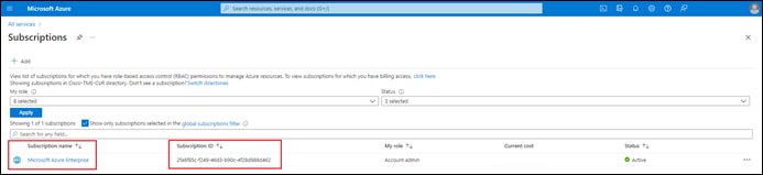
Step 4. Within the Subscriptions screen, locate your subscription and copy the Subscription ID.
A Subscription ID is a globally unique identifier (GUID) that identifies your subscription to utilize Azure services. It is one of the four IDs needed to provide Cisco Cloud onRamp for Multi-Cloud the information to programmatically access your Azure subscription via API calls. When you have completed this step, you will have the first of the four credentials needed to configure a cloud account within Cisco Cloud onRamp for Multi-Cloud:
● Subscription ID
Step 5. Click on your Subscription name to bring up the details regarding your subscription.
Step 6. From the navigation panel on the left side of the screen, select Access Control (IAM).
This will bring up the Access Control (IAM) screen for your subscription.
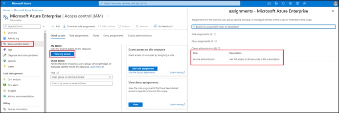
Step 7. Click on View my access to bring up the side panel which shows your access.
Classic administrators are needed if you are still using Azure classic deployments. Otherwise, role assignments are generally recommended. The following table shows the four roles under the General category within Azure RBAC:
Table 26. General Roles within Azure RBAC
| Role |
Description |
| Owner |
Grants full access to manage all resources, including the ability to assign roles in Azure RBAC . |
| Contributor |
Grants full access to manage all resources but does not allow you to assign roles in Azure RBAC, manage assignments in Azure Blueprints, or share image galleries. |
| Reader |
View all resources but does not allow you to make any changes. |
| User Access Administrator |
Allows you to manage user access to Azure resources. |
For details on Azure roles refer to the Azure roles and privileges guide. You will need Microsoft.Authorization/*/Write access to assign a role to an Azure AD application. This action is associated only with the Owner or User Access Administrator roles. Classic administrators (shown in the figure above) have the equivalent of the Owner role. If your account is assigned the Contributor or Reader roles, you do not have adequate permission. You will receive an error when attempting to assign the service principal a role. Ask your subscription administrator to add you to User Access Administrator role.
The next process discusses how you grant the registered application the necessary permissions to access and/or create resources within your Azure subscription.
Process: Register an Application with Azure Active Directory (AD)
Cisco Cloud onRamp for Multi-Cloud running within vManage uses Azure REST-based APIs to access and/or create resources such as a vWAN and vHub if necessary, instantiate a pair of Cisco Catalyst 8000v routers functioning as NVAs within the vHub, tag host vNets, and establish peering connections between the vHub and host vNets, among other things. To accomplish this, Cisco Cloud onRamp for Multi-Cloud is represented as an application registered within Azure Active Directory (AD)
Azure AD is Microsoft’s cloud-based centralized identity provider. When an application is registered with Azure AD, a globally unique application object is created, providing an identity configuration for the application. This allows the application to delegate Identity and Access Management (IAM) functions to Azure AD, rather than having the application sign in users itself. The application object is used as a template to create one or more service principal objects. A service principal must be created in each tenant where the application is used, enabling it to establish an identity for sign-in and/or access to resources being secured by the tenant. Registering an application within the Azure portal creates both an application object as well as a service principal object.
When registered, the application is provided with a unique identifier – the Client ID (also known as the Application ID). Confidential client applications also require the addition of secrets (secret keys) or certificates which are also shared with the Microsoft Identity platform. In order to create a cloud account within Cisco Cloud onRamp for Multi-Cloud you will need both the Client / Application ID and a Secret Key.
Procedure 1. Register an Application with Azure AD and Create a Service Principal
The steps for registering an application with Azure AD and creating a service principal via the Azure portal are as follows:
Step 1. Log into the Microsoft Azure portal.
Step 2. From the Azure portal home screen click on more services à to display the All Services screen.
Step 3. From the All Services screen, click on App registrations under the Other category.
This will bring up the App registrations screen.
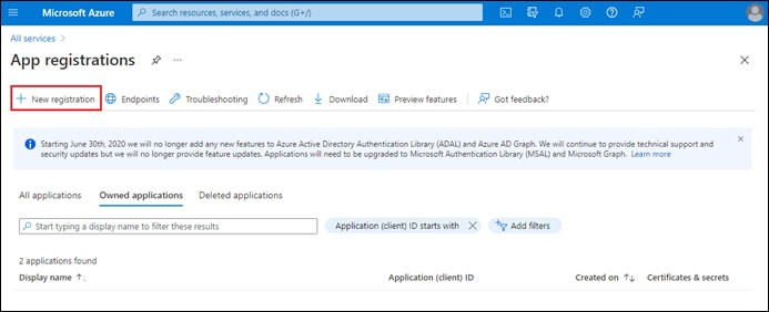
Step 4. Click New registration to bring up the Register an application screen.
Step 5. In the Name field, enter a descriptive name.
For this guide the name of the application is CloudOnRamp.
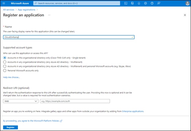
For this guide is a single tenant application is configured. The rest of the tabs can be left as default.
Step 6. After setting the values, select Register to create the application ID object and service principal object within Azure AD.
Procedure 2. Create a Secret Key for the Cisco Cloud onRamp for Multi-Cloud Application
Since Cisco Cloud onRamp for Multi-Cloud is considered a confidential client application, you must add a Secret Key for the application to use when authenticating itself to Azure AD.
Step 1. From the App registrations screen, click on the application that was registered in the previous procedure.
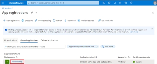
Step 2. From the navigation panel on the left side of the screen, select the Overview tab.
Step 3. Within the Overview screen you can see the Application (client) ID, and the Directory (tenant) ID. Copy both of these down for use when you create the cloud account within Cisco Cloud onRamp for Multi-Cloud with Azure.
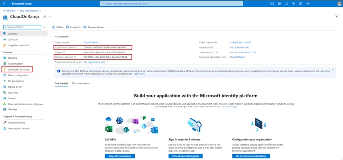
Step 4. From the navigation panel on the left side of the screen, under the Manage section, select Certificates & secrets.
Step 5. In the Certificates & secrets screen, click on + New client secret.
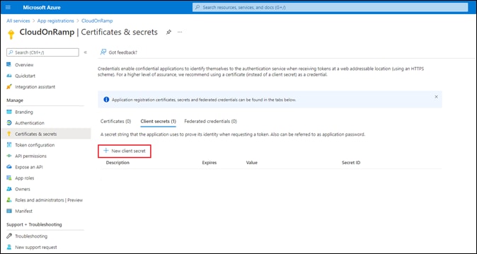
Step 6. In the Add a client secret side screen which appears, add a Description and from the drop-down menu adjacent to Expires, select a time period when the secret will expire.
Step 7. Click Add to add the client secret.
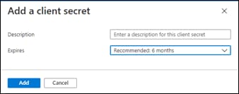
Once you have added the client secret, you should see it in the Certificates & secrets screen.
Step 8. Within the Certificates & secrets screen, click on the copy button [] to copy the Value of the secret (not the Secret ID). This value is used as the Secret Key when you configure a new cloud account within Cisco Cloud onRamp for Multi-Cloud with Azure.
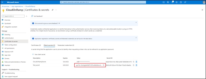
When you have completed this step, you will have all four of the credentials needed to configure a cloud account within Cisco Cloud onRamp for Multi-Cloud:
● Subscription ID
● Tenant ID (also known as the Directory ID)
● Client ID (also known as the Application ID)
● Secret Key (the Value of the Secret ID)
Once you have registered the application, you must also grant the application the necessary permissions within Azure Active Directory (AD) to access and/or create resources within your Azure subscription. This is done through the assignment of roles to the service principal representing the application.
Process: Assign a Role to the Application
Cisco Cloud onRamp for Multi-Cloud running within vManage uses the credentials discussed in the previous process to access Azure via REST-based APIs. Azure Role-Based Access Control (RBAC) is the authorization system you use to manage access to Azure resources. To grant Cisco Cloud onRamp for Multi-Cloud access to the necessary resources, you must assign a role to the service principal representing the application registered in the previous process.
Table 26 in a previous process shows the four roles under the General category within Azure RBAC. Each of the roles has a list of specific permissions which can be viewed within Azure. The Reader and User Access Administrator roles do not have sufficient permissions to allow Cisco Cloud onRamp for Multi-Cloud to add the necessary resources for the Cloud Gateway within your Azure subscription. Both the Owner and Contributor roles have sufficient permissions. The Contributor role is the role selected for this guide.
The following are the steps to assign the Contributor role to the application registered in the previous process.
Step 1. Log into the Microsoft Azure portal.
Step 2. From the Azure portal home screen click on more services à to display the All Services screen.
Step 3. Within the All Services screen, click on Subscriptions located within the General category.
Step 4. Click on your Subscription name to bring up the details regarding your subscription.
Step 5. From the navigation panel on the left side of the screen, select Access Control (IAM).
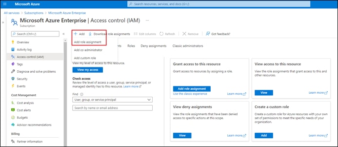
Step 6. From the Access control (IAM) screen, click + Add and from the drop-down menu select Add role assignment.
This will bring up the first screen in the Add role assignment workflow.
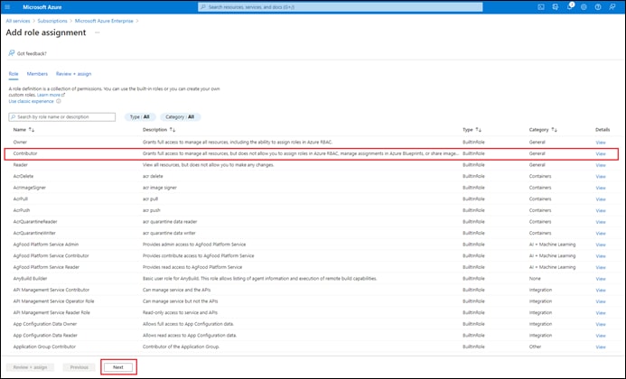
Step 7. Select the Contributor role and click Next to bring up the second screen in the Add role assignment workflow.
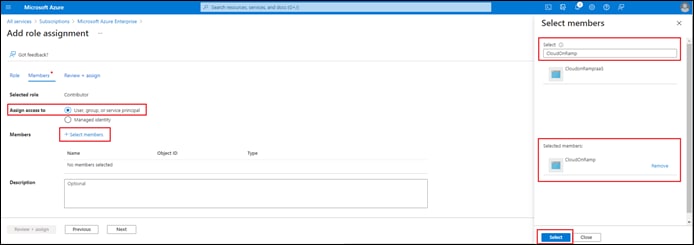
Step 8. Make sure the User, group, or service principal radio button is selected adjacent to Assign access to.
Step 9. Click on + Select members to bring up the Select members side panel.
Step 10. In the open text field under Select, type in the name of the application that you registered in the previous process.
You should see the application appear as one of the choices for you to select. For this guide, the application name is CloudOnRamp.
Step 11. Click on the application name to move it under the Selected members list.
Step 12. Click the Select button to select the application to have the role of Contributor.
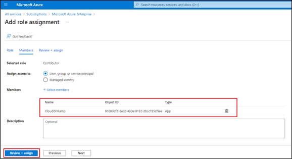
You should see the application / service principal added in the previous process now included in the list of members to be added to the role of Contributor.
Step 13. Click on Review + assign to move to the next screen, and then click on Review + assign again, to assign the Contributor role to the application / service principal.
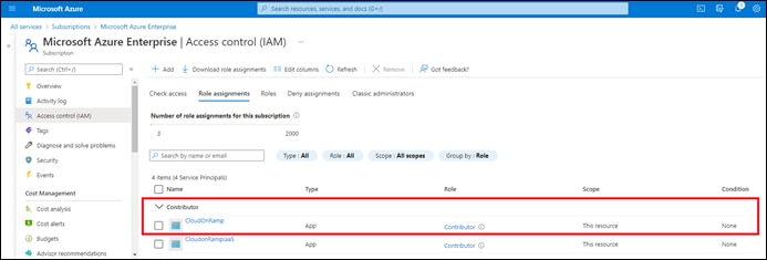
If you return to the Access Control (IAM) screen and click on Role Assignments, you should see the application /service principal now, with the role of Contributor.
Appendix F: Integration with a Service vNet Hosting a Load-Balancer and Firewalls
Rather than mapping host vNets directly to the vHub, as discussed earlier in the Deploy - Cisco Cloud onRamp for Multi-Cloud with Azure section of this document, an alternative design is to map a service/transit vNet to the vHub. For the purposes of this document the service/transit vNet is referred to as the Service vNet. The Service vNet serves as a transit vNet between the vHub and the host vNets. The benefit of this design is that it allows for the insertion of a load balancer and firewalls within the Service vNet, between the vHub and the host vNets.
An example of this design is shown in the following figure.
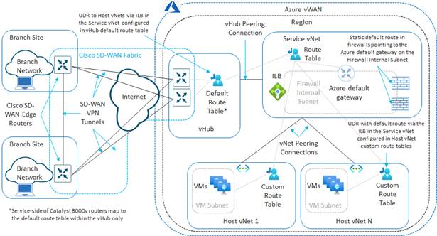
In this design, instead of peering individual host vNets to the vHub/Cloud Gateway, the Service vNet is peered to the Azure vHub/Cloud Gateway through the Cisco Cloud onRamp Intent Management workflow. Individual host vNets are manually peered to the Service vNet. The Service vNet includes an Azure Internal Load Balancer (ILB) which front-ends one or more 3rd party firewalls operating as Network Virtual Appliances (NVAs).
This design allows for traffic flows to-and-from the SD-WAN sites to the host vNets as well as east-west traffic flows between the host vNets to be routed through the load-balancer and firewalls. Note that since the primary focus of this guide is connectivity from the SD-WAN network into Azure, this guide does not discuss traffic to-and-from the Internet to the VMs within the host vNets, which would require an additional Azure Public/External Load Balancer.
In order to facilitate inbound traffic flows from the SD-WAN sites, Azure User Defined Routes (UDRs) are manually added to the default route table of the vHub, routing the traffic destined for the host vNets to the frontend IP address of the Azure ILB sitting within the Service vNet. In the example above, the Azure ILB is configured with a single frontend IP address. The backend pool (associated to the frontend IP address through a load-balancing rule) consists of the IP addresses of the firewalls. These interfaces sit on the Firewall Internal Subnet within the Services vNet. This causes inbound traffic from the SD-WAN network toward the VMs within the host vNets to be routed through the Azure ILB. The Azure ILB sends the traffic to one of the firewalls.
The firewalls must have either a default (0.0.0.0/0) route or specific routes to the address spaces of the host vNets and the SD-WAN network configured – pointing to the Azure default gateway which sits on the same subnet (the Firewall Internal Subnet in the figure above) as the firewalls. The manual peering of the host vNets to the Service vNet results in the host vNets learning about the IP address space of the Service vNet, and vice-versa. Therefore, traffic sent from the firewalls to the Azure default gateway of the Firewall Internal Subnet, can be routed by Azure to the VMs within the host vNets.
An example of traffic flows initiated from hosts within the SD-WAN network to the VMs within the host vNets is shown in the following figure.
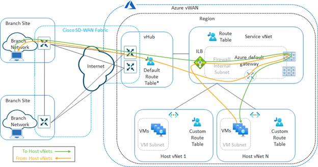
Because firewalls are usually stateful, return traffic from the host vNet VMs often needs to be routed back to the same firewall that initially allowed the traffic through (unless state is shared between firewalls). Azure standard ILBs maintain session affinity. This can be used to guarantee that the return traffic of a flow which was initially sent through the Azure ILB will be sent by the Azure ILB back to the same firewall. All that is needed is to route the return traffic from the host vNet VMs back to the Azure ILB within the Service vNet.
In the design shown in the figure above, an Azure custom route table is created for the host vNets. Within the custom route table, a default (0.0.0.0/0) route is configured, pointing to the frontend IP address of the Azure ILB. The host vNet knows how to reach the front-end IP address of the Azure ILB due to the peering with the Service vNet. Therefore, return traffic is sent back to the Azure ILB within the Service vNet.
Once the firewall has processed the return traffic, it is sent to the Azure default gateway of the Firewall Internal Subnet, based on the static default (0.0.0.0/0) route within the firewall (or specific routes to the address spaces of the host vNets and the SD-WAN network if configured). The peering of the Service vNet with the vHub/Cloud Gateway within the Intent Management workflow of Cisco Cloud onRamp for Multi-Cloud results in the propagation of routes between the vHub and the Service vNet. This allows the Service vNet to learn about the IP address space of the SD-WAN network, and vice-versa.
Since the vHub is BGP peered with the Cisco Catalyst 8000v routers functioning as NVAs, routes learned from the SD-WAN network via OMP are re-distributed into the vHub, which are then propagated to the Service vNet. This allows Azure to route the return traffic back to the Cisco Catalyst 8000v routers within the vHub and through the SD-WAN fabric to the branch and/or campus sites. Likewise, routes learned from the vHub (including the User Defined Routes (UDRs) to the host vNets) are re-distributed from BGP into OMP at the Catalyst 8000v routers. This allows the SD-WAN remote sites to learn about the IP address space of the host vNets, in order to initiate the traffic flows toward Azure in the first place.
Note that the same routing applies to traffic flows initiated from the VMs within the host vNets toward the SD-WAN network. It is up to the network administrator to configure the firewall with the necessary security policy in order to determine what flows are allowed to be initiated inbound from the SD-WAN network to the host vNet VMs, and what flows (if any) are allowed to be initiated outbound from the host vNet VMs to the SD-WAN network.
An example of east-west traffic flows initiated from VMs within one host vNet to VMs on another host vNet is shown in the following figure.
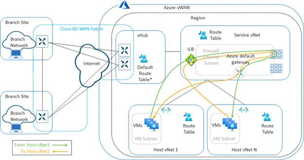
For east-west traffic flows between the host vNets, the default (0.0.0.0/0) route configured within the custom route table assigned to the host vNets causes all traffic from the initiating host vNet to be sent to the Azure ILB within the Service vNet. The Azure ILB routes the traffic to one of the firewalls. Once the firewall has processed the flow based upon its security policy, the traffic is sent to the Azure default gateway of the Firewall Internal Subnet, based on the static default (0.0.0.0/0) route within the firewall (or specific routes to the address spaces of the host vNets and the SD-WAN network if configured). The peering of the host vNets with the Service vNet allows Azure to route the traffic to the required destination host vNet.
The return traffic is sent from the destination host vNet back to the Azure ILB within the Service vNet. Since Azure standard ILBs maintain session affinity, the return traffic flow is sent to the same firewall through which the flow initially passed. The firewall in turn sends the return traffic to the Azure default gateway of the Firewall Internal Subnet, which is then routed by Azure to the initiating host vNet. Hence, all east-west traffic between host vNets passes through the Azure ILB and firewalls within the Service vNet.
| Technical Note |
| There are multiple ways of configuring load-balancers with firewalls, depending upon the requirements of the deployment. The design presented within this guide shows single interface firewalls. Traffic is routed into and out the same interface of the firewall, with session affinity of the Azure standard ILB used to guarantee return traffic is sent through the same firewall. Other designs can be implemented depending upon the requirements of the deployment. For example, if the requirement is only for traffic to and from the SD-WAN network to the host vNets, with the traffic flows initiated from the SD-WAN network, then a design using firewalls with two interfaces (“inside” and “outside”) and source NAT may be acceptable. In this type of design, source NAT is implemented within the firewalls as the traffic exits the firewall through the “inside” interfaces toward the VMs within the host vNets. From the perspective of the VMs, the inbound traffic originates from the “inside” addresses of the firewalls. This guarantees that the return traffic from the VMs will be sent back to the same firewall from which the flow originated. Note however, that this design may not necessarily accommodate east-west traffic between host vNets, or traffic initiated from the host vNets toward SD-WAN network. Alternatively, Azure now supports Route Servers, which allow direct BGP peering with NVAs functioning as firewalls, as well as other constructs such as Gateway Load Balancers. These may provide alternative way of routing traffic through firewalls and are not covered within this document. |
The following procedures are intended to show how to provide network connectivity between an existing Service vNet, which contains an Azure Internal Load Balancer (ILB) and firewalls (based upon the design shown in the figures above), and the SD-WAN network – through the Cloud Gateway which is instantiated via Cisco Cloud onRamp for Multi-Cloud with Azure. As such, this guide will not discuss how to create a Service vNet, how to instantiate an Azure ILB within that Service vNet, or how to instantiate 3rd party firewalls functioning as NVAs within the Service vNet. However, this guide will provide examples of how to configure the routing within these entities in order to provide the necessary connectivity from the SD-WAN routers within the vHub/Cloud Gateway to the VMs within the host vNets.
The following procedures assume the following:
● The Services vNet shown in the figures above has already been created within Azure.
● The Azure Internal Load Balancer (ILB) shown in the figures above has already been created within Azure.
● One or more 3rd party firewalls, functioning as NVAs within the Azure Service vNet have been instantiated within the Service vNet. For this guide, the firewalls are assumed to have only one interface.
● One or more host vNets shown in the figures above have already been created within Azure.
The procedures for creating a Cloud Gateway, discovering and tagging a vNet, and mapping the vNet to the Cloud gateway are identical to the Deploy a Cloud Gateway with Cisco Cloud onRamp for Multi-Cloud section of this guide – except that the Service vNet is mapped to the Cloud Gateway instead of the individual host vNets. These procedures will not be duplicated here. Please ensure you have instantiated the Cloud Gateway and mapped a service VPN to the tagged Service vNet within Cisco Cloud onRamp for Multi-Cloud with Azure before continuing.
The following are the procedures for configuring the design discussed within this guide:
● Peer the host vNets to the Service vNet within Azure.
● Add User Defined Routes (UDRs) for the host vNets, reachable via the frontend IP address of the Azure Internal Load Balancer (ILB) within the Service vNet, to the default route table of the Azure vHub with the Cloud Gateway.
● Add a custom route table to the VM subnets of the host vNets. Within the custom route table add a default route (0.0.0.0/0), pointing to the frontend IP address of the Azure Internal Load Balancer (ILB) within the Service vNet.
● Within the firewalls, ensure that there is at least a default (0.0.0.0/0) route pointing to the Azure default gateway of the subnet (Firewall Internal Subnet) upon which the firewall sits.
Procedure 1. Peer the Host vNets to the Service vNet within Azure
The following are the steps to peer the host vNets to the Service vNet within Azure.
Step 1. Log into the Microsoft Azure portal.
Step 2. From the Azure portal home screen click on more services à to display the All Services screen.
Step 3. Within the All Services screen, click on Virtual networks located within the Networking category.
This will bring up the Azure Virtual Network Screen.
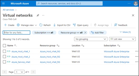
Your host vNets and the Service vNet should appear within the Virtual Networks Screen.
Step 4. Select the first host vNet which you wish to peer with the Service vNet.
This will bring up information on the specific host vNet which you chose.
Step 5. In the navigation panel on the left side of the screen which appears, click on Peerings.
If there are no peerings, the screen that appears will be blank.
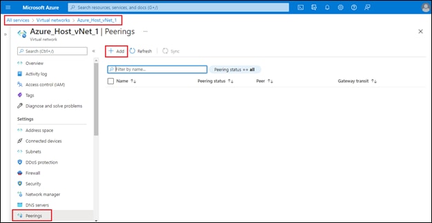
Step 6. Click on the + Add link to bring up the Add Peering screen to add a new vNet-to-vNet peering.
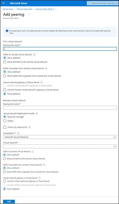
Step 7. Fill out the required information for the screen.
The following table discusses the settings for the peering within this deployment guide.
Table 27. Host vNet to Service vNet Peering Settings
| Parameter |
Setting |
| This virtual network – Peering link name |
Host_vNet_1_to_Service_vNet |
| This virtual network – Traffic to remote virtual network |
Allow (default) |
| This virtual network – Traffic forwarded from remote virtual network |
Allow (default) |
| This virtual network – Virtual network gateway or Route Server |
None (default) |
| Remote virtual network – Peering link name |
Service_vNet_to_Host_vNet_1 |
| Remote virtual network – Virtual network deployment model |
Resource manager |
| Remote virtual network – I know my resource ID |
Unchecked |
| Remote virtual network – Subscription |
<Choose subscription from the drop-down menu> |
| Remote virtual network – Virtual network |
Azure_Service_vNet |
| Remote virtual network – Traffic to remote virtual network |
Allow (default) |
| Remote network – Traffic forwarded from remote virtual network |
Allow (default) |
| This virtual network – Virtual network gateway or Route Server |
None (default) |
Note that the design discussed within this section has no Virtual Network Gateways (VNGs) or Route Servers defined within either the Service vNet or the host vNets. This allows for the selection of None for the radio button adjacent to Virtual network gateway or Route Server on both sides of the peering. When the radio-button selection for Virtual network gateway or Route Server is selected as None, routes learned via the peering will not be propagated to any Virtual Network Gateway (VPN or ExpressRoute) or Route Server. Likewise, any routes known by any Virtual Network Gateway (VNG) will not be propagated across the peering connection. The effect of setting both sides of the peering to None, is that the host vNet will only learn about the IP address space of the Service vNet, and the Service vNet will only know about the IP address space of the host vNet. The address space of the host vNet will not be propagated to the vHub. This requires the addition of User Defined Routes (UDRs) for the host vNets within the default route table of the vHub. This is discussed in the next procedure.
Step 8. When you have filled out the settings within the Add Peerings screen, click Add to add both sides of the peering connection.
After a few moments, the new peering should appear within the host vNet as shown below.
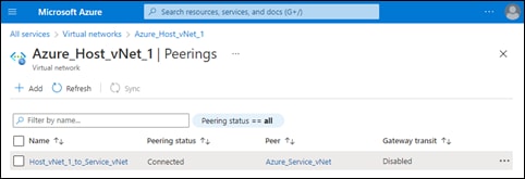
Step 9. Repeat Steps 1 – 8 for any other host vNets which need to be peered with the Service vNet – modifying the names of the peering connections as necessary within the Add Peerings Screen.
Procedure 2. Add User Defined Routes (UDRs) to the Host vNets in the Default Route Table of the vHub
The following are the steps for adding UDRs to the host vNets within the default route table of the vHub within Azure.
Step 1. Log into the Microsoft Azure portal.
Step 2. From the Azure portal home screen click on more services à to display the All Services screen.
Step 3. Within the All Services screen, click on Virtual WANs located within the Networking category.
This will bring up the Azure Virtual WANs Screen.
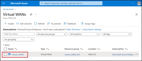
Step 4. Locate the and select the vWAN in which you instantiated the Cloud Gateway.
This will bring up details regarding the specific vWAN.
Step 5. Make sure Overview is selected in the navigation panel on the left side of the screen.
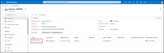
Step 6. Within the vWAN, locate and select the vHub in which you instantiated the Cloud Gateway.
This will bring up details regarding the specific vHub.
Step 7. Make sure Overview is selected in the navigation panel on the left side of the screen.
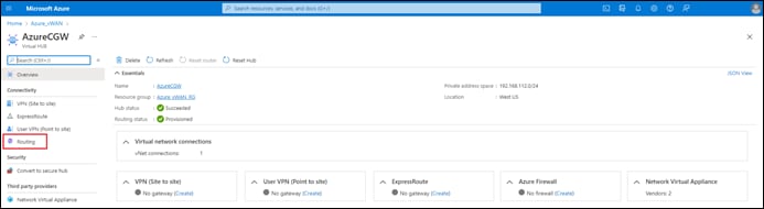
Step 8. From the navigation panel on the left side of the screen under the Connectivity section, select Routing.
This will bring up the Routing screen for the vHub.
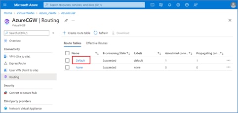
Step 9. Select the Default route table.
This will bring up the Edit route table workflow for the Default route table. The Edit route table workflow consists of four screens: Basics, Labels, Associations, and Propagations – beginning with the Basics screen.
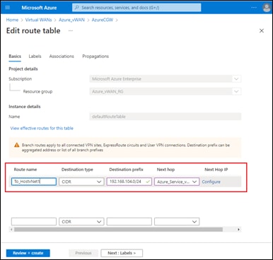
Step 10. In the open text box under Route name, type in a name for the route to the first host vNet.
Step 11. From the drop-down menu under Destination type, select CIDR. This is the default selection.
Step 12. In the open text box under Destination prefix, type in the IP destination prefix for the first host vNet.
Step 13. From the drop-down menu under Next hop, select the Service vNet which was mapped to the vHub within the Intent Management workflow of Cisco Cloud onRamp for Multi-Cloud.
When you select the Next hop from the drop-down menu, a link named Configure will appear under Next Hop IP.
Step 14. Click on the Configure link under Next Hop IP to configure the IP address of the next hop to reach the destination prefix.
The following screen will appear.
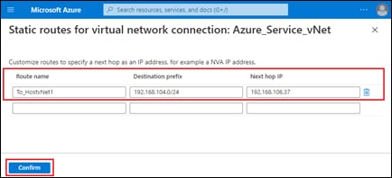
Step 15. In the open text box under Next hop IP, type in the frontend IP address of the Azure Internal Load Balancer (ILB) within the Service vNet.
This will send all traffic destined for the host vNet to the Azure ILB that front-ends the firewalls within the Service vNet.
Step 16. Add additional UDRs to other host vNets that are peered to the Service vNet, as required, directly within the screen.
Step 17. When you are done adding UDRs, click Confirm to return to the Edit route table - Basics screen.
Step 18. Click Next: Labels > to advance to the next screen in the workflow, the Edit route table – Labels screen.
Step 19. Since there is no need for labels within this guide, click Next: Associations > to advance to the next screen in the workflow, the Edit route tables – Associations screen.
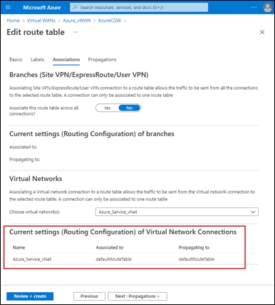
You should see that the Service vNet (named Azure_Service_vNet in this guide) is both Associated to and Propagating to the default route table (named defaultRouteTable). Association and propagation of routes between the Service vNet and the default route table of the vHub was done programmatically within the Intent Management workflow of Cisco Cloud onRamp for Multi-Cloud when the Service vNet was mapped to the Cloud Gateway.
Step 20. Click Next: Propagations > to advance to the next screen in the workflow, the Edit route tables – Propagations screen.
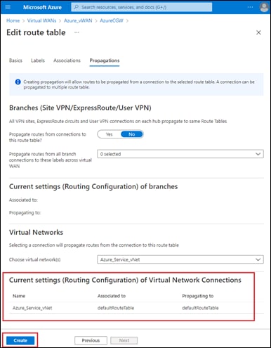
As with the Edit route table – Associations screen, you should see that the Service vNet (named Azure_Service_vNet in this guide) is both Associated to and Propagating to the default route table (named defaultRouteTable).
Step 21. Since there is no need to make any changes to the Edit route table – Propagations screen within the workflow, click Create to complete the addition of the UDRs to the default route table.
This should take you back to the Routing screen for the vHub. The UDRs should now appear if you click on the Default route table to advance to the Edit route table – Basics screen.
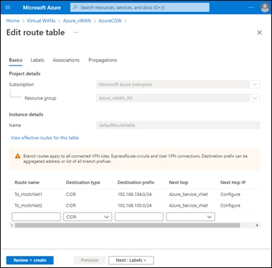
The following table summarizes the UDRs added to the default route table of the Cloud Gateway for this guide.
Table 28. User Defined Routes (UDRs) to Host vNets
| Route Name |
Destination Type |
Destination Prefix |
Next Hop |
Next Hop IP |
| To_HostvNet1 |
CIDR |
192.168.104.0/24 |
Azure_Service_vNet |
192.168.106.37 |
| To_HostvNet2 |
CIDR |
192.168.105.0/24 |
Azure_Service_vNet |
192.168.106.37 |
| Technical Note |
| If you edit the routes within the default route table of the vHub to manually add static routes to host vNets which are available via the front-end IP address of the Azure Internal Load Balancer (ILB), you must first manually remove those static routes if you ever decide to delete the Cloud Gateway within Cloud onRamp for Multi-Cloud. Otherwise, Cloud onRamp for Multi-Cloud may generate an error when attempting to delete the Cloud Gateway. |
Procedure 3. Add a Custom Route Table with Default Route to the Host vNets
The following are the steps for configuring a custom route table within Azure, adding a default route to the route table, and then associating the custom route table to the subnets which contain VMs within the host vNets which are peered to the Service vNet. The default route points to the front-end IP address of the Azure Internal Load-Balancer (ILB) within the Service vNet. The default route is used to ensure that traffic initiated by the VMs within the host vNets (for example east-west traffic between host vNets) is sent through the firewalls within the Service vNet.
Step 1. Log into the Microsoft Azure portal.
Step 2. From the Azure portal home screen click on more services à to display the All Services screen.
Step 3. Within the All Services screen, click on Route tables located within the Networking category.
This will bring up the Azure Route tables screen.
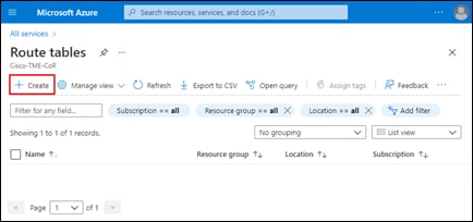
Step 4. Click + Create to bring up the Create Route table workflow – Basics screen.
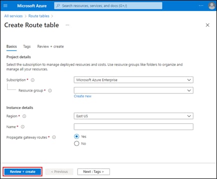
The Create Route table workflow consists of three screens: Basics, Tags, and Review + create.
Step 5. Fill in the necessary information within the Create Route Table – Basics screen.
The following table summarizes the custom route table created for this guide.
Table 29. Custom Route Table for Host vNets
| Setting |
Description / Explanation |
Deployment Guide Value |
| Subscription |
Select your subscription from the drop-down menu. |
Microsoft Azure Enterprise |
| Resource Group |
Select the resource group in which the route table will be created from the drop-down menu. Since the route table will be associated to the subnets within the host vNets, it was created in the same Azure resource group as the host vNets for this guide. |
Azure_Host_vNet_RG |
| Region |
Select the Azure region in which the route table will be created from the drop-down menu. Since the host vNets to which the route table will be associated is in the West US region, the route table is created in the West US region also. |
West US |
| Name |
Fill in the name of the route table in the open text area adjacent to Name. |
Host_vNets_to_ILB_RT |
| Propagate gateway routes |
Select the radio button setting to determine if gateway routes are propagated. Set to No for this guide since a default route pointing to the front-end IP address of the Azure ILB within the Service vNet will be added to the route table. |
No |
Step 6. Skip the Tags workflow step by clicking on Review + create to move to the last step in the workflow.
Step 7. When the Create Route table – Review + create screen comes up, click Create to create the custom route table.
When the deployment is complete, navigate back to the Route Tables screen. The new route table should appear.
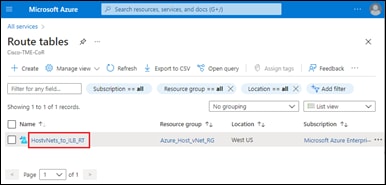
Step 8. Click on the new route table.
This will bring up the overview screen for the route table.
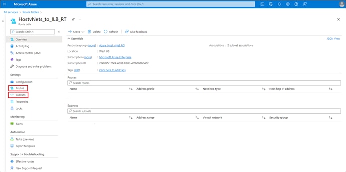
Step 9. In the navigation panel on the left side of the screen, click on Routes under the Settings screen.
Step 10. In the screen which appears, click + Add.
This will bring up the Add Route screen.
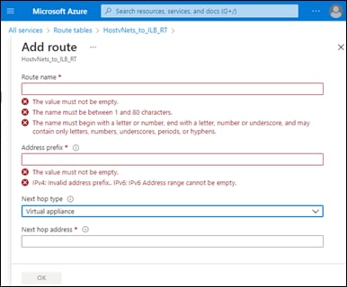
Step 11. In the empty text field under Route name, type in a name for the route.
Step 12. In the empty text field under Address prefix, type in a default route 0.0.0.0/0.
Step 13. From the drop-down menu under Next hop type, select Virtual appliance.
This will cause the Next hop address field to appear.
Step 14. In the empty text field under Next hop address, type in the front-end IP (FIP) address of the Azure Internal Load Balancer (ILB) within the Service vNet.
The following table summarizes the UDR added to the custom route table for this guide.
Table 30. User Defined Route (UDR) for Host vNet subnets
| Route Name |
Address Prefix |
Next Hop Type |
Next hop address |
| To_ILB |
0.0.0.0/0 |
Virtual Appliance |
192.168.106.37 |
Step 15. When you have filled in all of the required fields, click OK to add the route to the custom route table.
After a few moments, you should see the new User Defined Route (UDR) added to the custom route table.
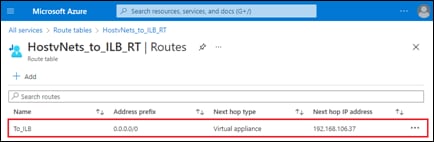
Step 16. In the navigation panel on the left side of the screen, click on Subnets under the Settings screen.
Step 17. In the screen which appears, click + Associate.
This will bring up the Associate subnet side-panel.
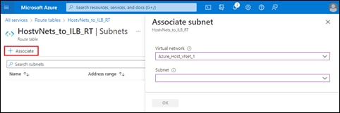
Step 18. From the drop-down menu under Virtual network, select the first host vNet peered with the Service VPN.
Step 19. From the drop-down menu under Subnet, select the subnet which contains the VMs from the host vNet.
Step 20. Click OK to associate the subnet with the custom route table.
Step 21. Repeat Steps 17 – 20 to associate any additional subnets within the same host vNet, or different host vNets to the custom route table.
When you have associated the subnets, the Subnets screen should appear similar to the following.
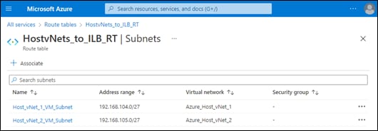
The following table summarizes the subnet associations for the custom route table for this guide.
Table 31. Subnet Associations to Custom Route Table
| Virtual Network |
Subnet |
Address Range |
| Azure_Host_vNet_1 |
Azure_vNet_1_Subnet |
192.168.104.0/27 |
| Azure_Host_vNet_2 |
Azure_vNet_2_Subnet |
192.168.105.0/27 |
Step 22. Navigate back to the Overview screen of the custom route table to see both the default route and the subnet associations.
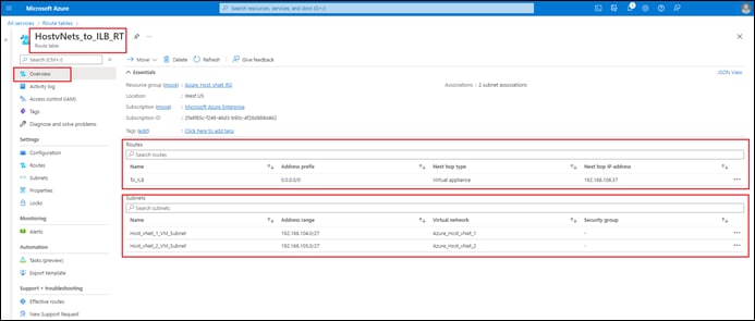
You can also verify the default route has been added to a subnet by looking at the effective routes for the network interface of one of the Azure VMs which sit on that subnet. The following figure shows the effective routes for the network interface of a VM sitting on the Host_vNet_1_VM_Subnet subnet within the Azure_Host_vNet_1 vNet.
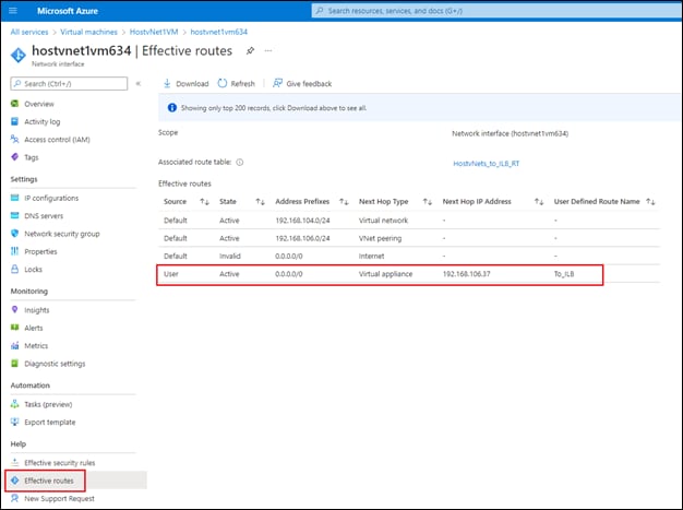
Procedure 4. Ensure the Firewalls Have at Least a Static Default (0.0.0.0/0) Route to the Azure Default Gateway
The design presented within this section of the guide assumes the firewalls operating as 3rd party NVAs within the Service vNet do not have any BGP peerings by which they can learn routes. Also, the firewalls in this design only have a single interface. Because of this, at a minimum, the firewalls need to have a static default (0.0.0.0/0) route pointing to the Azure default gateway of the subnet upon which the firewalls sit.
The procedure discussed here is presented as an example for reference. For this guide the firewalls were simulated using two Azure VMs running Ubuntu 18.04 LTS. In production environment, it is recommended that you run hardened 3rd party firewall/security network virtual appliances (NVAs), such as Cisco Firepower Threat Defense Virtual (FTDv). The following URL provides a guide for implementing Cisco Firepower Threat Defense Virtual (FTDv) firewalls within Azure:
The route table of a Linux machine can be checked with the route command. The following is the output from one of the simulated firewalls.
user@HostFirewall1:~$ route
Kernel IP routing table
Destination Gateway Genmask Flags Metric Ref Use Iface
default _gateway 0.0.0.0 UG 100 0 0 eth0
168.63.129.16 _gateway 255.255.255.255 UGH 100 0 0 eth0
169.254.169.254 _gateway 255.255.255.255 UGH 100 0 0 eth0
192.168.106.32 0.0.0.0 255.255.255.240 U 0 0 0 eth0
If the IP address of the firewall was configured via DHCP within Azure, then the default route pointing to _gateway should appear. The Azure default gateway is always the first IP address of the subnet within which the network interface of the device is associated. For reference, a non-persistent static default route can be added with the following command.
sudo ip route add 0.0.0.0/0 via 192.168.106.33 dev eth0
In the command above, the subnet upon which the eth0 network interface of the firewall is associated has an IP address space of 192.168.106.32/27. Hence the first IP address is 192.168.106.33. This is the Azure default gateway of the subnet.
Instead of a default route, more specific routes to the host vNets and IP address space of the SD-WAN network could also be configured. An example is as follows for the host vNet with IP address space of 192.168.102.0/24.
sudo ip route add 192.168.104.0/24 via 192.168.106.33 dev eth0
Remember, that these routes are non-persistent, meaning they will disappear if the Linux machine is rebooted, and are presented here purely for testing / reference. Also, if testing with Ubuntu 18.04 LTS machines, don’t forget to enable IP forwarding on both the Linux machine itself and on the Azure network interface of the VM; and disable ICMP redirects.
ASN Autonomous system number
BGP Border Gateway Protocol
eBGP External Border Gateway Protocol
GRE Generic Route Encapsulation
Host vNet Azure vNet containing VMs running your applications
IETF Internet Engineering Task Force
IaaS Infrastructure as a Service
NVA Network Virtual Appliance
STUN Session Traversal Utilities for NAT
vHub Azure Virtual Hub
VNG Azure Virtual Network Gateway (VPN or ExpressRoute)
vNet Azure Virtual Private Network
VPN Virtual Private Network
vWAN Azure Virtual WAN
WAN Wide Area Network
For comments and suggestions about this guide and related guides, join the discussion on Cisco Community at https://cs.co/en-cvds.