Security Policy Design Guide for Cisco IOS-XE SD-WAN Devices
Available Languages
Bias-Free Language
The documentation set for this product strives to use bias-free language. For the purposes of this documentation set, bias-free is defined as language that does not imply discrimination based on age, disability, gender, racial identity, ethnic identity, sexual orientation, socioeconomic status, and intersectionality. Exceptions may be present in the documentation due to language that is hardcoded in the user interfaces of the product software, language used based on RFP documentation, or language that is used by a referenced third-party product. Learn more about how Cisco is using Inclusive Language.
- US/Canada 800-553-2447
- Worldwide Support Phone Numbers
- All Tools
 Feedback
 Feedback
A security policy defines how an organization protects its information technology assets from external and internal attackers and is a critical element of today’s networking infrastructure. Security engineers and network administrators often have to navigate between maintaining maximum security while also keeping infrastructure costs down. The most common method is by installing security appliances within each remote site or backhauling traffic to a Data Center/ HQ to be inspected. These designs are either expensive to implement or can lead to situations of saturated links, decreased bandwidth and increased latency.
A solution to overcome the above-mentioned drawbacks is to make your network Cisco SD-WAN ready. Within the Cisco SD-WAN network, you can protect your remote sites with essential security capabilities embedded natively in the Cisco SD-WAN solution, without the need to install any additional security appliance(s). Using the cloud-based single-pane of management, security capabilities such as Enterprise Firewall with Application Awareness, Intrusion Prevention Systems with Cisco Talos Signatures (IPS/IDS), URL Filtering (URLF), Advanced Malware Protection (AMP) and DNS/Web-layer Security with Umbrella Integration can be configured within a given remote site’s IOS-XE SD-WAN WAN Edge device.
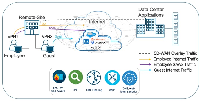
The security features offered at the remote site include:
Table 1. List of Security Features
| Security Feature Set |
Description |
| Enterprise Firewall with Application Awareness |
A stateful firewall with NBAR2 application detection engine to provide application visibility and granular control, capable of detecting 1000s of applications. |
| Intrusion Prevention/ Detection System (IPS/IDS) |
Threat prevention technology that examines network traffic flows to detect and prevent vulnerability exploits (signature violations). Note, the IPS feature works in the network intrusion detection and prevention mode. In Intrusion Detection System (IDS) mode, Snort inspects the traffic and reports alerts, but does not take any action to prevent attacks. In Intrusion Prevention System (IPS) mode, in addition to Intrusion detection, actions are taken to prevent attacks. Note, the system is backed by Cisco Talos signatures and are updated automatically. The feature is deployed using a security virtual image or a Unified Threat Defense (UTD) file available for download on software.cisco.com. |
| URL Filtering (URLF) |
Enforces acceptable use controls to block or allow URLs based on 82 different categories or a web reputation score. The URL Filtering system is also deployed using a security virtual image or UTD file. |
| Advanced Malware Protection (AMP)
|
AMP uses global threat intelligence, advanced sandboxing, and real-time malware blocking to prevent breaches. It also continuously analyzes file activity across your extended network, so you can quickly detect, contain, and remove advanced malware. The Advanced Malware Protection (AMP) system is also deployed using a security virtual image. |
| DNS/ Web-layer Security |
A leading security efficacy for malware, phishing, and unacceptable requests by blocking based on DNS requests. These DNS requests are redirected from their intended DNS server to Cisco Umbrella or to a custom DNS Server. Within Cisco Umbrella the request is processed based on your defined policy and responded with either the correct IP address of the service or any IP address redirecting the client to a block page. |
The Cisco SD-WAN security capabilities help customers achieve segmentation, threat protection, content filtering, PCI compliance and secure local internet exit at the remote site without the need of installing any additional security appliances. With Cisco Umbrella DNS/Web-security layer, you can get an additional layer of protection for all branch users from malware, botnets, phishing, and targeted online attacks.
This design guide focuses on the design components, considerations, working and best practices of each of the security features listed in Table 1 for IOS-XE SD-WAN WAN Edge devices. However, the document is not meant to exhaustively cover all options.
The guide is a companion guide to the associated prescriptive deployment guides for SD-WAN, which provide details on deploying the intent-based SD-WAN security use cases and is based on Catalyst SD-WAN Manager version 19.2.1 and below, WAN Edge device 16.12.1e and below.
Note, this document assumes that the control components are already designed, deployed and integrated into Catalyst SD-WAN Manager, the WAN Edge devices are deployed and the SD-WAN overlay network is successfully established. Local Internet exit within each remote site is already configured and verified.
Refer to the Cisco SD-WAN Design Guide for background information and the Cisco SDWAN End-to-End Deployment Guide for information on deploying device templates to establish a Cisco SD-WAN overlay network. For the design and deployment of local Internet exit within a remote site refer to the Cisco SD-WAN Direct Internet Access Design and Deployment Guide. For details regarding the required licenses to deploy the Cisco SD-WAN security feature set, refer to the Cisco DNA Software for SD-WAN and Routing .
Cisco SD-WAN Intent-Based Use Cases
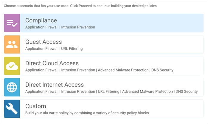
Based on common customer deployment scenarios, predefined workflows are added into Catalyst SD-WAN Manager to facilitate ease of deployment for the following use cases.
● Compliance use case caters to any organization that services customers, accepts credit card payment to be PCI compliant. In this use case, in addition to the data being encrypted and sent over an IPsec tunnel, all packets are subjected to a stateful firewall and an IPS solution.
● Guest access use case caters to companies wherein guests bring in BYOD devices and connect to an open or password protected Internet connection. To avoid any litigation, companies are liable to inspect and provide a good content filtering solution.
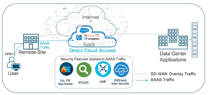
● Direct Cloud Access (DCA) use case caters to customers who need to route some SaaS application traffic for optimal performance via branch local Internet exit and route the rest of the Internet traffic via the HQ or Data Center. The cloud traffic is inspected for malware, along with content filtering.
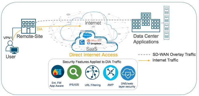
● Direct Internet Access (DIA) use case caters to organizations wherein all or some of the Internet traffic from a remote site exits via the local internet exit and is inspected for malware, along with content filtering and more.
Predefined workflows for each of the use cases are explained in Figure 2. You can also build your own custom security policy based on your use case by combining a custom variety of security features.
All the intent-based use cases are explained in detail in the upcoming sections.
Out of the four intent-based use cases available, one of the predominant use cases for enterprise customers is Compliance.
Within this use case, the primary requirement is to protect sensitive data, such as card holder or patient information, against data breaches. This makes it necessary to inspect traffic before it is tunneled across to the data center. In the Cisco SD-WAN solution, although data plane traffic is encrypted using SHA-256 and sent over a VPN tunnel, for compliance, all packets need to be subjected to a stateful firewall and an IPS solution.
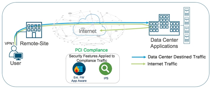
The Cisco SD-WAN features leveraged within this use case include:
● IPsec encrypted tunnel from branch to datacenter.
● Secure Segmentation via VPN/Zone to segment user traffic into zones and VPN/VRF.
● Enterprise Firewall with Application Awareness and IPS/IDS to maintain a PCI compliant network.
Table 2. Cisco SD-WAN Features to Enable PCI-Compliance
| Security Pillar |
SD-WAN Security Feature |
| Transport Security |
IPsec VPN |
| Segmentation |
VPN and FW Zone |
| Perimeter Control |
Enterprise Firewall with Application Awareness |
| Attack Prevention |
IPS/IDS |
Refer to this Prescriptive Deployment Guide - Cisco SD-WAN: Enabling Firewall and IPS for Compliance for the configuration and troubleshooting steps associated with the security features in this use case.
Use Case #2 - Secure Guest Access
Within the guest access use case, the primary requirement is to allow guest users to access Internet directly from the remote site, to offload Internet traffic from premium WAN connections and to improve application experience.
The second requirement is to secure the guest Internet traffic and branch network, by enabling advanced security features such as Enterprise Firewall with Application Awareness to inspect and limit traffic, and URL Filtering (URLF) for content filtering either directly on the WAN Edge router, or by routing Internet traffic through a cloud security provider.
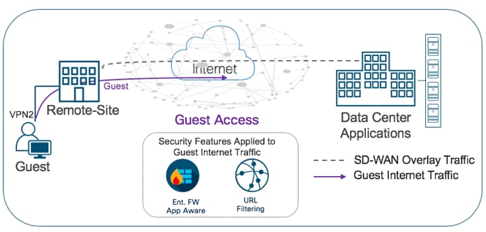
The Cisco SD-WAN features leveraged within this use case include:
● Secure Segmentation via VPN/Zone to segment guest traffic into zones and VPN/ VRF.
● NAT DIA route for local Internet exit of segmented guest Internet traffic. Optionally, you can also use centralized data policy to redirect some or all guest Internet traffic.
● Enterprise Firewall with Application Awareness and URL Filtering to maintain a secure guest access network.
Table 3. Cisco SD-WAN Features to Enable Secure Guest Access
| Security Pillar |
SD-WAN Security Feature |
| Segmentation |
VPN and Zone |
| Local Internet Exit |
Centralized Data Policy/ NAT DIA Route |
| Perimeter Control |
Enterprise Firewall with Application Awareness |
| Liability Protection |
URL Filtering |
Refer to the Prescriptive Deployment Guide - Cisco SD-WAN: Enabling Direct Internet Access to design, configure and troubleshoot local internet exit within the remote site.
Refer to the Prescriptive Deployment Guide - Secure Guest Access for Cisco IOS-XE SD-WAN Devices, for the deployment and troubleshooting steps associated with the security features in this use case.
Use Case #3 - Secure Direct Cloud Access
Within the direct cloud access use case, the primary requirement is to allow users to route some or all of the critical or non-critical SaaS application traffic directly from the remote site WAN Edge router via the local Internet exit. This helps to offload some of the SaaS traffic from premium WAN connections and improve application experience.
The second requirement is to thwart any potential threats that could come from cloud hosted applications and its associated file download. In this use case, Enterprise firewall with Application Awareness is configured to inspect and limit access to cloud applications, Snort IPS/IDS to inspect & block known attack or malware signatures, Advanced Malware Protection (AMP) to prevent download of malicious content or file, and DNS/Web-layer security as an additional layer of protection at the DNS layer.
The Cisco SD-WAN features leveraged within this use case include:
● Secure Segmentation via VPN/Zone to segment user traffic into zones and VPN/VRF.
● Centralized data policy to redirect some or all of the segmented user cloud traffic via local Internet exit.
● (optional) Application Awareness Route (AAR) policy to track network and path characteristics of the data plane tunnels between the WAN Edge routers and use the collected information to compute optimal paths for cloud-based SaaS traffic.
● Enterprise Firewall with Application Awareness, Intrusion Prevention System (IPS), Advanced Malware Protection (AMP) and DNS/Web-layer Security to maintain a secure Direct Cloud Access (DCA).
Table 4. Cisco SD-WAN Features to Enable Secure Direct Cloud Access
| Security Pillar |
SD-WAN Security Feature |
| Segmentation |
VPN and Zone |
| Local SaaS exit |
Centralized Data Policy |
| Controlled Redirection |
(optional) Application Awareness Routing |
| Perimeter Control |
Enterprise Firewall with Application Awareness |
| Attack Prevention |
Intrusion Prevention System (IPS) |
| Malware Prevention |
Advanced Malware Protection (AMP) |
| Liability Protection |
DNS/Web-layer Security |
Refer to the Prescriptive Deployment Guide - Cisco SD-WAN: Enabling Direct Internet Access to design, configure and troubleshoot local internet exit within the remote site. For the steps to configure Application Awareness Routing (AAR), refer to the configuration guide - Configuring Application-Aware Routing.
Refer to the Prescriptive Deployment Guide - Secure Direct Cloud Access for Cisco IOS-XE SD-WAN Devices, for the deployment and troubleshooting steps associated with the security features in this use case.
Use Case #4 - Secure Direct Internet Access
Within the Direct Internet Access (DIA) use case, the primary requirement is to allow users to route Internet traffic directly from the remote site WAN Edge router via the local Internet exit. This helps to reduce bandwidth consumption, latency and cost savings on WAN links by offloading Internet traffic from the private WAN circuit and to also improve branch office user experience by providing Direct Internet Access (DIA) for users at remote site locations.
The second requirement is to secure remote site Internet access from Intrusion, DDoS attacks. In this use case, Enterprise firewall with Application Awareness is configured to inspect and limit access to cloud applications, Snort IPS/IDS to inspect & block known attack or malware signatures, URL Filtering (URLF) for content filtering, Advanced Malware Protection (AMP) to prevent download of malicious content or file, and DNS/Web-layer security as an additional layer of protection at the DNS layer.
The main Cisco SD-WAN features leveraged within this use case include:
● Secure Segmentation via VPN/Zone to segment user traffic into zones and VPN/ VRF.
● Centralized data policy to redirect some or all of the employee web traffic via local Internet exit. You can also deploy NAT DIA route to enable local Internet exit at the remote site.
● Enterprise Firewall with Application Awareness, Intrusion Prevention System (IPS), URL Filtering (URLF), Advanced Malware Protection (AMP) and DNS/ Web-layer Security to maintain a secure branch network.
Table 5. Cisco SD-WAN Features to Enable Direct Internet Access
| Security Pillar |
SD-WAN Security Feature |
| Segmentation |
VPN and Zone |
| Local SaaS exit |
Centralized Data Policy |
| Perimeter Control |
Enterprise Firewall with Application Awareness |
| Attack Prevention |
Intrusion Prevention System (IPS) |
| Malware Prevention |
Advanced Malware Protection (AMP) |
| Liability Protection |
DNS/Web-layer Security and URL Filtering |
Refer to the Prescriptive Deployment Guide - Cisco SD-WAN: Enabling Direct Internet Access to design, configure and troubleshoot local internet exit within the remote site.
Refer to the Guide - Secure Direct Internet Access for Cisco IOS-XE SD-WAN Devices, for the deployment and troubleshooting steps associated with this use case.
Cisco SD-WAN Security Policy Design Components & Consideration
This section focuses on the definitions, design components and considerations of Cisco SD-WAN security features.
The topics discussed within this section include:
● Transport Security to establish IPsec encrypted tunnel from remote site to datacenter or between remote sites.
● Secure Segmentation to segment Internet/Corporate traffic.
● Enterprise Firewall with Application Awareness to restrict access to certain Internet destinations based on IP address/ port/ application family etc. for remote site employees and guests, with improved application experience.
● Intrusion Prevention System (IPS) with deep-packet inspection to mitigate network attacks by providing your network with the intelligence to accurately identify, classify, and stop or block malicious traffic in real time.
● URL Filtering to block or allow web traffic based on 82+ different categories and web reputation scores, with the added option to blacklist/whitelist web traffic.
● Advanced Malware Protection (AMP) to prevent breaches by continuously analyzing the file activity across the extended network, to quickly detect, contain, and remove the malware.
● DNS/ Web-layer Security with Umbrella Integration to improve security visibility, to detect compromised systems, and to protect your users on and off the network by stopping threats over any port or protocol before they reach your network or endpoints.
IPsec connections are established across transports between Cisco WAN Edge devices via key exchange to authenticate and encrypt data packets.
In Cisco SD-WAN, once the control plane communication is established between the WAN Edge device and Catalyst SD-WAN Controller, each WAN Edge router generates symmetric encryption key and hash key per WAN link for its data plane. The WAN Edge routers use the secure off-path channel (OMP channel) to exchange their encryption and hash keys and bring-up IPsec Security Associations (SAs) between them. These encryption/hash keys are not stored/cached in the Catalyst SD-WAN Controller. The Catalyst SD-WAN Controller reflects the keys to the remote site devices to build IPsec SAs between them. WAN Edge device-to device communication is uniquely encrypted using IPsec SAs with AES-256-GCM.
| Technical Tip |
| The IPSec SAs used to encrypt the data plane communication can also be configured to use AES-256-CBC with SHA-1. |
In the figure, we have two transport routes, hence two encryption keys are generated from WAN Edge-1 (encryption key 1 and encryption key 2). The encryption and hashing keys are sent to the Catalyst SD-WAN Controller as an OMP update from the WAN Edge device. The Controller reflects the keys towards the destined WAN Edge devices.
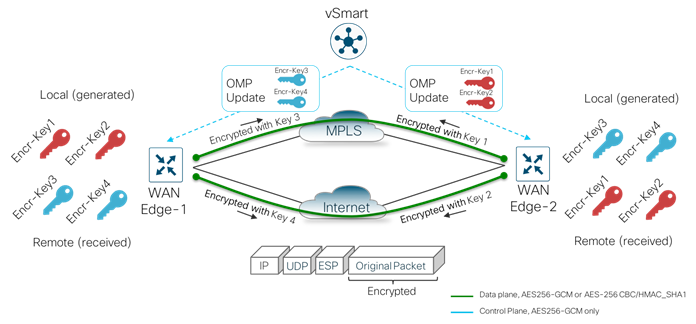
The keys are received by the Catalyst SD-WAN Controller as an OMP update and reflected to the receiving WAN Edge device (WAN Edge-2) that stores the keys as encryption key 1 and encryption key 2 from the remote device. Similarly, WAN Edge-2 also generates its encryption keys and hashing keys, sends it to the Catalyst SD-WAN Controller as an OMP update. The Catalyst SD-WAN Controller reflects the keys to WAN Edge-1, after which the IPsec connections are established over both the transports between the two WAN Edge devices.
As shown in the figure below, the first packet exchanged between the two WAN Edge routers is the actual encrypted data plane packet.
Note that to avoid attackers from predicting the keys, the WAN Edge device changes the AES key used to establish the secure IPsec connection to another WAN Edge device, based on the rekey timer set. By default, the rekey timer is set to 24 hours. This value is equivalent to the security association (SA) lifetime.
For additional details on data plane security and other security topics , refer https://www.cisco.com/c/en/us/td/docs/routers/sdwan/configuration/security/vEdge/security-book/security-overview.html.
In Cisco SD-WAN security, the term segmentation is interchangeably used for Virtual Private Networks (VPN/VRF) to segment users and Zones to create separate security zones.
Virtual Private Network (VPN/VRF)
All Cisco SD-WAN designs are based on the use of VPNs to segment the routing table.
In Cisco SD-WAN, VPN 0 is the transport VPN and VPN 512 is the management VPN. In WAN Edge devices, each VPN is a VRF and completely isolated from one another. The WAN Edge routers maintain a separate FIB for each VPN and the VPN label is carried within the data tunnels to maintain end-to-end segmentation.
All VPNs other than VPN 0 and VPN 512 are used to carry data traffic across the overlay network. VPNs 1-511 and 513-65530 (except 65526, 65528, 65529 and 65530) can be configured as a service-side VPN. For these VPNs to operate, each one must have an operational interface (or sub-interface). The remainder of what is configured in these VPNs depend on the network needs.
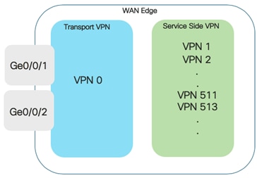
VPN’s 65526, 65528, 65529 and 65530 are reserved VPNs and cannot be configured as a service-side VPN. For instance, VPN 65529 is used as a part of the IPS feature within the management virtual port group (VPN 65526 is used for this purpose starting in Catalyst SD-WAN Manager/IOS XE SD-WAN code versions 20.9/17.9).
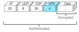
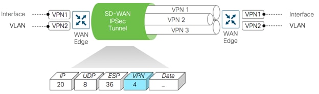
Within the data plane, segmentation is delivered by multiplexing traffic belonging to different VPNs inside a common IPsec tunnel running between WAN Edge routers. VPN labels, which are placed just behind the ESP header, identifies which VPN the user's traffic belongs to when it reaches the remote destination. As the remote router decapsulates the encrypted data, the label is used to determine which VPN to deliver the traffic to.
A zone is a grouping of one or more VPNs. Grouping VPNs into zones establishes security boundaries in the overlay network to control the flow of all data traffic that passes between the zones.
Zone configuration consists of the following components:
● Source zone is a grouping of VPNs where the data traffic flows originate.
● Destination zone is a grouping of VPNs where the data traffic flows terminate.
● Firewall policy is a localized security policy that defines the set of rules that govern traffic from source to destination zone. The possible actions in each rule include pass, inspect and drop.
● Zone pair is a container that associates a source zone with a destination zone and that applies a firewall policy to the traffic that flows between the two zones.
The following sections cover the Cisco SD-WAN security design components and some important design considerations to take while deploying Cisco SD-WAN security features.
Enterprise Firewall with Application Awareness Security Policy
Enterprise Firewall with Application Awareness security policy is a localized security policy that allows stateful inspection of data traffic flows that are matched based on the six different match criteria available within the Catalyst SD-WAN Manager security policy dashboard. The match criteria includes source data prefix, destination data prefix, source port, destination port, protocol and application/application family. Traffic flows that originate in a given zone are allowed to proceed to another zone based on the policy match/action criteria set between the two zones.
Within a given firewall policy, accepted matching flows can be subjected to the following three actions:
● Inspect: When the action is set to Inspect, the firewall feature tracks the state of the flows and creates sessions. Since it maintains the state of the flows, the return traffic is allowed and there is no need to configure a separate policy for return traffic.
● Pass: This action allows the router to forward the traffic from one zone to another zone. The pass action does not track the state of the flows i.e. the firewall does not create sessions when the action is set to Pass. Pass action allows for the traffic flow in only one direction.
● Drop: When the action is set to drop and packets match against the set match parameters, that packet will be dropped.
Based on the flow of traffic between zones, this firewall feature is further divided into Intra-zone-based security and Inter-zone-based security.
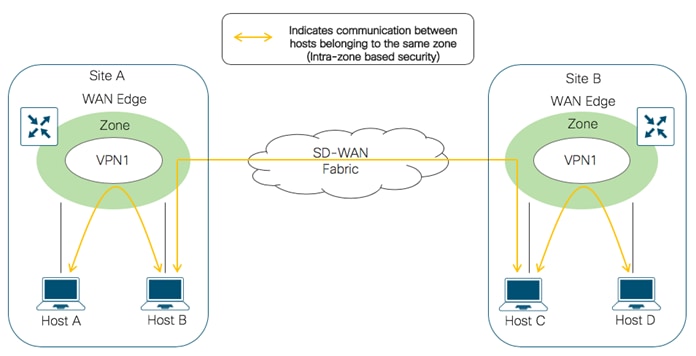
If the flow of traffic is between two zones both tied to the same VPN, that is defined as an Intra-zone firewall. The following figure shows the flow of traffic between the zone-pair (VPN 1 to VPN 1).
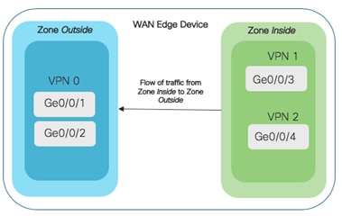
If the flow of traffic is between the two different zones tied to different VPNs, that is classified as an Inter-zone firewall. The following figure shows the flow of traffic between the zone-pair (VPN 1 & VPN 0).

| Technical Tip |
| To leak traffic between VPNs, you must configure either a separate policy or a route command. The traffic flow routed between different VPNs is then inspected by the firewall policy |
Design Considerations for Cisco SD-WAN Enterprise Firewall with Application Awareness
The following are some of the considerations to look into before deploying Enterprise Firewall with Application Awareness on your WAN Edge device.
Supported Platforms and Software
The following table indicates the Enterprise Firewall with Application Awareness support for various platforms with different memory configurations.
Table 6. Supported Platforms – Enterprise Firewall with Application Awareness
| Platform |
Enterprise Firewall |
Enterprise Firewall with Application Awareness |
| Cisco ISR4K Series (4461, 4451, 4431, 4351, 4331, 4321, 4221-X) |
Y |
Y |
| Cisco ISR1K Series and ISR1100X-4G/6G |
Y |
Y |
| Cisco ASR1K (1001-HX, 1002-HX, 1001-X, 1002-X) |
Y |
Y |
| Cisco C8000v |
Y |
Y |
| Cisco Catalyst 8200L Series3 |
Y |
Y |
| Cisco Catalyst 8200, 8300 Series (C8300-2N2S-4T2X/6T, C8300-1N1S-4T2X/6T) |
Y |
Y |
| Cisco Catalyst 8500 Series (C8500L-8S4X) |
Y |
Y |
| Cisco Catalyst 8500 Series (C8500-12X, C8500-12X4QC) |
Y |
Y |
Design IP Addressing Schema & Lists of Interest
For ease of deployment, design your IP addressing schema and preconfigure data prefixes, zones, application families and other lists of interest to be later used and matched in the firewall security policy. All of these match parameters are configured under lists within the firewall security policy.
Note, the lists of Interest specific to the firewall policy include application, data prefix and zones.
For a firewall policy to take effect, you include it in the definition of a zone pair. A zone pair is a container that associates a source zone with a destination zone and that applies a firewall policy to the traffic that flows between the two zones. While designing your zone pairs, note that a VPN can be a part of only one zone. For e.g. VPN1 cannot be configured as a part of two different zones.
The following figure shows a simple example of a zone pair in which three VPNs are configured in an IOS- XE SD-WAN router. One of the VPNs, VPN 3, has shared resources that you want to restrict access to. These resources could be printers or confidential customer data. For the remaining two VPNs in this scenario, only users in one of them, VPN 1, are allowed to access the resources in VPN 3, while users in VPN 2 are denied access to these resources. In this scenario, we want data traffic to flow from VPN 1 to VPN 3, but we do not want traffic to flow in the other direction, from VPN 3 to VPN 1.
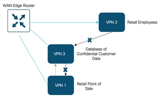
| Technical Tip |
| Since zone-based policies are directional and provides directional control of traffic, it is important to make sure that the direction of traffic flow between the zone-pair is as per design. |
Starting from version 16.12.1a on IOS XE SD-WAN devices, self zone can be used within the zone-pair. The self zone is a firewall zone that contains all of the router interfaces IP addresses. This also includes those interfaces that are not attached to any specific zones. Since, it includes all IP addresses belonging to the router, the self zone can be considered as the router itself. So, when self zone is used as a part of the zone pair, it means traffic to the router or traffic from the router.
You can use self-zone in the zone pair if the intention is to protect your router from any attack. Such as to,
● Prevent unauthorized access.
● Protect the router from inbound threats.
● Restrict communication to the router interfaces.
● Protect the router from DDoS attacks.
● Restrict IPS Signature & URL updates from untrusted hosts.
| Technical Tip |
| You do not have to manually create the self-zone. It is available in the list of zones by default, you just need to call it. For e.g. self-zone can be added in a zone-pair as zone 1 to self-zone or self-zone to zone 1. However, note, if you are defining a ZBFW rule from self-zone to VPN0 and are using Unified Threat Defense (UTD) features like URL-Filtering (URLF), you must explicitly allow traffic from 192.0.2.1 to 192.0.2.2 in your ZBFW rule. These IP addresses are used for UTD channel communication. Otherwise, communication with the UTD engine will fail, and the Service Node will be reported as DOWN. |
Designing Firewall Policy Sequence
While designing firewall policies, confirm that desired actions are taken on the items subject to the policy. A firewall policy consists of a series of numbered (ordered) sequences of match-action pairs that are evaluated in order, from lowest sequence number to highest sequence number. When a data packet matches the match conditions, the associated action or actions are taken and policy evaluation on that packet stops.
The firewall policy is configured via Catalyst SD-WAN Manager Security Policy GUI and applied to a WAN Edge device via templates. The configuration within your WAN Edge device mainly contains a combination of class-map, policy-map and class.
Note: The number of classes per policy map for each platform is as given below,
ASR: up to 1000 classes per policy-map.
CSR: up to 512 classes per policy-map.
ISR: up to 256 classes per policy-map (reserved one for class-default, so only 255 user-defined classes allowed).
| Technical Tip |
| For a sequence that contains an application or application family list, the action must be set to inspect. Matching applications are blocked/denied. Note: On choosing Pass/Drop action, the following error message is displayed “Action must be Inspect when Application/Application Family List is selected. Please change the Action”. |
If the default rule within the firewall policy is set to drop, then a packet that matches none of the configured sequence rules will be dropped.
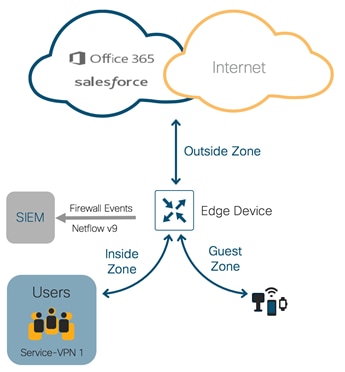
For WAN Edge devices running IOS-XE SD-WAN Code 16.12 or higher, High Speed Logging (HSL) can be enabled. When HSL is configured, the firewall provides a log of packets that flow through the devices (similar to the NetFlow Version 9 records) to an external collector, with minimum impact to packet processing. Records are sent when sessions are created and destroyed within WAN Edge device. Session records contain full 5-tuple information that includes the source IP address, destination IP address, source port, destination port, and protocol.
In Cisco SD-WAN, the firewall logs the following types of events:
● Audit: Session creation and removal notifications.
● Alert: Half-open and maximum-open TCP session notifications.
● Drop: Packet-drop notifications.
● Pass: Packet-pass notifications.
● Summary: Policy-drop and pass-summary notifications.
By default, High-Speed Logging (HSL) is not enabled and firewall logs are sent to a log buffer located in the Route Processor (RP) or the console. With HSL enabled, logs are sent to an off-box, high-speed log collector. The collector can be placed either within the organization network or outside based on the design requirement.
| Technical Tip |
| HSL uses NetFlow version 9 template to log IPv4 NetFlow packets to only one HSL destination or NetFlow collector. |
Note, you can only log inspected traffic by enabling High Speed Logging (HSL) to external server as a NetFlow record. For this you need to configure HSL with the NetFlow collector details and enable Audit Trial in the policy summary page
Enable Audit Trail to record the start, stop, and duration of a connection or a session, along with the source and destination IP addresses. Note, this option is only applicable for rules with an inspect action, and available IOS-XE SD-WAN devices running 16.12 and Catalyst SD-WAN Manager code version 19.2.0.
For additional information about Audit trail refer to the Firewall High Speed Logging document.
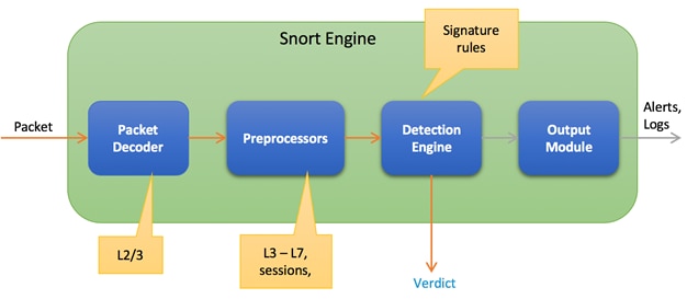
The next few sections focus on the design conversation around Intrusion Prevention System (IPS), URL Filtering and Advanced Malware Protection (AMP). Note, these security features are implemented using the Snort virtual container service. So before diving into the container based security features, the upcoming section explains the architecture and working of the Snort Engine.
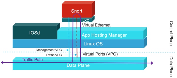
The IOS XE SD-WAN devices have a multi-core CPU architecture, where some cores are allocated for control plane and other cores for service/forwarding plane. Snort is running as a container application in the control plane infrastructure and it uses some of the CPU cores allocated for the control plane. The built-in or Application hosting manager or Virtualization Manager (VMAN) within the control plane ensures that applications running on the containers and IOS daemon (IOSd) get a fair share of computer resources.
There are two virtual ports or interfaces connecting to the Snort container; the Management Virtual Port Group (Management VPG) and the Traffic Virtual Port Group (Traffic VPG). The first Virtual Port Group (VPG) is used for management traffic; this VPG is used to source logs to the log collector as well as to pull signature updates from Cisco.com. The second Virtual Port Group is for data traffic between the forwarding plane and the Snort virtual container service; This VPG is used to send and receive packets that are marked for inspection that arrive on the data plane. These packets are sent back and forth to the container.
Snort traffic inspection is enabled for one or many selected target VPNs. After the policy is defined, traffic is redirected from the data plane to the container that contains the snort sensor. Snort then inspects the traffic for threats. Traffic posing threat to the network is dropped and the remaining is forwarded back to the router for further processing.
An Intrusion Prevention System (IPS) detects and blocks known network attacks. It uses previously known signatures, which are basically a set of rules to detect attacks originating from both external and internal sources.
Snort is an open source network Intrusion Prevention System (IPS) leveraged within Cisco IOS-XE SDWAN devices to perform real-time traffic analysis and generate alerts when threats are detected on IP networks. Within the Cisco SD-WAN solution, IPS is an on-box, on-prem feature which provides PCI compliance.
Based on your network requirements, you can enable Snort either in Intrusion Prevention Mode (IPS) or Intrusion Detection Mode (IDS) and Snort performs the following actions:
● Monitors network traffic and analyzes it against a defined rule set.
● Performs attack classification.
● Invokes actions against matched rules.
In IDS mode, Snort inspects the traffic and reports alerts, but does not take any action to prevent attacks. In IPS mode, in addition to Intrusion detection, actions are taken to prevent attacks
| Technical Tip |
| By default, the protection mode is set to Detection within the Cisco SD-WAN IPS Policy. |
Design Considerations for Cisco SD-WAN IPS Solution
The following are the main components within the Snort IPS Solution that needs to be considered while designing the IPS/IDS security policy.
For Intrusion Prevention (features that leverage the Security Virtual Image - UTD file), platforms must meet the minimum requirements of 8 GB flash memory and 8 GB DRAM. Make sure to choose a platform that supports the IPS functionality. Refer to the table for details.
Table 7. Supported Platforms – IPS/IDS
| Platform |
IPS/IDS |
| Cisco ISR4K Series (4461, 4451, 4431, 4351, 4331, 4321, 4221-X) |
Y |
| Cisco ISR1K Series and ISR1100X-4G/6G |
Y |
| Cisco ASR1K (1001-HX, 1002-HX, 1001-X, 1002-X) |
N/A |
| Cisco C8000v |
Y |
| Cisco Catalyst 8200L Series3 |
N/A |
| Cisco Catalyst 8200, 8300 Series (C8300-2N2S-4T2X/6T, C8300-1N1S-4T2X/6T) |
Y |
| Cisco Catalyst 8500 Series (C8500L-8S4X) |
Y |
| Cisco Catalyst 8500 Series (C8500-12X, C8500-12X4QC) |
N/A |
The number of cores is assigned based on the total number of cores available per device to host the container profile (for security app hosting).
| Technical Tip |
| ASR1Ks will not get the IPS functionality. The available control plane cores are not sufficient to process all the packets that the ASR1K is capable of processing. |
To enable Snort IPS, make sure your WAN Edge device is running IOS XE SD-WAN version 16.10 or higher, along with a compatible (recommended) UTD engine code and control components running code 18.4 or higher.
We only support the UTD package that is released at the same time as the IOS-XE SD-WAN code. We call this the ‘Recommended Version’. For the recommended UTD code version, navigate to Monitor > Network > Real Time. Enter Security App Version Status under Catalyst SD-WAN Manager Device Options and find the Recommended Version. In the example, the Security Virtual Image for ISR4331 running 16.12.1d code is displayed.
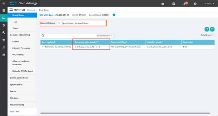
In the above figure, the third column displays the Supported Regex pattern. The supported regex is the range of compatible virtual image versions for the router image. In this example, for a device running 16.12 IOS-XE SDWAN code, any virtual image from version 1.0.[0-9]+_SV(*)_XE16.12 onwards can be used. In this example, the [0-9]+ portion is the regex to denote that any SV image with version 1.0.X is compatible on the WAN Edge device.
Note: Regex means that the virtual image version has to end as _XE16.12. So basically, you can only use a 16.12 virtual image with a 16.12 IOS-XE SD-WAN code. The Snort engine version that comes after “SV” in the version string works as long as it ends as 16.12 for the router running 16.12 IOS-XE SD-WAN code.
Snort sensor and Catalyst SD-WAN Manager Virtual Image Repository
To enable Snort IPS, it is required to download the Unified Threat Defense (UTD) Engine from software.cisco.com into the Catalyst SD-WAN Manager virtual image repository.
The virtual container images are downloaded from Catalyst SD-WAN Manager to the WAN Edge device to bring up the container with Snort enabled. The Snort sensor is deployed within the router as a virtual container service that monitors the traffic to detect anomalies based on the configured security policy (that includes signatures, statistics, protocol analysis, and so on) and sends log messages to the log server.
| Technical Tip |
| To bring up UTD services, WAN Edge device downloads the Recommended Version if present from the Catalyst SD-WAN Manager Repository. If not available, then the package that matches the Supported Regex is used. If no UTD packages that meet this regex pattern are found in the repository, then the UTD installation is aborted. |
Snort Virtual Services and NAT
The Management Virtual Port Group (VPG) is configured by default in VRF 65529 (or VRF 65526 starting in Catalyst SD-WAN Manager/IOS XE SD-WAN code versions 20.9/17.9). Note, within the WAN Edge configuration, if IP NAT route is configured to route traffic from the Management VPG port to the global routing table in VPN 0 WAN transport Interface (and not route via policy from Management VPG port to service-side VPN), then enable the NAT feature on the VPN 0 WAN Edge transport interface for that traffic to exit. It is required to route traffic from Management VPG port to the global routing database only if the virtual services such as IPS need to go to the Internet for manual signature updates or if there is a need to send IPS syslog’s to an external syslog server reachable from VPN 0.
The IP subnet of the second VirtualPortGroup (Traffic VPG) interface need not be routable on the customer network because the traffic on this interface is internal to the router. Exposing the internal subnet to the outside world is a security risk. We recommend the use of the 192.0.2.0/30 IP address range for the second VirtualPortGroup subnet.
Signatures are a set of rules that an IDS and IPS security policy uses to detect typical intrusive activity.
While designing the Snort IPS policy it is important to understand the signature levels available within your Catalyst SD-WAN Manager IPS policy. There are three signature levels available within the Catalyst SD-WAN Manager IPS Policy – Security, Balanced and Connectivity. Each of the signature levels contain a list of security vulnerabilities categorized based on the score assigned using the Common Vulnerability Scoring System (CVSS).
Note: Common Vulnerability Scoring System (CVSS) is a free and open industry standard for assessing the severity of security vulnerabilities.
The three signature levels available within Catalyst SD-WAN Manager IPS are as given below,
Connectivity: This signature set contains rules from the current year and the previous two years for vulnerabilities with a CVSS score of 10.
Balanced: This is the default signature set and contains rules that are from the current year and the previous two years.
This signature set is for vulnerabilities with a Common Vulnerability Scoring System (CVSS) score of 9 or greater, and its categories include:
Table 8. Balanced Signature Set
| Category |
Definition |
| Blacklist |
Rules for URIs, user agents, DNS hostnames, and IP addresses that have been determined to be indicators of malicious activity. |
| Exploit-kit |
Rules that are designed to detect exploit kit activity. |
| Malware-CNC |
Rules for known malicious command and control activity for identified botnet traffic. These include call home, downloading of dropped files, and ex-filtration of data. |
| SQL Injection |
Rules that are designed to detect SQL Injection attempts. |
Security: The signature set contains rules from the current year and the previous three years. This signature set is for vulnerabilities with a CVSS score of 8 or greater, and its categories include.
Table 9. Security Signature Set
| Category |
Definition |
| App-detect |
Rules that look for and control the traffic of certain applications that generate network activity. |
| Blacklist |
Rules for URIs, user agents, DNS hostnames, and IP addresses that have been determined to be indicators of malicious activity. |
| Exploit-kit |
Rules that are designed to detect exploit kit activity. |
| Malware-CNC |
Rules for known malicious command and control activity for identified botnet traffic. These include call home, downloading of dropped files, and ex-filtration of data. |
| SQL Injection |
Rules that are designed to detect SQL Injection attempts |
| Technical Tip |
| IPS does not work on encrypted traffic (HTTPS). |
Before choosing the signature set, make sure to whitelist performance impacting signatures. The next section focuses on signature whitelisting.
Signatures are whitelisted to reduce the number of false positives i.e. to reduce the chance of a non-harmful file being detected as a malware.
The signature whitelist format on Catalyst SD-WAN Manager is Generator Identifiers: Signature Identifiers.
Generator Identifiers (GID): The Generator Identifier (GID) identifies the subsystem or the part of snort that evaluates an intrusion rule and generates events when a particular rule is hit. For example, standard text intrusion rules have a generator ID of 1, and shared object intrusion rules have a generator ID of 3. There are several other sets of rules for various preprocessors. The following table explains some of the GIDs.
Table 10. GID and Components
| GID |
Components |
| 1 |
Standard Text Rule |
| 2 |
Tagged Packets (Rules for the Tag generator, which generates packets from a tagged session) |
| 3 |
Shared Object Rule |
| 102 |
HTTP Decoder |
| 105 |
Back Orifice Detector |
| 106 |
RPC Decode Preprocessor |
| 112 |
Arpspoof Preprocessor |
| 116 |
Packet Decoder/ Snort Decoder |
| 119, 120 |
HTTP Inspect Preprocessor (GID 120 rules relate to server-specific HTTP traffic.) |
| 122 |
Portscan Preprocessor |
| 123 |
IP Defragmentor |
| 124 |
SMTP Decoder (Exploits against SMTP verbs.) |
| 125 |
FTP Decoder |
| 126 |
Telnet Decoder |
| 127 |
ISAKMP Preprocessor |
| 128 |
SSH Preprocessor |
| 129 |
Stream Preprocessor |
| 131 |
DNS Preprocessor |
| 132 |
Skype Preprocessor |
| 133 |
DCE/RPC Preprocessor |
| 134 |
Rule Latency, Packet Latency (PPM Preprocessor) (Events for these rules are generated when rule latency suspends (SID 1) or re-enables (SID 2) a group of intrusion rules, or when the system stops inspecting a packet because the packet latency threshold is exceeded (SID 3)) |
| 135 |
Rate-Based Attack Detector (Excessive connections to hosts on the network) |
| 137 |
SSL Preprocessor |
| 138, 139 |
Sensitive Data Preprocessor |
| 140 |
SIP Preprocessor |
| 141 |
IMAP Preprocessor |
| 142 |
POP Preprocessor |
| 143 |
GTP Preprocessor |
| 144 |
Modbus Preprocessor |
| 145 |
DNP3 Preprocessor |
Signature Identifier (SID): Snort Identifier (SID), also called Signature Identifier is used to uniquely identify the Snort rules. This information allows output plugins to identify rules easily.
Identify SID and GID value: The following methods list some ways to find the SID and GID associated with a signature to be whitelisted,
● Download the signature package from Cisco Software Central and rename the downloaded file format from .pkg to .tar. An example of a signature package is:
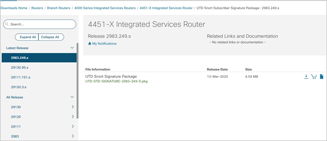
Extract the renamed TAR file and click on the Rules folder contained in the unzipped file to view the signature rules associated with the signature sets.
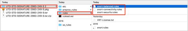
Within each signature rule, you can look for Signature ID (SID) associated with the Signatures to be whitelisted.
The following is an example of a signature rule that is a part of the Balanced signature set.
# -- Begin GID:1 Based Rules -- #
drop tcp $EXTERNAL_NET $FILE_DATA_PORTS -> $HOME_NET any (msg:"BROWSER-IE Microsoft Internet
Explorer 9 onbeforeprint use after free attempt"; flow:to_client,established; file_data; content:"onbeforeprint"; fast_pattern:only; content:"document.write"; pcre:"/<script.*?function\s*(?P<func>\w*)\s*\x28\x29.*?\x7b[^\x7d]*?document\x2ewrite.*?<body.
*?onbeforeprint\s*=\s*[\x22\x27]?(?P=func)/smi"; metadata:policy balanced-ips drop, policy
max-detect-ips drop, policy security-ips drop, service ftp-data, service http, service imap,
service pop3; reference:cve,2013-0092; reference:url,technet.microsoft.com/en-us/security/
bulletin/ms13-021; classtype:attempted-user; sid:26157; rev:5;)
Table 11. Keyword and Description of a Signature Rule
| Keyword |
Description |
| MSG |
The keyword msg is used to alert the engine to print a message. |
| REFERENCE |
The keyword reference is used to enable Snort rules to include references to external attack identification systems. |
| GID (Generator Identifier) |
The Keyword GID is used to identify the part of Snort that generates an event when a particular rule is hit. |
| SID (Signature Identifier) |
The keyword SID is used to uniquely identify Snort rules. |
| REV |
The keyword REV is used to uniquely identify revisions of Snort rules. |
| CLASSTYPE |
The keyword classtype is used to categorize a rule as detecting an attack that is part of a more general type of attack class. |
| METADATA |
The keyword metadata is used to allow a rule writer to embed additional information about the rule, typically in a key-value format. |
● SID’s and GID’s can also be copied from the generated alert logs. You can find the associated SID and GID of a signature from,
◦ WAN Edge UTD logs (show utd engine standard logging events)
◦ The IPS logs generated on the syslog server.
◦ The Catalyst SD-WAN Manager event logs (Monitor > Network > Events)
For example,
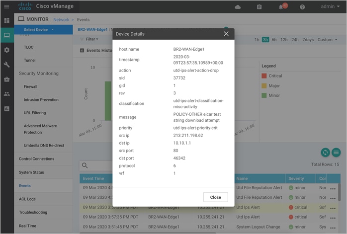
Note, the whitelist signature format is GID: SID. For example, 1:37732.
● Alternatively, you can also view SID and GID value via the following CLI command. These commands copy the list of active signatures available in the Catalyst SD-WAN Manager and copy’s a summary of the total number of active signatures, drop signatures, and alert signatures into a text file in the flash.
1) utd threat-inspection signature active-list write-to bootflash:<filename.txt> threat-inspection profile <ips profile name> //to copy the signatures into a text file (.txt)//
2) more bootflash:<filename.txt> //to view the contents of the file//
| Technical Tip |
| There is a known issue on 16.12 code wherein the signature write-to command may fail, if the IPS profile name associated with the UTD threat-inspection command is in upper-case characters. The workaround is to set the IPS profile name in lower-case characters and associate that profile with the UTD threat-inspect signature write-to command. |
Example output:
BR2-WAN-Edge1#utd threat-inspection signature active-list write-to bootflash:sig.txt threat-inspection profile dia_ips_policy
BR2-WAN-Edge1#more bootflash:sig.txt
=================================================================================
Signature Package Version: 29130.103.s
Signature Ruleset: Security
Total no. of active signatures: 16845
Total no. of drop signatures: 16172
Total no. of alert signatures: 673
For more details of each signature please go to www.snort.org/rule_docs to lookup
=================================================================================
List of Active Signatures:
--------------------------
sigid: 13359, gid:1, log-level:3, action: alert, class-type: misc-activity,
Descr: APP-DETECT failed IMAP login attempt - invalid username/password;
sigid: 21488, gid:1, log-level:1, action: drop, class-type: trojan-activity,
Descr: APP-DETECT User-Agent known user agent - GetRight;
sigid: 24397, gid:1, log-level:1, action: drop, class-type: policy-violation,
Descr: APP-DETECT Steam game URI handler;
| Technical Tip |
| Snort IDs (SID) lower than 1000000 are created by the Cisco Talos Intelligence Group (Talos). |
Choosing the Right Signature Set
Signature set refers to rules/signatures that have been developed, tested and approved by the Talos Security Intelligence and Research Team (Talos). Before you choose the signature set, have a complete understanding of the network, devices and traffic flows that your signature set is bound to protect. There are performance-impacting signatures, hence work your way up from the Balanced signature set after having whitelisted sensitive application flows via Signature Whitelist on Catalyst SD-WAN Manager.
Connectivity: Less restrictive with better performance as there are fewer rules attached to this signature level.
Balanced: Designed to provide protection without a significant effect on system performance.
Security: With more added rules, this signature level offers the most protection.
Basically, Connectivity has the least number of signatures, Security has the most number of signatures and Balanced striking a ‘balance’.
The signature store hosts the Cisco signature packages that are updated periodically. After the UTD Tar file (Security Virtual Image) is downloaded into WAN Edge device from the Catalyst SD-WAN Manager Repository, by default the signature set is in .c format or Community Signature Set format. This signature format must be updated to Subscription Signature Set or .s.
Validated signature packages are posted to Cisco.com. These signature packages are downloaded to sensors either periodically or on demand, converting the package from Community Signature Set to Subscription Signature Set on the Edge device.
Signature Update
● You can either enable automatic signature update via Catalyst SD-WAN Manager or update it manually via CLI. For automatic signature update, link your CCO username/password within Catalyst SD-WAN Manager IPS Signature Update.
● To manually update the signature package via CLI,
◦ On a WAN Edge device that has reachability to the Internet – Enter CLI command, utd signature update server cisco username <username> password <password>.
◦ On a WAN Edge device with no internet access - Download the signature package from CCO on your local workstation and upload the file to the device’s flash directory. Then, enter the CLI command to update the signature set, utd signature update file bootflash:<signature.pkg>.
When a new signature package is updated, the Snort engine will restart and traffic may be interrupted or may bypass inspection for a short period depending on the data plane fail-open/fail-close configuration.
Design Target VPN for IPS Security Policy
When you create a Cisco SD-WAN IPS security policy, you must specify a target VPN. The target VPN can either be a single VPN or a list of comma-separated VPNs.
When you enable the IPS feature on a single VPN, the corresponding policy is applied to traffic in both directions (from and to that VPN). For example, if you apply the policy to a single VPN, say VPN 3, then the security policy is applied in both the directions.
Note: Policy applied to VPN 0 will only inspect clear traffic that traverses the underlay, not the traffic that is encrypted by the enterprise tunnels. For example, in both the following cases, a VPN 0 security policy does not inspect:
● Traffic originating from a service-side VPN (for example VPN 3) that is transmitted through the enterprise tunnel. This traffic is not inspected because VPN 3 is not explicitly specified in the policy.
● Traffic from the enterprise tunnel that is sent to the service-side VPN (for example VPN 3). This traffic is again not inspected because VPN 3 is not explicitly specified in the policy.
The Fail-close option drops all the IPS/IDS traffic when there is an engine failure. The Fail-open option allows for the flow of traffic bypassing all security features even at the time of an engine failure. The default option is Fail-open. Enable fail-close if security is the concern and select the option fail-open only if connectivity is the concern.
Within the Snort IPS policy the log level can be set and the consequent logs generated by the Snort sensor is sent to a syslog server. The logging level ranges from 0-Emergency to 7-Debug. The higher the level, the more inclusion of granular, diagnostic information. It is ideal to stick to Warning/Error level for balance of load and information at the production site.
The logging levels available as of today are:
Table 12. Alert Log Levels
| Severity |
Log Level |
Type |
| 0 |
Emergency |
System is unusable |
| 1 |
Alert |
Immediate action needed |
| 2 |
Critical |
Critical conditions |
| 3 |
Error |
Error conditions |
| 4 |
Warning |
Warning conditions |
| 5 |
Notice |
Normal but significant conditions |
| 6 |
Info |
Informational messages |
| 7 |
Debug |
Debug messages |
| Technical Tip |
| To find on-box UTD logs within WAN Edge device, enter command - show utd engine standard logging events and to find UTD logs within Catalyst SD-WAN Manager find it within Monitor > Network > Events. |
While attaching the configured IPS policy within a device template, a sub-template titled container profile must be added. The container profile allows you to enable/disable NAT for your virtual services (IPS) and allocate the number of control plane cores for the virtual services.
Regarding the NAT functionality, it can be enabled if the virtual services go out to the internet for manual signature updates on the WAN Edge device or if there is a need to send syslogs to an external syslog server that is not necessarily in the Data Center.
Regarding the Resource profile, by default the profile is set to Default. However, for higher throughput, you may set the resource profile to High. However, before making any changes to the resource profile, confirm the current memory status of your WAN Edge device, as the security app container cannot be installed if the device lacks memory space. Use the show memory platform command to note the free and physical memory status.
Note, from 20.5 release, the resource profiles are categorized as low, medium, or high. For more details on the supported platforms, please refer to the individual platform datasheet.
Catalyst SD-WAN Manager NMS server downloads the container images from the virtual image repository to the WAN Edge device and brings up the container with Snort enabled. Based on the mode and signature level configured, traffic to the target VPN will be either detected or prevented. If the mode is set to prevent, then it detects the signature of the traffic and prevents the flow (if the signature is blacklisted) and based on the log level set, an equivalent report is sent to the syslog server. If the mode is set to detection, then the signature violations are detected and alerts are sent.
| Technical Tip |
| If Enterprise Firewall Application Awareness is configured, Unified Threat Detection (UTD) will be invoked after the firewall policy. |
The Cisco SD-WAN URL Filtering (URLF) feature enables the user to provide controlled access to Internet websites by configuring domain-based or URL-based policies via Catalyst SD-WAN Manager NMS. The localized security policy is pushed from Catalyst SD-WAN Manager into the remote site WAN Edge devices.
Within the policy, you have the option to permit or deny access to websites based on the web category through category-based filtering and/or Web Reputation score through reputation-based filtering. The policy also contains advanced settings to blacklist and/or whitelist specific URLs or domain names.
The types of URL filtering include List-based Filtering, Category-based Filtering and Reputation-based Filtering.
These are rules which helps the user to either allow or deny domains or URLs. The user is provided with controlled access to Internet websites by configuring domain-based or URL-based policies and filters on the device. Domain-based filtering enables the user to control access to websites/servers at domain level, and URL-based filtering enables the user to control access to websites at URL level.
Note, If the same pattern is configured under both whitelist and blacklist, the traffic will be whitelisted.
URLs are classified into 82+ categories such as News, Social Media, Education, Adult and so on. For example, ebay.com belongs to the Auctions category, and monster.com belongs to the Job Search category. Based on the requirements, the user has the option to block or allow websites belonging to one or more categories.
| Technical Tip |
| A website can belong to more than one category. |
Each URL has a web reputation score associated with it that explains the likelihood of a URL being used for purposes that might be against your organization’s security policy. Reputation scores range from 1 to 100, and are split into tiers such as Trustworthy (level 5), Low Risk (level 4), Moderate Risk (level 3), Suspicious (level 2), and High Risk (level 1).
| Technical Tip |
| Filtering a URL based on its reputation score is mandatory. |
Design Considerations for Cisco SD-WAN URL Filtering
Some of the design considerations for Cisco SD-WAN URL Filtering are explained below.
Supported Platforms and Memory
To enable Cisco SD-WAN URL-Filtering (features that leverage the UTD TAR file - Security Virtual Image), platforms must include 8 GB flash memory and 8 GB DRAM.
Make sure to choose a platform that supports the minimum required memory. Refer to the table for details.
Table 13. Supported Platforms – URL Filtering
| Platform |
URL Filtering |
| Cisco ISR4K Series (4461, 4451, 4431, 4351, 4331, 4321, 4221-X) |
Y |
| Cisco ISR1K Series and ISR1100X-4G/6G |
Y |
| Cisco ASR1K (1001-HX, 1002-HX, 1001-X, 1002-X) |
N/A |
| Cisco C8000v |
Y |
| Cisco Catalyst 8200L Series3 |
N/A |
| Cisco Catalyst 8200, 8300 Series (C8300-2N2S-4T2X/6T, C8300-1N1S-4T2X/6T) |
Y |
| Cisco Catalyst 8500 Series (C8500L-8S4X) |
Y |
| Cisco Catalyst 8500 Series (C8500-12X, C8500-12X4QC) |
N/A |
The number of cores are assigned based on the total number of cores available per device for the container profile (security app hosting profile).
To enable URL Filtering (URLF), make sure your WAN Edge device is running IOS XE SD-WAN version 16.10 or higher, along with a compatible (recommended) UTD engine code and control components running code 18.4 or higher.
We only support the UTD package that is released at the same time as the IOS-XE SD-WAN code. We call this the ‘Recommended Version’. For the recommended UTD code version, navigate to Monitor > Network > Real Time. Enter Security App Version Status under Catalyst SD-WAN Manager Device Options and find the Recommended Version. In the example, the Security Virtual Image for ISR4331 running 16.12.1d code is displayed.

In the above figure, the third column displays the Supported Regex pattern. The supported regex is the range of compatible virtual image versions for the router image. In this example, for a device running 16.12 IOS-XE SDWAN code, any virtual image from version 1.0.[0-9]+_SV(*)_XE16.12 onwards can be used. In this example, the [0-9]+ portion is the regex to denote that any SV image with version 1.0.X is compatible on the WAN Edge device.
Note: Regex means that the virtual image version has to end as _XE16.12. So basically, you can only use a 16.12 virtual image with a 16.12 IOS-XE SD-WAN code. The Snort engine version that comes after “SV” in the version string works as long as it ends as 16.12 for the router running 16.12 IOS-XE SD-WAN code.
Snort Sensor and Catalyst SD-WAN Manager Virtual Image Repository
To enable Snort, it is required to download the Unified Threat Defense (UTD) Engine from software.cisco.com into the Catalyst SD-WAN Manager virtual image repository.
The virtual container images are downloaded from Catalyst SD-WAN Manager to the WAN Edge device to bring up the container with Snort enabled. The Snort sensor is deployed within the router as a virtual container service that monitors the traffic to detect anomalies based on the configured security policy (that includes signatures, statistics, protocol analysis, and so on) and sends log messages to the log server.
| Technical Tip |
| To bring up UTD services, WAN Edge device downloads the Recommended Version if present from the Catalyst SD-WAN Manager Repository. If not available, then the package that matches the Supported Regex is used. If no UTD packages that meet this regex pattern are found in the repository, then the UTD installation is aborted. |
Design URL Filtering Policy with Web Categories
Note, URL filtering is not the same as Cisco Umbrella but a completely separate product. It is an on-device feature using bright cloud database. When you configure URL filtering, you first choose to block or allow specific web category(s). Refer to the Categories Data Sheet to gather details regarding the category and description of each web category.
| Technical Tip |
| To change the web category of a particular URL, navigate to brightcloud. Enter a URL (example.com) and click on the checkbox I’m not a robot, you will then be navigated to a page wherein you can fill in details regarding the URL and category. After the form is submitted, it takes anywhere from 24 to 48 hours for change requests to be processed. If you did fill in your email in the form, you will receive an email that confirms the submission, followed by another email when the request is completed. |
Design URL Filtering Policy with Web Reputation
The web reputation tiers range from Trustworthy (level 5), Low Risk (level 4), Moderate Risk (level 3), Suspicious (level 2), and High Risk (level 1).
The Web Reputation score for each of the tiers is as follows.
● Reputation score of 01-20 is categorized as High Risk. These high risk IP addresses are predicted to deliver attacks such as DoS attacks, malicious payload or others to your infrastructure and endpoints.
● Reputation score of 21-40 is categorized as Suspicious. These suspicious IP addresses are predicted to deliver attacks to the endpoint.
● Reputation score of 41-60 is categorized as Moderate Risk. These are generally benign IP addresses that have exhibited some potential risk characteristics. These IP addresses are predicted to deliver attacks to endpoints.
● Reputation score of 61-80 is categorized as Low Risk. These are benign IP addresses that have rarely exhibited characteristics that expose the endpoint to security risks. These IP addresses are predicted to be of low risk.
● Reputation score of 81-100 is categorized as Trustworthy. These are clean IP addresses are not associated to a security risk. These IP addresses are predicted to be of very low risk to the endpoint.
While setting the web reputation level, note that URL with scores higher than the chosen reputation tier is allowed. For example, If the Web Reputation level is set to Low Risk, all websites with a reputation score of Low Risk and higher such as Trustworthy are allowed.
Numerically lower scores (higher risk) indicate IPs that are more likely to become a threat, and are monitored at a greater frequency than trustworthy IPs. If the web reputation score is specified as moderate risk in Catalyst SD-WAN Manager, all websites with a reputation score of moderate risk and higher (low risk and trustworthy) are allowed.
The reputation levels enable enterprises to finely tune their security settings based on their risk tolerance and business needs. This enables them to proactively prevent attacks by limiting the exposure of their networks to dangerous IPs.
| Technical Tip |
| Some technical tips to note, 1) When you build a URL rule, you first choose the category you want to match. If you explicitly choose Uncategorized as the category, you cannot further constrain URLs by reputation. This is because Uncategorized categories do not have reputations associated with it. 2) Without connectivity to the Internet, you cannot use the reputation/category features of URL filtering, however you can still use whitelist/blacklist. 3) The default URL category/reputation database only has a few IP address based records. The category/reputation look up occurs only when the host portion of the URL has the domain name. |
Design Policy with URL Blacklist/ Whitelist rules
Only regex patterns are supported within URL blacklist/whitelist and currently 64 patterns are supported. A user may consider using a combination of a whitelist and blacklist pattern to design the filters. To whitelist or blacklist a URL or domain, some of the possible combinations to enter website details within the Catalyst SD-WAN Manager include .*website1.com or .*.website1.com.
Design Target VPN for Cisco SD-WAN URL Filtering
When you create a URL Filtering security policy, you must specify a target VPN. The target VPN can contain either a single VPN or a list of comma-separated VPNs. When you enable URL Filtering features on a single VPN, the corresponding policy is applied to both, traffic from and to the VPN.
Cisco SD-WAN URL Filtering for HTTP/ HTTPS Traffic
For HTTP traffic, the router performs URL filtering for plain text traffic (either HTTP traffic or decrypted HTTPS traffic).
However, for HTTPS traffic, we analyze the packet until encryption starts. The router determines the URL based on the information passed during the TLS/SSL handshake. The server hello packet is examined to block/allow the domain name based on the server certificate. It is not possible to inspect the full URL path.
Security App Hosting Template & URL Database
URL Filtering uses Snort preprocessors to extract the URLs from HTTP/HTTPS traffic. Hence, while attaching the configured URL Filtering Policy within the device template, a sub-template titled container profile is added. Note, the Resource Profile within the container template, by default is set to Default settings which is one or two cores. For performance improvement, you may set the resource profile to High allocating two cores.
Catalyst SD-WAN Manager does not download the URL database from the cloud by default. If the Resource Profile within the container template is set to Default, the first URL query is always sent to the Webroot cloud, the result from the cloud lookup is stored in the local cache so subsequent hits do not go out to the cloud.
For instance, if the resource profile is set to Default and a client was to visit cnn.com, request for the web category associated to the website cnn.com is sent to the cloud or Webroot. The response received from the Webroot, news and media is cached. Subsequently, if the same client or a different client sitting behind the same edge was to visit cnn.com, rather than sending the request to Webroot, the cache entry is checked.
If the Resource Profile is set as High within the container profile, then the URLF database will be on-box. After the entire database is downloaded from the cloud, if there are any updates to the existing database, the incremental updates are automatically downloaded.
However, note, If the URL is not found within the database, then the query is sent to cloud for lookup.
Note, URL database download is monitored every 5 minutes, and typically every 15 minutes there is an incremental update, and every 24 hours the database is fully updated.
The downloaded database should always synchronize with the cloud. The database will be invalid if the connection to the cloud is lost for more than 24 hours.
However, before making any changes to the resource profile, confirm the memory requirement of your WAN Edge device, as the security app container cannot be installed if the device lacks memory space. Devices with 8GB DRAM/ Flash, have an additional 4GB memory for the control plane cores to run the container services. However, the additional 4GB memory is insufficient to download the entire URL filtering database.
By deploying a platform with 16GB DRAM/ flash, you now have enough control plane cores available for service plane with an additional 8 GB memory. For more details on the supported platforms and memory requirements for resource profile, refer to the individual platform datasheet.
| Technical Tip |
| Within the URL cache, each URL entry is stored along with its associated results such as categorization and reputation score. Each entry is 44 bytes and 80 MB of the container is used for caching purpose, hence the cache memory can hold up to 1.8 million URL entries. |
URL Database in Cisco SD-WAN URL-Filtering security policy
The URL database is downloaded from database.brightcloud.com at port 443, while the unknown URL queries are done at service.brightcloud.com at port 80.
The first type of updates are Real Time Updates (RTU), which are delivered throughout the day every 5 minutes. These updates do not modify the base database file, but are rather recently classified URLs, specifically URLs classified into one of our security related categories (Bot Nets, Malware, Phishing & other Fraud, Proxy Avoidance & Anonymizers, Spam URLs, Spyware & Adware). These updates are published throughout the day and added to an RTU cache.
The other type of update is the update to the database file. This is an update that includes any differences to the current local database. This is published once a day.
| Technical Tip |
| The container upgrade and installation procedures are the same as IPS/IDS. |
If the WAN Edge device fails to receive the URL database updates from the cloud, the fail-open option ensures that the traffic designated for URL filtering is not dropped. With fail-close option, all the traffic destined for URL Filtering will be dropped when the cloud connectivity is lost.
Also, note the Fail-close option drops all the UTD traffic when there is an engine failure, while the Fail-open option allows for the flow of traffic bypassing all security features even at the time of an engine failure. The default option is Fail-open. Enable fail-close if security is the concern and select the option fail-open only if connectivity is the concern.
A server can be hosted either on the cloud or in the datacenter to export URL Filtering logs. Note, while Firewall logs are exported in NetFlow v9 format, URL Filtering logs are exported in Syslog/ UDP format.
By default, Catalyst SD-WAN Manager provisions a container that uses OpenDNS servers, 208.67.222.222 and 208.67.220.220. Therefore, make sure the Domain Name System (DNS) traffic to resolve api.bcti.brightcloud.com is not dropped along the path between the container and the umbrella DNS servers. Always ensure both DNS servers are reachable.
If any IP name servers are configured within the WAN Edge device, then these server IP’s are passed to the container and appended to the list of name-server virtual services that are used to reach the Internet.
The rest of this section focuses on the overall workflow of URL filtering.
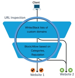
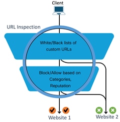
Workflow Summary:
● Checks if the detected URL is blacklisted or whitelisted. If the URL is blacklisted, the traffic is dropped, and if it is whitelisted, then the traffic is not subjected to further URL inspection.
● If the URL is not whitelisted or blacklisted, then it is further filtered based on the category and reputation score.
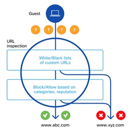
Detailed Workflow of URL Filtering: Cisco SD-WAN URL Filtering feature is implemented using the Snort engine and uses Snort preprocessors to extract URLs from web traffic.
When a request is made to access a website using a browser, at first, the browser makes a DNS request to get the IP address of the website.
Domain Based Filtering: If the domain within the DNS query matches the blacklisted domain name (such as .*customer.com), then either an error message is displayed on the web browser or the user is redirected to a different URL.
However, If the website’s domain name matches to one of the whitelisted patterns, then the client’s browser receives the IP address for the website and sends the HTTP(S) request to the website’s IP address. This whitelisted traffic is not subjected to further category or reputation based filtering, even if it is configured.
If the DNS query matches none of the configured whitelisted/blacklisted patterns names then the web browser receives the IP address of the website and sends the HTTP(s) request to the IP address. The HTTP/HTTP(s) traffic is inspected based on its category and reputation score. The traffic is either allowed or it is blocked and redirected to a block page or URL.
URL Based Filtering: If the URL in the HTTP/HTTP(s) request matches the blacklist, the request is blocked either by inline block page response or redirected to a different URL. If the URL in the HTTP/HTTP(s) request matches the whitelist, the traffic is allowed without further URL filtering inspection.
If List based filtering is not configured or the traffic does not match the configured whitelist/blacklist patterns, then the traffic is subjected to category and reputation based filtering. The traffic is either allowed or it is blocked and redirected to a block page or URL.
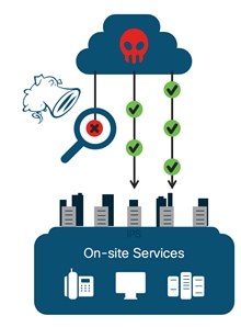
During the entire advanced threat lifecycle, malware typically traverses numerous Internet-connected devices before ultimately executing at the end-point to perform its malicious actions. Traditional anti-virus and file scanning solutions integrated into these network devices can be effective in blocking known malware but yet inadequate to analyze files that contain unknown malware. These point-in-time solutions also do not incorporate any visibility components to help customers understand all files traversing their network. By tracking all files - good, bad, and unknown – an advanced malware solution can reduce a customer’s time and costs during incident response investigation when malware slips past a strictly detection-based product.
The Cisco SD-WAN Advanced Malware Protection (AMP) integration equips routing and SD-WAN platforms to provide protection and visibility to cover all stages of the malware lifecycle:
● Before: Hardening the network border with firewall rules.
● During: Blocking malware based on file reputation and IPS signatures.
● After:
◦ Using file notifications to represent breaches that occurred;
◦ Retrospectively detecting malware and providing automatic reporting;
◦ Using advanced file analysis capabilities for detection and deeper insight into unknown files in a network.
The Cisco Advanced Malware Protection (AMP) is composed of the following processes:
File Reputation is the process of using a 256-bit Secure Hash Algorithm (SHA256) signature to compare the file against the Advanced Malware Protection (AMP) cloud server and access its threat intelligence information. The cloud server response can be clean, unknown, or malicious. If the response is unknown, and if file analysis is configured, then part of the response from the cloud includes the action to automatically submit the file for further analysis.
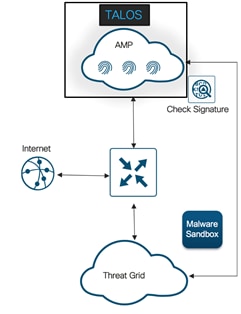
File Analysis is the process of submitting an unknown file to the Threat Grid (TG) cloud for detonation in a sandbox environment. During detonation, the sandbox captures artifacts and observes behaviors of the file, then gives the file an overall score of abnormal behaviors. Based on the observations and score, Threat Grid may change the threat response to Clean or Malicious. Threat Grid’s findings are reported back to the AMP cloud, so that all AMP customers will be protected against newly discovered malware.
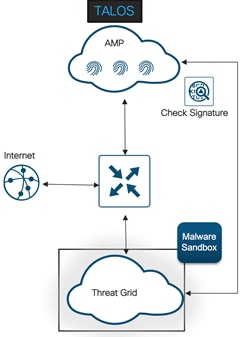
| Technical Tip |
| File analysis requires a separate Threat Grid account. For information about purchasing a Threat Grid account, contact your Cisco representative. |
A file's disposition is a categorization from the AMP cloud that determines what actions are taken on the file download. The three file dispositions include,
Clean: The file is known to be good.
Malicious: The file is known to be harmful.
Unknown: There is insufficient data to classify the file as clean or malicious.
Sometimes files will change disposition, based on new threat intelligence gained by the AMP cloud such as a change from unknown to malicious, clean to malicious, or malicious to clean. This re-classification will generate automatic retrospective notifications.
Design Considerations for Cisco SD-WAN Advanced Malware Protection Policy
Some of the design considerations while deploying SD-WAN AMP are explained below.
Supported Platform and Software
To enable Advanced Malware Protection (feature that leverages the UTD TAR file - Security Virtual Image), the platform must meet the minimum memory requirement of 8 GB flash memory and 8 GB DRAM.
To choose a platform that supports the AMP functionality with the minimum required memory, refer to the table for details.
Table 14. Supported Platforms – AMP
| Platform |
AMP |
| Cisco ISR4K Series (4461, 4451, 4431, 4351, 4331, 4321, 4221-X) |
Y |
| Cisco ISR1K Series and ISR1100X-4G/6G |
Y |
| Cisco ASR1K (1001-HX, 1002-HX, 1001-X, 1002-X) |
N/A |
| Cisco C8000v |
Y |
| Cisco Catalyst 8200L Series3 |
N/A |
| Cisco Catalyst 8200, 8300 Series (C8300-2N2S-4T2X/6T, C8300-1N1S-4T2X/6T) |
Y |
| Cisco Catalyst 8500 Series (C8500L-8S4X) |
Y |
| Cisco Catalyst 8500 Series (C8500-12X, C8500-12X4QC) |
N/A |
The number of cores are assigned based on the total number of cores available per device for the security app hosting profile.
| Technical Tip |
| To enable Threat Grid, please make sure you have procured the DNA subscription license. |
To enable AMP, make sure your WAN Edge device is running IOS XE SD-WAN version 16.10 or higher, along with a compatible (recommended) UTD engine code and control components running code 18.4 or higher.
We only support the UTD package that is released at the same time as the IOS-XE SD-WAN code. We call this the ‘Recommended Version’. For the recommended UTD code version, navigate to Monitor > Network > Real Time. Enter Security App Version Status under Catalyst SD-WAN Manager Device Options and find the Recommended Version. In the example, the Security Virtual Image for ISR4331 running 16.12.1d code is displayed.
In the above figure, the third column displays the Supported Regex pattern. The supported regex is the range of compatible virtual image versions for the router image. In this example, for a device running 16.12 IOS-XE SDWAN code, any virtual image from version 1.0.[0-9]+_SV(*)_XE16.12 onwards can be used. In this example, the [0-9]+ portion is the regex to denote that any SV image with version 1.0.X is compatible on the WAN Edge device.
Note: Regex means that the virtual image version has to end as _XE16.12. So basically, you can only use a 16.12 virtual image with a 16.12 IOS-XE SD-WAN code. The Snort engine version that comes after “SV” in the version string works as long as it ends as 16.12 for the router running 16.12 IOS-XE SD-WAN code.
Snort sensor and Catalyst SD-WAN Manager Virtual Image Repository
To enable Snort, it is required to download the Unified Threat Defense (UTD) Engine from software.cisco.com into the Catalyst SD-WAN Manager virtual image repository.
The virtual container images are downloaded from Catalyst SD-WAN Manager to the WAN Edge device to bring up the container with Snort enabled. The Snort sensor is deployed within the router as a virtual container service that monitors the traffic to detect anomalies based on the configured security policy (that includes signatures, statistics, protocol analysis, and so on) and sends log messages to the log server.
| Technical Tip |
| To bring up UTD services, WAN Edge device downloads the Recommended Version if present from the Catalyst SD-WAN Manager Repository. If not available, then the package that matches the Supported Regex is used. If no UTD packages that meet this regex pattern are found in the repository, then the UTD installation is aborted. |
Overview of SD-WAN Advanced Malware Protection Security Policy
Users can enable file reputation or file analysis or both within the security policy. For file analysis, users are provided with the list of file types for sandboxing based on the set of file types supported by the Threat Grid cloud and ISR platform.
AMP security policy functionality in IOS-XE SD-WAN WAN Edge device is deployed in a virtual service container leveraging existing IOX based Snort container infrastructure which currently also supports IPS and URL filtering services. This provides the flexibility to deploy and upgrade AMP software modules independently without impacting the Device.
Design consideration for File Reputation Policy and AMP Cloud
WAN Edge devices perform AMP disposition(reputation) lookups for files supported by Snort. Some of the file types supported on WAN Edge devices for AMP include, mov, flic, swf, exe, pdf, rtf, riff, zip, rar, msole2, mscab, mschm, bz, gz, arj, pdf, jpef, mp4, macho, macho unibin, pcap, mp3, pst, sit, wmf and dicm. It is the Snort file preprocessor that provides file type identification, file signature creation, and file capture capabilities. However, by default, file reputation does not have file type selection in the user interface.
Note:
● Currently, AMP solution is supported on the public cloud and the list of AMP cloud regions include NAM, EU and APJC. Choose the region based on the design.
● 10MB is the allowed file size limit for inspection using AMP and it works independent of the end device type.
● AMP is supported on clear text protocols such as HTTP, SMTP, IMAP, POP3, FTP, and SMB, and the supported file signature calculation is SHA256.
Design considerations for File Analysis Policy and Threat Grid (TG) Cloud
To submit files to the Threat Grid (TG) cloud, the Cisco SD-WAN WAN Edge device must have the TG API key. Ensure the API key used to register with the TG account on Catalyst SD-WAN Manager is from a TG user account with device-admin permissions. Within TG, you can set the file types that TG sends (not AMP) to the cloud for file analysis. The list of file types include pdf, ms-exe, new-office, rtf, mdb, mscab, msole2, wri, xlw, flv and swf.
| Technical Tip |
| To enable Threat Grid, please make sure you have the procured appropriate DNA subscription license. |
AMP and Threat Grid Registration
Independent configuration files are maintained in the container for AMP and Threat Grid registration along with the policy information. Registration information is received by the CLI manager module in the container. The CLI manager updates the configuration files with the registration information and restarts the corresponding modules for the configuration to take effect.
Subsequent, log messages for registration status is logged and sent to the Catalyst SD-WAN Manager server.
The alert log levels for AMP security policy for both file reputation and file analysis include critical, warning and info. It is ideal to stick to warning severity level for balance of load and information at production site. The Info severity level generates multiple notifications and can affect system performance and hence may not be ideal for real-time traffic.
Based on Fail-close/Fail-open option configured, last packet may or may not be held in the Snort session. The Fail-close option drops all the traffic when there is an engine failure. The Fail-open option allows for the flow of traffic bypassing all security features even at the time of an engine failure. The default option is Fail-open. Enable fail-close if security is the concern and select the option fail-open only if connectivity is the concern.
Design Target VPN for AMP Security Policy
When you create a policy for AMP feature, you must specify a target VPN. The target VPN can contain either a single VPN or a list of comma-separated VPNs.
When you enable these features on a single VPN, the corresponding policy is applied to both traffic from and to the VPN.
Security App Hosting Profile & Resources
While attaching the configured AMP policy within a device template, a sub-template titled container profile must be added. The container profile allows you to enable/disable NAT for your virtual services (AMP) and allocate the number of control plane cores for the virtual services.
Regarding the NAT functionality, it can be enabled if the virtual services go out to the Internet for manual signature updates on the WAN Edge device or if there is a need to send syslogs to an external syslog server that is not necessarily in the Data Center.
Regarding the Resource profile, by default the profile is the set to Default, for higher throughput set the profile to High.
General Operation of Cisco Advanced Malware Protection Security Feature
In AMP, known and unknown ransomware is detected by the WAN Edge router using AMP and the Threat Grid (TG) cloud. Follow the numbers in the figure below, along with the steps to understand the working of the AMP feature.
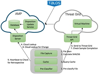
1. Snort file pre-processor on the device identifies file download.
2. The SHA256 of the file is calculated.
Local Cache Look up and Response
3. Cache lookup is done prior to making disposition requests to the AMP Cloud and the hashing technique is used to store and allow quick lookup of the SHA seen so far for the files from Snort.
The caching windows reduce unnecessary AMP disposition lookups for commonly seen files by returning disposition from the local AMP disposition cache instead of having to perform a lookup against the cloud.
Default TTL values based on disposition response is 2 hours.
Therefore, the SHA256 file is queried against a local cache system to see if the disposition is known and the cache Time To Live (TTL) is expired or not. As explained previously, cache lookup is done prior to making disposition requests to the AMP Cloud.
1. If the disposition is clean or unknown and the TTL is still valid, the file is allowed to pass through the system.
2. If the disposition is malicious and the TTL is still valid, the file is quarantined.
AMP Cloud Look up and Response
4. If the calculated SHA256 is looked up against the Advanced Malware Protection (AMP) cloud, then a disposition and return/response action is returned. Basically, Advanced Malware Protection cloud gives a response or disposition such as malicious, unknown or clean. Based on the disposition and return/response action the file is either allowed to pass through the system, blocked by the system or run through a pre-classification system.
5. The pre-classification system is made up of two steps,
1. File types the customer is willing to send to Threat Grid.
2. Validation that the file contains active content by a pre-classifier. For instance, if the response/disposition from AMP is unknown, then the WAN Edge checks for active contents.
Threat Grid Look Up and Response
6. If active content is found and the file type configuration allows for export, then the file is sent to the Threat Grid for file analysis. If the file is accepted for analysis, the response will have a sample ID and the file hash to identify the submission. If the rate limit for TG cloud requests is hit, the message will contain information about when to resubmit the file again.
Note: The requests are sent over a HTTPS connection established with the TG cloud server.
7. Six minutes after the file is submitted, Threat Grid is queried for sample check completion.
Queries AMP for retrospection
8. AMP cloud may receive change in dispositions for the file hashes queried earlier by the device.
Within every heartbeat interval (default heartbeat interval is 15 minutes), AMP is queried for any retrospective changes to dispositions.
Workflow of Cisco SD-WAN Advanced Malware Protection on WAN Edge device
The following steps explain the overall workflow of AMP security policy on IOS-XE SD-WAN WAN Edge devices:
● User enables AMP functionality on the devices using security policy workflow in Catalyst SD-WAN Manager. Configuration includes registration information, AMP file processing policies and reporting.
● WAN Edge device receives the configuration from Catalyst SD-WAN Manager and programs both data plane and service plane (Container) with the registration and policy information.
● AMP modules in the container register’s with AMP and/or Threat Grid cloud based on the configuration information.
● Data plane selectively redirects traffic matching the policies to the container for malware inspection and protection.
● Platform code in the container interfaces with Snort file preprocessor extracts the hash/file and submits the hash to Beaker* via API for malware detection verdict after checking in the local Cache.
● *Beaker is a common API framework that provides access to Intelligent Services, and an abstraction of the mechanisms required to support that access.
● Beaker may check in its cache for verdict and if not found will send query request to AMP cloud for verdict.
● Verdict will be received asynchronously. Based on Fail-close/open option configured, last packet may or may not be held in the Snort Session. If the Verdict is positive for Malware, alert will be generated and written to log file.
● If the response indicates unknown, then file is checked for pre-classification result and if found to be a supported file type with active content, it will be submitted to Threat Grid cloud for verdict using Cisco Sandbox API (CSA).
● Alerts and logs received by the Catalyst SD-WAN Manager is used to notify the admin for critical alerts. It is also used to display the malware trends in the network within network and device level dashboards.
The next section focuses on DNS/ Web-layer security with Umbrella Integration that enables you to gain simple, effective cloud security for your Cisco SD-WAN fabric.
Cisco SD-WAN DNS/Web-Layer Security
Cisco SD-WAN DNS/Web-layer security feature integrated in Catalyst SD-WAN Manager enables you to configure a WAN Edge device as a DNS forwarder to redirect DNS traffic to Cisco Umbrella resolvers or to a custom DNS server with a single configuration change.
Design Considerations for Cisco SD-WAN DNS/Web-layer Security
The upcoming sections focus on the definitions, concepts and design considerations around Cisco SD-WAN DNS/Web-layer security.
Supported Platforms and Software
Choose a platform that supports the Cisco SD-WAN DNS/Web-layer security functionality, with the minimum required memory. Refer to the table for details. The minimum required software version to deploy this feature on IOS-XE SD-WAN is 16.10 software image or later and on Catalyst SD-WAN Manager is 18.4 or later.
Table 15. Supported Platforms – Cisco SD-WAN DNS/Web-Layer Security
| Platform |
DNS/Web-Layer Security |
| Cisco ISR4K Series (4461, 4451, 4431, 4351, 4331, 4321, 4221-X) |
Y |
| Cisco ISR1K Series and ISR1100X-4G/6G |
Y |
| Cisco ASR1K (1001-HX, 1002-HX, 1001-X, 1002-X) |
Y |
| Cisco C8000v |
Y |
| Cisco Catalyst 8200L Series3 |
Y |
| Cisco Catalyst 8200, 8300 Series (C8300-2N2S-4T2X/6T, C8300-1N1S-4T2X/6T) |
Y |
| Cisco Catalyst 8500 Series (C8500L-8S4X) |
Y |
| Cisco Catalyst 8500 Series (C8500-12X, C8500-12X4QC) |
Y |
The configurable DNS Servers within the Cisco SD-WAN DNS/ Web-layer security policy include Cisco Umbrella and Custom DNS Servers.
Cisco Umbrella: Cisco Umbrella is a cloud-native platform that unifies firewall, secure web gateway, DNS/ Web-layer security, Cloud Access Security Broker (CASB), and threat intelligence solutions into a single platform to help businesses of all sizes secure their network.
The Cisco Umbrella Integration feature enables cloud-based security service to inspect the Domain Name System (DNS) query. The security administrator configures policies on the Cisco Umbrella portal to allow or deny traffic towards the fully qualified domain name (FQDN). The WAN Edge device acts as a DNS forwarder, and hence transparently intercepts DNS traffic, and forwards the DNS queries to the Cisco Umbrella portal.
| Technical Tip |
| To use the Cisco Umbrella Portal, please ensure you have the required DNA subscription Umbrella licenses. |
Note, DNS packets from SD-WAN enabled WAN Edge devices are redirected to Cisco Umbrella Anycast resolvers that include 208.67.222.222, 208.67.220.220, 2620:119:53::53 and 2620:119:35::35. The device uses the first default resolver IP address for all its redirection. When the WAN Edge device fails to receive a response for three consecutive DNS queries, the device automatically switches to a different resolver IP address.
Custom DNS Servers: Custom DNS Servers are remote or local DNS servers to which the DNS traffic is redirected.
Configure to redirect DNS traffic to Cisco Umbrella or to a custom DNS server based on your design requirement.
| Technical Tip |
| If an application or host uses an IP address directly instead of DNS to query domain names, policy enforcement is not applied. |
By configuring local domain bypass, split DNS functionality is added. This helps exclude internal DNS requests from being sent to Umbrella resolvers or external DNS Servers. A maximum of 64 local domains can be configured under bypass list, and the allowed domain name length is 100 characters. Some of the possible regex patterns/formats to enter domain lists on Catalyst SD-WAN Manager include .*cisco.com, .*.cisco.com.
Design Target VPN for DNS/ Web-layer Security
When you create a policy for DNS/Web-layer security feature, you can match all VPNs or specify a custom target VPN.
On WAN Edge devices, it is the Umbrella connector that intercepts DNS traffic and redirects it to Umbrella cloud for security inspection and policy application. The type A, AAAA, and TXT DNS queries are the only records that are redirected. Other types of query bypass the connector.
Note, the Umbrella Connector does not act on HTTP and HTTPS traffic or alter any web traffic.
When enabling Cisco SD-WAN DNS/Web-layer Security policy, note that in the advanced section of the policy the option DNSCrypt is enabled by default.
DNSCrypt is an encryption protocol used to authenticate communications between the WAN Edge device and the Umbrella Integration. When DNSCrypt gets triggered, a certificate is downloaded, validated, and parsed. A public-key is used to download the DNSCrypt certificate from the Umbrella Integration cloud. This value is preconfigured to B735:1140:206F:225D:3E2B:D822:D7FD:691E:A1C3:3CC8:D666:8D0C:BE04:BFAB:CA43:FB79 which is the public-key of Umbrella Integration Anycast servers. A shared secret key is then negotiated, which is used to encrypt the DNS queries. For every hour this certificate is automatically downloaded and verified for an upgrade, a new shared secret key is negotiated to encrypt the DNS queries.
| Technical Tip |
| When DNSCrypt is used, additional headers are added. Hence, Increasing the packet size of the DNS request to over 512 bytes. Ensure that these packets are allowed through the intermediary devices; otherwise, the response may not reach the intended recipients. |
Need to encrypt the DNS Packet
The DNS packet sent from the device to Umbrella Integration server must be encrypted if the packet contains information such as user IDs, internal network IP addresses, and so on. When the DNS response is sent back from the DNS server, a device decrypts the packet and forwards it to the host.
| Technical Tip |
| DNScrypt is only supported for Umbrella. |
Operation of Cisco SD-WAN DNS/Web-layer security with Umbrella
When a host initiates traffic and sends a DNS query, the Cisco Umbrella Connector in the WAN Edge device intercepts and inspects the DNS query.
If the DNS query is for a local domain (configured local domain bypass), it forwards the query without changing the DNS packet to the DNS server in the enterprise network. If it is for an external domain, it adds an Extended DNS (EDNS) record to the query and sends it to the Umbrella Resolver.
| Technical Tip |
| An EDNS record includes the device identifier information, organization ID and client IP. Based on this information, Cisco Umbrella Cloud applies different policies to the DNS query. |
When you send DNS request to Umbrella's DNS resolvers, you check to see if it's a malicious, non-malicious, suspicious site, or if it's blocked by a destination list or a content setting. The Cisco Umbrella Integration cloud, based on the policies configured on the Cisco umbrella portal and the reputation of the DNS Fully Qualified Domain Name (FQDN) may take one of the following actions:
● If the FQDN is found to be malicious or blocked by the customized enterprise security policy, then the IP address of the Umbrella cloud's blocked landing page is returned in the DNS response. This is called a blacked list action at Umbrella cloud.
● If the FQDN is found to be non-malicious, then the IP address of the content provider is returned in the DNS response. This is called a whitelist action at Umbrella Cloud.
● If the FQDN is suspicious, then the intelligent proxy unicast IP addresses are returned in the DNS response. This is referred to as grey list action at Umbrella Cloud.
However, note, the intelligent proxy option has to be enabled in the Umbrella dashboard, for the Umbrella resolver to return the intelligent proxy’s unicast IP addresses in its DNS response, when an attempt is made to access the domains in the grey list.
With the intelligent proxy enabled, if a site is considered potentially suspicious or could host malicious content, Umbrella resolver returns the intelligent proxy's IP address. The request to that domain is then routed through Cisco cloud-based secure gateway, and malicious content is found and stopped before it is sent. This provides the ability for Cisco Umbrella to intercept and proxy requests for malicious files embedded within the grey domain. Hence, allowing access to most known good sites without being proxied and only proxying those that pose a potential risk. Hence, with the use of an Intelligent proxy, we avoid the need to proxy requests to domains that are already known to be safe (e.g. a social media website).
| Technical Tip |
| If a client is connected to a web proxy, the DNS query does not pass through the WAN Edge device. In this case, the umbrella connector does not detect any DNS request and the connection to the web server bypasses any policy from the Umbrella portal. |
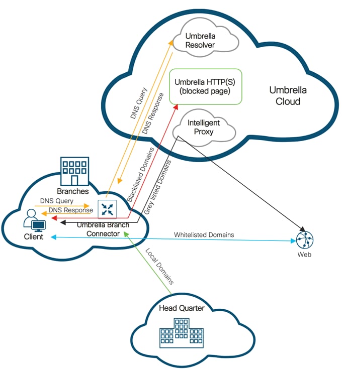
| Technical Tip |
| Cisco SD-WAN DNS/Web-layer security supports HTTPS decryption. |
When the DNS response is received, the device forwards the response back to the host. The host will extract the IP address from the response and send the HTTP / HTTPS requests to this IP.
FW Firewall
URLF URL Filtering
IPS Intrusion Prevention System
IDS Intrusion Detection System
URL Uniform Resource Locator
AMP Advanced Malware Protection
TG Threat Grid
APP Application
EDNS Extended Domain Name System
DNS Domain Name System
VPN Virtual Private Network
NAT Network Address Translation
LAN Local Area Network
WAN Wide Area Network
For comments and suggestions about this guide and related guides, join the discussion on Cisco Community at https://cs.co/en-cvds.