Cisco Catalyst SD-WAN Small Branch Design Case Study
Available Languages
Bias-Free Language
The documentation set for this product strives to use bias-free language. For the purposes of this documentation set, bias-free is defined as language that does not imply discrimination based on age, disability, gender, racial identity, ethnic identity, sexual orientation, socioeconomic status, and intersectionality. Exceptions may be present in the documentation due to language that is hardcoded in the user interfaces of the product software, language used based on RFP documentation, or language that is used by a referenced third-party product. Learn more about how Cisco is using Inclusive Language.
- US/Canada 800-553-2447
- Worldwide Support Phone Numbers
- All Tools
 Feedback
 Feedback
Cisco Catalyst SD-WAN Overview
Cisco Catalyst SD-WAN Design Methodology
SD-WAN Overlay Routing Across the Transports
Overlay IP Unicast Routing Design
Application-Aware Routing (AAR)
Appendix A: SD-WAN Centralized SD-WAN Controller Control Policy
Appendix B: WAN Edge Multicast Configurations
Appendix C: WAN Edge QoS Configuration
Appendix D: SD-WAN Controller AAR Data Policy Configuration
SD-WAN design case studies are deep-dives into the methodologies and technical solutions of how Cisco customers have leveraged SD-WAN use cases to achieve business outcomes. Although the companies covered in these case studies are fictitious, the designs, features, and configurations represent best practices and lessons learned from actual customer deployments across multiple industries.
Design case studies showcase the depth of Cisco’s coverage for the different categories of SD-WAN use cases as defined by the technological research firm Gartner, Inc, in the 2021 SD-WAN Edge Magic Quadrant (MQ) report. Design prototypes for each category have been built in Cisco Catalyst SD-WAN labs to validate the best practices and feature combinations covered in each case study. The categories include:
● Small Branch
● Global WAN
● Security Sensitive
● Cloud First
● Remote Worker
This design case study focuses on an SD-WAN deployment for an enterprise small branch. Gartner characterizes the SD-WAN small branch as a remote site supporting up to 10 people, where simplicity, cost consciousness, and flexibility of transport choices are key. Examples of the small branch category include gas stations, convenience stores, small banks, and fast-food restaurants.
This guide follows a fictitious company, American GasCo, through several planning and design phases and considerations they addressed during their journey to SD-WAN. Note that American GasCo is not a real customer and the network discussed within this document is not a real network, however, the use cases presented within this guide are based on actual customer deployments. The major topics of this guide include the following:
● SD-WAN high-level and low-level design methodology
● Enterprise considerations for Cisco cloud-hosted control component deployments
● SD-WAN underlay design for multiple types of WAN transports
● Small branch WAN Edge platform and topology considerations
● Cellular 4G/LTE branch deployment best practices
● Dual data center hub-and-spoke overlay routing
● Application-Aware Routing (AAR)
● Quality of Service (QoS)
● IP Multicast
This guide is not intended to be a step-by-step “how to” guide for deploying Cisco Catalyst SD-WAN, although enough details are provided for the reader to understand what features and configurations are required on the WAN Edge routers and control components. All use cases and feature combinations were prototyped in a Cisco lab environment using 20.6 SD-WAN Manager/17.6 IOS XE SD-WAN code versions. Supporting documentation can be found in the Cisco Catalyst SD-WAN Design Guide, which also references other existing SD-WAN documentation. Configurations for the devices in this test topology can be referenced at http://cs.co/SDWAN_CaseStudy_1.
Audience
The intended audience is for anyone who wants a better understanding of the Cisco Catalyst SD-WAN solution, especially network architects that need to understand the SD-WAN design best practices to make good design choices for their organization.
Cisco Catalyst SD-WAN Overview
| Tech Tip |
| Cisco SD-WAN has been rebranded to Cisco Catalyst SD-WAN. As part of this rebranding, the vManage name has been changed to SD-WAN Manager, the vSmart name has been changed to SD-WAN Controller, and the vBond name has been changed to SD-WAN Validator. Together, the vManage, vSmart, and vBond will be referred to as the SD-WAN control components or the SD-WAN control complex in this document. |
The Cisco Catalyst SD-WAN solution is comprised of separate orchestration, management, control, and data planes. The different major components that make up the solution are as follows:
● SD-WAN Validator (orchestration plane): The software component that performs initial authentication into the SD-WAN network and enables the communication between the SD-WAN control components and devices.
● SD-WAN Manager (management plane): The centralized network management system that provides a GUI interface to monitor, configure, and maintain the SD-WAN devices.
● SD-WAN Controller (control plane): The software component which is responsible for distributing routing, policy, and crypto key information to the WAN Edge routers.
● WAN Edge router (data plane): The hardware or software-based router that sits at a physical site or in the cloud and provides secure data plane connectivity between sites over one or more WAN transports.
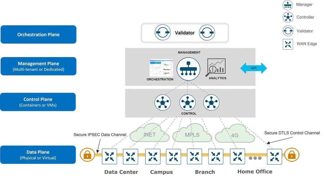
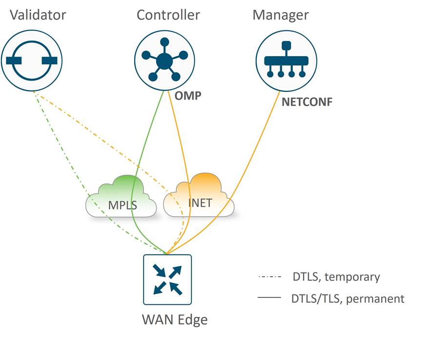
When attempting to join a Cisco Catalyst SD-WAN overlay network, the WAN Edge router first authenticates with the SD-WAN Validator by initiating temporary Datagram Transport Layer Security (DTLS) control connections over each WAN transport. Once authenticated, the WAN Edge router then forms a permanent DTLS or Transport Layer Security (TLS) control connection with the SD-WAN Manager NMS over a single WAN transport, and initiates DTLS or TLS connections to two SD-WAN Controllers by default over all transports. After being onboarded to the SD-WAN overlay by the control components, the WAN Edge router joins the fabric by establishing IPsec (default) or GRE tunnels to other WAN Edge routers. WAN Edge routers initiate continuous Bidirectional Forwarding Detection (BFD) probes over each of these tunnels to ensure peer liveness, while also measuring the loss, latency and jitter associated with each WAN transport. Refer to the Cisco Catalyst SD-WAN Design Guide for more detailed information regarding the interworking of the Cisco Catalyst SD-WAN architecture.
Cisco Catalyst SD-WAN Design Methodology
Cisco recommends a top-down approach be taken with SD-WAN designs to ensure the platforms, use cases and features chosen will support the project goals and business objectives of the organization. American GasCo followed a design methodology that included specific steps that are summarized below:
● Network goals and objectives: The network goals and objectives and the purpose for implementing SD-WAN is captured.
● Current requirements and problem areas: In this phase, current applications in the network and their latency and loss tolerances are identified, along with the traffic patterns, current hardware, software, and transports and their current utilization. In addition, the network performance should be reviewed to identify any problem areas.
● New WAN and site standards: Once an audit has been completed and the SD-WAN use cases that will be implemented are identified, physical and logical topology standards can be developed for how the WAN Edge routers connect to the LAN and WAN infrastructure. Different sets of standards are often necessary when an organization has remote sites with unique business requirements, or when sites are classified by the numbers of users at a site.
Site standards should also take into consideration any future SD-WAN use cases and features that are expected to be deployed, such as direct internet access, cloud networking, on-premise security, multicast routing, or IPv6. These features may have an impact on traffic load, flow patterns, and other factors that will drive decisions on bandwidth, redundancy, and WAN Edge platform selection.
● High-Level Design (HLD): A high-level design can then be developed. In the high-level design, decisions are made around the key elements of the SD-WAN deployment, such as budget allocation, project scope, and orders for circuits and hardware. It includes the necessary information needed to determine the platform choices, such as the features and circuits required, and bandwidth and number of IPsec tunnels per device for each site required for the design. The following topics were addressed in the high-level design for American GasCo:
◦ Planned use cases and features: The SD-WAN use cases and features to be implemented are determined, such as application visibility, VPN segmentation, Application-Aware Routing (AAR), Quality of Service (QoS), Forward Error Correction (FEC), cloud-based access, on-premise security, multicast, etc.
◦ SD-WAN Manager and WAN Edge router code version selection: There is a balance between choosing a code version for support of all desired features with choosing a version which has had sufficient field time for stability reasons. The code version used in the deployment can influence the design based on what features are supported as well as the control plane scale supported. Newer platforms for the SD-WAN deployment may offer less code choice flexibility, as these devices may only be supported by newer code versions.
◦ WAN transport circuits: The WAN transports that will be used during the deployment are chosen.
◦ Control component deployment: The control component deployment model should be chosen. For on-premise deployments, enough information needs to be gathered to determine the number of control components, the server requirements for them, and how they will be distributed in the network.
◦ VPN segmentation: Identify any VPN segmentation in the network. This might be segmentation for separating traffic between lines of business, or traffic types requiring different topologies, such as full-mesh or spoke-to-spoke connectivity.
◦ Transport color scheme: Transport colors are the means in which the SD-WAN infrastructure associates overlay tunnels with underlying WAN transport circuits. Transport colors are configured as labels in the tunnel configurations of the branch and data center WAN Edge routers and can be leveraged by control and data policy logic. Since the number of transport circuits at a Data Center is often more than any branch, decisions need to be made whether every unique transport should warrant a unique tunnel color, or whether certain transports can be aggregated by the underlay routing infrastructure and treated as the same color. This information will help calculate the IPsec tunnels required in the network.
◦ SD-WAN overlay tunnels: Based on traffic flows during the audit and future traffic requirements, determine what topology is required per VPN (full mesh, hub-and-spoke, partial mesh, etc.), and based on the transport color scheme, calculate the number of tunnels required per device.
◦ WAN Edge router platform selections: Determine the hardware devices (if needed) that can accommodate the new site requirements.
● Low-Level Design (LLD): The low-level design can be worked on in parallel with the high-level design. In the low-level design, specifics about the configurations and policies and other parts of the implementation are developed and validated when necessary. The following topics were addressed in the low-level design for American GasCo:
◦ Control component deployment: For the Cisco-managed, cloud-hosted control components, the LLD should address initial onboarding details of the control components (virtual machine sizing, certificate installation) and reachability to remote site WAN Edge routers and customer NMS servers, when required.
◦ Branch design: Detailed site profiles with new platform and connectivity standards should be developed. Specific transports used to provide redundancy and SLAs necessary for the applications should be determined. If LTE is utilized, considerations should be taken to make the most efficient use of the bandwidth.
◦ Data center design: This topic addresses the connectivity and routing between the WAN Edge routers and the data center WAN transports and LAN backbone.
◦ SD-WAN underlay design: This topic addresses the connectivity and IP routing design for the end-to-end path between WAN Edge router tunnel endpoints.
◦ Firewall considerations: The NAT types for the various sites and what ports need to be opened on the firewalls for SD-WAN required connectivity should be determined.
◦ SD-WAN overlay design: Various aspects of the overlay design should be determined, including the site-ID scheme, control policy, cellular tunnel optimizations, VPN segmentation details, IP unicast and multicast routing, Quality of Service (QoS), and Application-Aware Routing (AAR).
Company Background
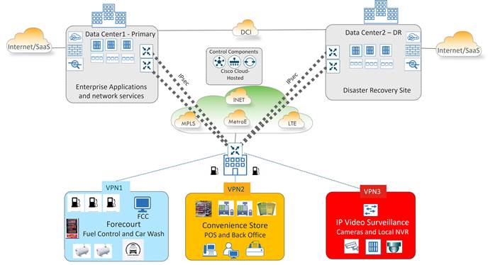
American GasCo corporation owns and operates approximately 500 gas station convenience stores in the southeastern region of the US. In addition to selling fuel and car wash services, the company retails food, beverages, tobacco products, periodicals, lottery tickets, and other convenience items. The headquarters location in Atlanta, GA includes the company's primary data center that hosts enterprise services, including outbound access to the Internet for the stores. A backup data center in a colocation facility in Raleigh, NC serves as a disaster recovery site, providing business continuity in the event of a catastrophic outage. Application data stores are replicated nightly from the primary DC to the backup DC over a high bandwidth data center interconnect (DCI) circuit.
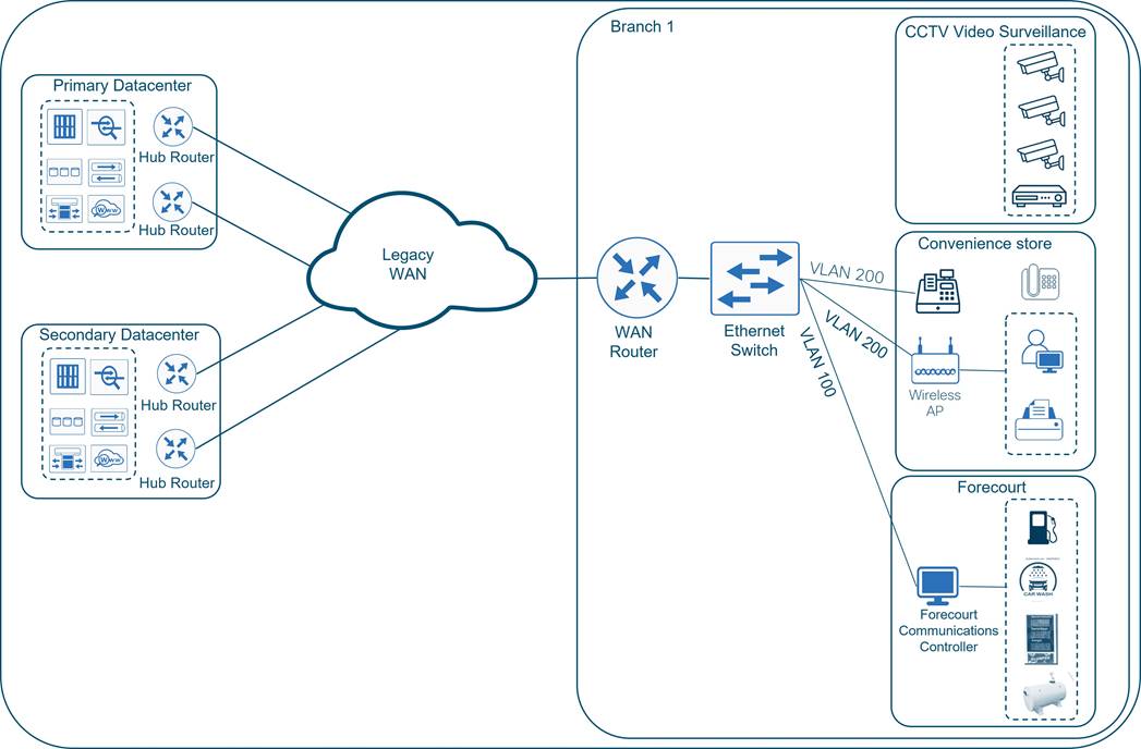
The legacy Wide Area Network (WAN) was built with Cisco routed technologies to securely connect gas station devices and convenience store users to enterprise applications in the data centers and SaaS applications on the Internet. This included a classic MPLS/VPN network and DMVPN fabric of IPsec tunnels overlaid on top of the Internet service provider transports that extended between a remote site router and pairs of hub routers in each of the data centers. A single Cisco ethernet switch partitioned into VLANs was installed at the branch to connect remote site operators and devices. There are three fundamental services for the stations, which include:
● Forecourt Controller (FCC) system that controls the fuel dispensers, storage tank controllers, outdoor payment terminals, price poles, and automated car wash devices. American GasCo uses an FCC system with an embedded processor that is reachable over a web server interface for remote monitoring and maintenance.
● Convenience store point-of-sales terminals, back-office computers, and printers.
● Legacy CCTV video surveillance system with in-store monitors and DVR for security monitoring of the convenience store and forecourt areas. It is a self-contained analog system that does not use the IP WAN infrastructure.
Network Modernization Initiative
American GasCo migrated their network to Cisco Catalyst SD-WAN as part of a gas station modernization program to support multiple IT projects to include:
● Office automation and refresh of back-office computers, fax machines, and printers
● New Point-of-Service (POS) systems for the gas pumps and convenience stores
● Upgraded audio, video, and digital signage systems in the stores and forecourt areas
● Replacement of in-store, CCTV security systems with a next-generation IP video surveillance system that includes remote-monitoring and remote storage of video activity
● Replacement of landline telephones with Cisco IP telephony
● Network equipment refresh to replace end-of-life routers, switches, and wireless access points.
All the new initiatives were designed to either increase revenue or decrease store operating costs by improving efficiency. American GasCo understood that WAN availability would be more critical than ever, and that the new IP video surveillance system (in particular) would dramatically increase WAN traffic.
To meet the WAN transport redundancy and capacity demands while avoiding the high cost of provisioning additional MPLS circuits, American GasCo sought to utilize any IP-capable transport available at a store. This included an increased dependence on broadband Internet service delivered through cable or DSL and the introduction of business class Internet and cellular 4G/LTE as additional public WAN transport methods. Private, point-to-point circuits, and Metro Ethernet services were also planned to be introduced at store locations where access was available.
American GasCo selected Cisco Catalyst SD-WAN as the replacement for the legacy architecture largely due the flexibility of the WAN Edge routers in terms of transport connectivity, as well as the application visibility and control that would optimize transport selection for the different applications.
SD-WAN Migration Methodology
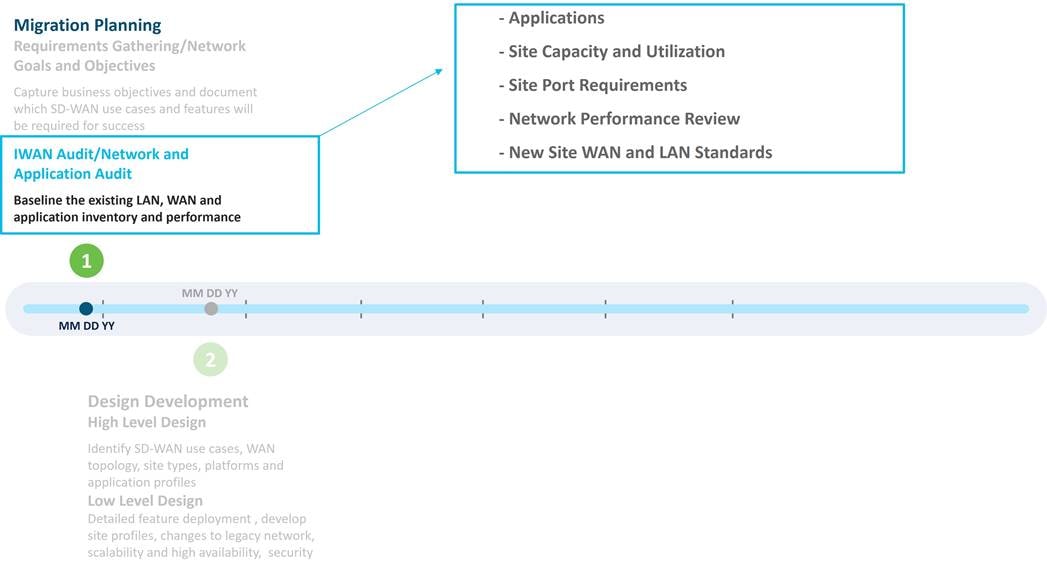
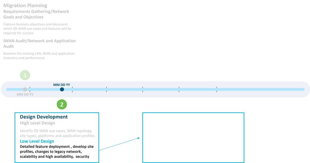
American GasCo followed Cisco’s recommended methodology for SD-WAN design and migration, following the IWAN to Cisco SD-WAN Migration Guide. A summary of the workstreams from this guide is shown below:
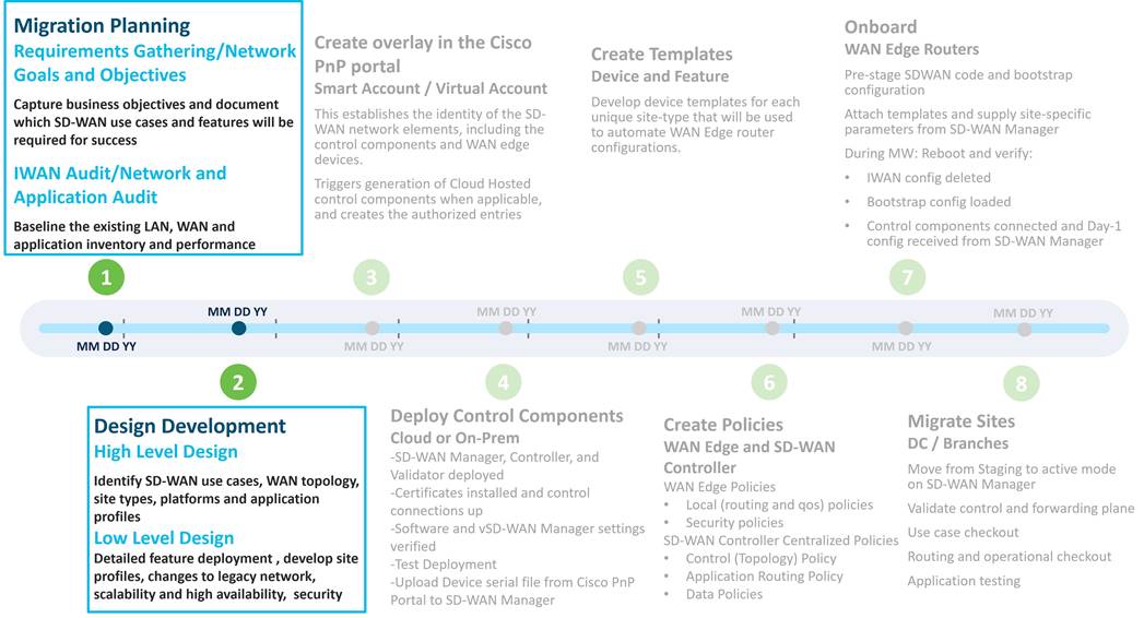
American GasCo spent considerable time during the planning and design phases to ensure that the proper platforms, use cases, and features could be thoroughly evaluated. Business requirements were documented, and a baseline of the existing network was taken to understand current LAN/WAN capacity and pain points. This was used as input into the high and low-level design documents that were developed and highlighted in this guide.
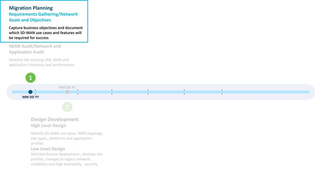
The first step in an SD-WAN design is to capture network goals and objectives and then identify the use cases that will be used to satisfy them. These will drive decisions about platform hardware and code selection, transport types, features, configurations, and policies that will be addressed by the design. The following table captures American GasCo's network objectives and SD-WAN use cases planned for deployment.
Table 1. Network Objectives and SD-WAN Use Cases for American GasCo
| SD-WAN Use Cases |
|
| Increase network availability |
Ensure every site has two or more WAN transports capable of handling the full traffic load Leverage cellular at critical sites as a last resort path in case of complete fiber cut of ethernet transports |
| Improve application performance |
Increase WAN bandwidth at remote sites to reduce congestion Leverage advanced QoS features such as per-tunnel and adaptive QoS to prioritize critical applications Utilize performance monitoring and application-aware routing. Critical applications are routed to the best-performing links |
| Reduce WAN carrier costs |
Leverage Internet and private circuits over MPLS when more bandwidth is required at a site Use application-aware routing and data policies to steer low priority traffic over less expensive links |
| Improve WAN security |
Segment devices, users, and cameras into different VPNs Leverage zero-trust onboarding with certificate-based identity |
| Simplify network operations |
Leverage centralized provisioning, monitoring, and troubleshooting with the SD-WAN Manager Utilize GUI-driven templates and policies for standardized configurations |
Direct Internet Access, SASE/Secure Internet Gateway, and Cloud Networking were all use cases interesting to American GasCo, but it was decided that phase 1 would be limited to deploying a basic SD-WAN secure automated WAN infrastructure. This would allow them to become familiar with operating an SD-WAN overlay and set the foundation for the advanced use cases that would be implemented in future phases.
In this phase, a baseline audit of the applications, site capacity, utilization, and site port requirements was performed, followed by a review of Sev1 tickets and availability reports. New site LAN and WAN standards were then derived to help drive decisions around which platforms would be ordered and how much bandwidth would be necessary for the new SD-WAN deployment.
A telecommunications outsourcing company was contracted by American GasCo to lead the audit and analyze the existing WAN transport performance, capacity, and pricing. Based on the results, the consultant assisted with planning WAN capacity for each site and helped establish the new network requirements. Once completed, the consultant helped evaluate, select, and negotiate contracts with the service providers that would provide new circuits for sites that required additional bandwidth or redundancy, which included alternative bandwidth solutions, such as private Ethernet (P2P, Metro Ethernet), business Internet, and cellular 4G/LTE.
Applications
As a first step, the consultant worked with American GasCo engineers to analyze the current applications and traffic flows. The American GasCo legacy routers were exporting IPFIX and NBAR application data to NetFlow collectors which allowed them to identify traffic patterns of the various applications. The table below represents the top applications in use at the American GasCo store locations.
Table 2. American GasCo Application Audit
| Application |
Traffic Patterns |
Business Relevance |
| Forecourt controller |
Store to forecourt servers in DC |
Relevant |
| Convenience Store Point of Sales (POS) |
Store to POS servers in DC |
Relevant |
| |
Store to email server in DC |
Relevant |
| SNMP, Syslog, SSH |
Store to servers in DC |
Relevant |
| Facebook, Instagram, Twitter |
Store to Internet exit at DC |
Irrelevant |
| HTTP/HTTPS |
Store to Internet exit at DC |
Unknown |
| YouTube |
Store to Internet exit at DC |
Unknown |
| Wireless CAPWAP tunnels |
Store to Wireless LAN controller at DC |
Relevant |
Site Capacity and Utilization
WAN circuit capacity and utilization was measured at each store over a period of several weeks in order to understand the traffic load of the existing applications. Stores were classified into site types based on size and bandwidth requirements as shown in the table below.
Table 3. American GasCo Site Type Inventory and WAN Capacity
| Site Type |
Description |
Number of Sites |
Number of Routers per Site |
WAN Transport Circuits |
WAN Circuit Capacity |
Circuits Exceeding 70% BW Utilization |
| Type 1 |
Small-size filling stations with outdoor payment terminals, some with a single employee selling convenience items from within a secured enclosure |
147 |
1 |
1x broadband Internet circuit |
5 Mbps |
50 |
| Type 2 |
Medium-size filling stations with outdoor payment terminals and a small indoor convenience store |
221 |
1 |
1x broadband Internet circuit |
10 Mbps |
70 |
| Type 3 |
Large-size filling stations with outdoor payment terminals and indoor convenience store with limited food-to-go |
120 |
1 |
1x MPLS and 1x broadband Internet circuits |
20 Mbps |
60 |
| Type 4 |
Rest stop with outdoor payment terminals and full-service store with an indoor restaurant and wi-fi for guests |
12 |
1 |
2x MPLS circuits |
50 Mbps |
10 |
| Primary data center |
Data center server farm to host various applications and Internet access via DC Internet exit. Large on-premise office in the primary DC (HQ – Atlanta) |
1 |
2 |
2x MPLS and 2x broadband Internet circuits (1 each per router) |
2x400 Mbps |
1 |
Site Port Requirements
The consultant then worked with the store owners to obtain a count of active connections on the Ethernet switches at each site to help determine whether American GasCo could consolidate the switching functions into a WAN Edge router with a Layer 2 switch module. The switch port audit included a count of ports providing power over ethernet (PoE) capabilities to devices such as Wifi access points or IP phones that may have been installed at certain stores. The data center sites were not included in this audit since American GasCo had a traditional DC design with distinct core, distribution, and access layer devices.
During the audit it was discovered a mix of Fast Ethernet (100 Mbps) and Gigabit Ethernet (1000 Mbps) connections on the switches, but no Power over Ethernet (PoE) capabilities.
Table 4. American GasCo Store Ethernet Port Counts
| Site Type |
Ethernet LAN ports in Use |
| Type 1 |
1-2 |
| Type 2 |
1-4 |
| Type 3 |
3-5 |
| Type 4 |
4-8 |
Network Performance Review
Finally, a review of the help-desk tickets and service provider outage reports were conducted to gain an understanding of the overall network stability and performance at the different sites. The following conclusions were drawn:
● Most major outages were due to circuit instabilities, primarily at sites with single WAN connections.
● Router crashes or failures were infrequent and not considered to be a factor.
● Network performance slowdowns were common at the type 1 and type 2 sites having single broadband Internet circuits, and further examination of the interface queues indicated a large number of packet drops, suggesting network congestion to be the cause.
● It was noted that type 3 sites with dual WAN connections were sending and receiving traffic only on the MPLS link, leaving the Internet link largely unused. This was attributed to an active/backup routing design that preferred the BGP routes learned from the MPLS providers over the EIGRP routes learned over the DMVPN tunnels on the Internet transports.
New Site Type WAN and LAN Standards
Once an existing network audit was performed, future requirements were considered based on the modernization projects along with future gas station growth. First, the traffic patterns and business relevance of the future applications were captured:
Table 5. Future Applications
| Application |
Traffic Patterns |
Business Relevance |
| IP Video Surveillance |
Store to storage and monitoring systems in DC |
Relevant |
| IP Telephony |
Store to CCM/SIP servers in DC (VoIP signaling) Store to Data center NOC IP telephony (VoIP bearer) Store to off-net destinations via VoIP gateway in DC (VoIP bearer) |
Relevant |
| Office 365 |
Store to Internet SaaS sites via DC Internet exit |
Relevant |
An estimate of the additional bandwidth required to support the new IP video surveillance, Telephony, Office 365, and other applications was added to the site baseline to create new WAN standards for each branch. Additional Ethernet and PoE port requirements were determined based on the new applications to create new LAN standards. Bandwidth for the data center was calculated based on the existing audit of applications and the additional load expected from the new applications. N+1 bandwidth redundancy was planned for the data center, so that each WAN Edge router could support the full site bandwidth in the event that either Edge router lost power or became unavailable for some other reason. The new site type WAN and LAN standards would be the basis for hardware platform selections and could also be used by the telecommunications service providers for pricing estimates.
Table 6. American GasCo New Site Type WAN and LAN Standards
| Site Type |
New Site Bandwidth Specification |
New WAN Transport Standard |
New Ethernet LAN port specification |
PoE / PoE+ ports required? |
| Type 1 |
Up to 50 Mbps |
Single Ethernet WAN transport (Metro Ethernet/MPLS/Broadband Internet) + active “always-on” LTE |
Up to 4 |
Up to 2 PoE |
| Type 2 |
Up to 150 Mbps |
Dual Ethernet WAN transports (Metro Ethernet/MPLS + Broadband Internet) |
Up to 8 |
Up to 2 PoE |
| Type 3 |
Up to 300 Mbps |
Dual Ethernet WAN transports (Metro Ethernet/MPLS/Business Internet + Broadband Internet) with LTE for backup |
Up to 8 |
Up to 4 PoE |
| Type 4 |
Up to 500 Mbps |
Dual Ethernet WAN transports (Metro Ethernet/MPLS + Business Internet) with LTE for backup |
Up to 16 |
Up to 4 PoE |
| Data center |
Up to 2x10 Gbps |
Multiple incoming WAN transports (Metro Ethernet + MPLS + Business Internet) |
N/A |
N/A |
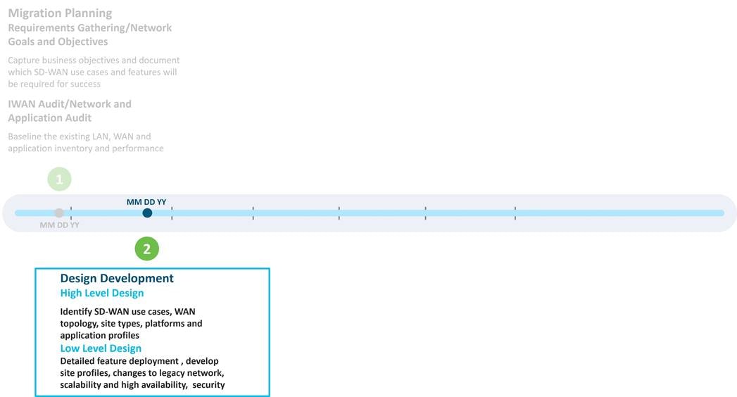
SD-WAN design development often includes creation of High-Level Design (HLD) and Low-Level Design (LLD) deliverables during different phases of the project. The HLD is crucial at the start of a project, where budget is allocated and orders for hardware, software, licenses, control components, WAN transport circuits, and tools must be placed. Some of these items may take months of lead time, particularly when site construction is required to bring in new transports or manufacturing backlogs delay hardware. The SD-WAN high-level design should be lean, easy to read, and clearly document the project scope. The HLD should include the number of sites, number of WAN Edge routers per site, number of transports, planned use cases and features, platform selection, and control component deployment model. The low-level design includes all the specifics of how the device configurations and policies will be implemented with an emphasis on connectivity, fabric and site routing, and advanced features that enhance the application experience. The low-level design is where migration considerations, site onboarding, integration with management tools and operational processes is addressed.
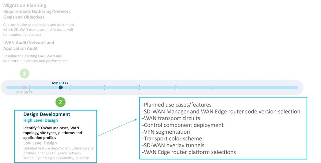
A high-level design was developed by American GasCo to document key decisions around the main elements of the SD-WAN deployment, which includes the following topics:
● Planned use cases/features: the use cases and features that will be implemented in the first phase of the SD-WAN deployment
● SD-WAN Manager and WAN Edge router code version selection: the code version targeted for the SD-WAN devices during the initial SD-WAN deployment
● WAN transport circuits: which WAN transport circuits will be used in the deployment
● Control component deployment: which control component deployment model will be used
● VPN segmentation: what VPNs will be used in the new design
● Transport color scheme: what colors are assigned to the transports in the SD-WAN overlay
● SD-WAN overlay tunnels: calculating the SD-WAN tunnel requirements
● WAN Edge router platform selections: what SD-WAN router platforms are chosen for the different site types in the deployment
Planned Use Cases/Features
For American GasCo, the SD-WAN phase 1 deployment would include the following use cases and features:
● Secure automated WAN
◦ Introduction of Business Internet and Metro Ethernet WAN transport circuits
◦ LTE as an “always-on” circuit at some site types and a circuit of last resort at others.
◦ Hub-and-spoke SD-WAN tunnel topology
◦ VPN segmentation in the stores and data centers
◦ IP Multicast
● Application performance optimization
◦ Application visibility
◦ Application-Aware Routing
◦ Quality of Service (QoS)
SD-WAN Manager and WAN Edge Router Code Version Selection
Based on the planned use cases, American GasCo needed to choose a SD-WAN Manager and WAN Edge router code version to deploy. This is defined in the high-level design because the code selection may affect what is supported from a control plane scale perspective and may change the design depending on the features and use cases that are supported.
There are several documentation references to use for choosing the most appropriate software:
● The software release notes are useful for checking on supported features and caveats.
● The SD-WAN device compatibility sheet shows what code version supports what hardware platforms.
● The control components compatibility matrix demonstrates what control components code versions are compatible with which WAN Edge router versions.
● The recommended SD-WAN software versions for control components and WAN Edge routers guide provides guidance to customers on the Cisco Catalyst SD-WAN software lifecycle to assist in code choices. The general idea is to run a release marked as a recommended release under the software downloads page, but if features are needed in higher versions of code, try to stick to extended maintenance releases which have a longer support lifetime. Examples include 20.6/17.6, 20.9/17.9, and 20.12/17.12 (control components image version/IOS XE SD-WAN image version).
American GasCo chose 20.6.3 for the control components and 17.6.3a for the IOS XE SD-WAN routers, since it is an extended maintenance release image, and it is currently on its 3rd maintenance release. By the time American GasCo would be ready to go into production, the code would have had over a year’s worth of field exposure. American GasCo was comfortable with this choice.
20.6.3/17.6.3a also supports the platforms American GasCo would be interested in along with the basic features they are interested in deploying. American GasCo is also interested in features they could deploy in the future which are introduced in the 20.6/17.6 release:
● Quick Connect Workflow for onboarding Cisco IOS XE SD-WAN devices
● Cisco Catalyst SD-WAN EtherChannel support on the service-side VPNs (for the data center hub routers)
● Per-VPN QoS, where you can configure a QoS policy to limit the bandwidth that can be used by traffic belonging to a VPN or group of VPNs
WAN Transport Circuits
WAN performance and overall user experience is highly dependent on the last mile circuit that connects it to end users and devices in the business location. Cisco Catalyst SD-WAN features such as Application-Aware Routing (AAR), Forward Error Correction (FEC) and TCP Optimization are able to address transient impairments on the end-to-end WAN path but are no substitute for stable last mile circuits provisioned with adequate bandwidth to handle the traffic loads that occur during peak periods of usage. In other words, having a robust and stable underlay with plenty of bandwidth is of the utmost importance.
As a result of the network audit, it was determined that a lack of circuit redundancy and bandwidth congestion on the existing transport circuits were the major sources of issues on the WAN. American GasCo contracted with several new WAN service providers to provide new transports to augment the site MPLS and broadband Internet circuits that provided transport for the legacy WAN. In addition to MPLS and broadband Internet, they decided to augment with the following transport types:
● Dedicated Internet circuits: Business-class Internet circuits with SLA guarantees for upload and download symmetrical bandwidth. Provisioned at data centers and larger remote sites as a substitute for public, broadband Internet circuits with no bandwidth SLA.
● Metro Ethernet: Ethernet Private Line and Virtual Private Line services. Deployed at data centers and remote sites located in metropolitan areas where service is available as higher bandwidth/lower cost alternative to MPLS.
● Cellular 4G/LTE: Used at small locations having no access to leased circuits or as a secondary, always-on connection. Also used at larger sites as a backup circuit to provide business continuity during failure of leased circuits.
Control Component Deployment
The SD-WAN Manager, SD-WAN Controller, and SD-WAN Validator are deployed as virtual machines on server hardware located on-premise or in a cloud service provider. The high-level design should address the number of control component instances required for scale and redundancy, the amount of compute and storage needed for each VM, where the control components should be hosted, and who should be responsible for deployment and operations. There are three common control component deployment models:
● Cisco cloud-hosted: In this model, control components are deployed in AWS or Azure. Cisco takes care of provisioning the control components and meeting requirements for scale and redundancy. Cisco is responsible for backups/snapshots and disaster recovery and will scale out the control component deployment as the network grows. The customer is given access to the SD-WAN Manager for creating configuration templates and control and data polices for their devices.
● On-premise: In this model, control components are deployed on the customer premises in a data center or regional hub, or in a private/public cloud or co-location facility. The customer is responsible for the server hardware, provisioning the control components, and all maintenance and monitoring activities.
● Managed Service Provider (MSP): In this model, the control components are hosted by the service provider in a private or public cloud and the provider is responsible for backups and disaster recovery.
American GasCo evaluated the pros and cons of each of the three deployment models for control components.
Table 7. Pros and Cons for the Different Control Component Deployment Models
| Pros |
Cons |
|
| Cisco cloud-hosted control components |
Rapid deployment of control components in AWS or Azure by Cisco Cloud operations Cisco responsible for deployment, monitoring, backup and restore functions of the control component infrastructure Cisco proactively monitors capacity and can expand resources quickly as the network grows |
Cisco Cloud Ops is not responsible for monitoring the Cisco Catalyst SD-WAN overlay services |
| On-premise in a private cloud or data center owned by the organization |
Customer has complete control of the physical servers and storage environments Sometimes required by customers with strict security policies that prohibit cloud deployments of network infrastructure |
Time to deploy typically longer than cloud-hosted Cisco does not have visibility to control components for monitoring and troubleshooting Must plan carefully for growth upfront, as it is more difficult to upgrade physical resources later as the network grows |
| Managed Service Provider (MSP) or partner-hosted cloud |
Widely varies depending on the specific MSP’s control components hosting methods and operations |
Widely varies depending on the specific MSP’s control components hosting methods and operations Additional costs may be involved compared to Cisco cloud-hosted option |
American GasCo chose the Cisco CloudOps-managed, cloud-hosted option to accelerate their deployment and avoid the operational burden of ongoing monitoring and maintenance of the control components hardware and infrastructure software.
VPN Segmentation
American GasCo security policy mandates video surveillance traffic be kept separate from convenience store and forecourt point-of-sales applications. End-to-end VPN segmentation within the store and across the SD-WAN to the data center was planned to completely isolate each of the following VPNs:
Table 8. American GasCo VPN Definitions
| VPN |
Purpose |
| VPN 1 |
Forecourt applications |
| VPN 2 |
Convenience store applications |
| VPN 3 |
Video surveillance |
Transport Color Scheme
SD-WAN color attributes are the means in which the SD-WAN infrastructure maps the overlay tunnels to the underlying transport circuits that are terminated on WAN Edge router TLOC interfaces. Color attributes are a key component of centralized control policies that dictate the degree of tunnel meshing and should be worked out in the high-level design.
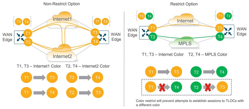
Color Restrict
By default, a WAN Edge router will attempt to create tunnels to every remote TLOC it discovers from OMP during initial onboarding. Tunnel setup to every remote TLOC is attempted over each local WAN transport, including TLOCs that belong to other transports marked with different colors. This is useful when using a public network underlay comprised of different ISPs, but often undesirable when there is a mix of public and private transports with no interconnection points.
To prevent this behavior, a restrict keyword can be specified when defining the tunnel characteristics. This prevents attempts to establish BFD sessions to TLOCs with different colors and is commonly used to limit the number of tunnels and associated overhead on the WAN transport circuits.
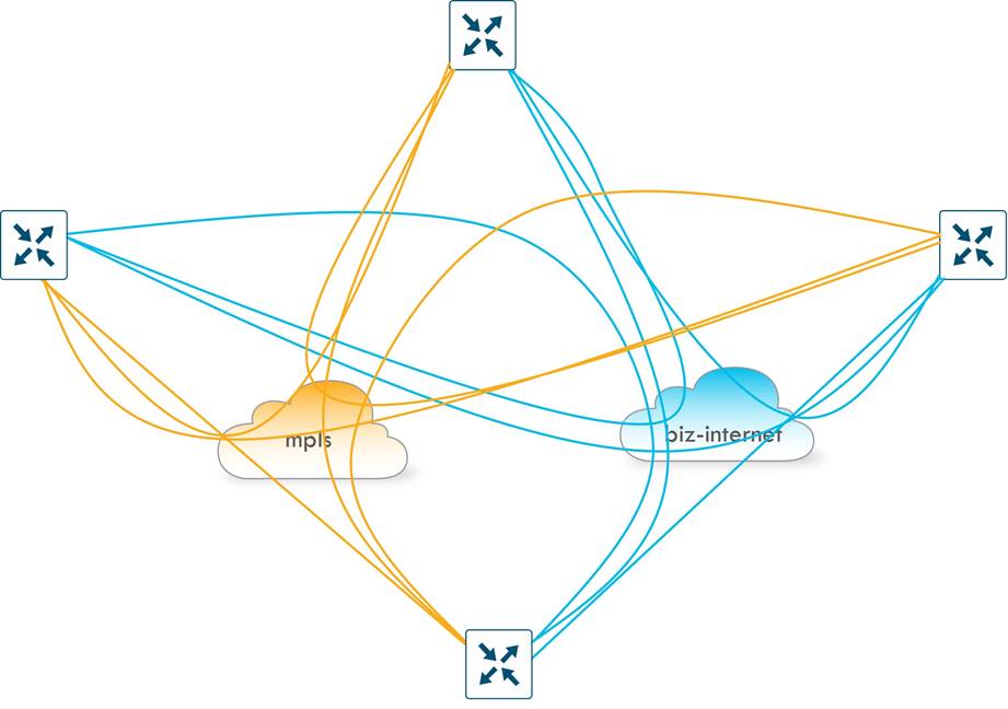
| Without any tunnel restriction in the network, BFD sessions and secure IPsec tunnels are formed between all TLOCs. This can substantially increase the number of tunnels in the network, which can be a factor in the ability to scale the network depending on the WAN Edge platforms used. It can give you more paths between TLOCs which could translate into more available paths that meet SLA thresholds when out-of-threshold events occur, but at the expense of more tunnels to manage and troubleshoot if problems do occur. |
The following diagram shows the non-restrict (default) option as compared to the restrict option. The non-restrict option results in twice as many tunnels between the two WAN Edge routers with two transports involved as shown in the diagram below.
American GasCo Transport Color Scheme
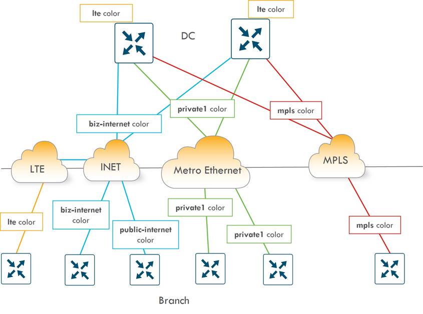
A transport color scheme was developed for American GasCo. On the branch side, three distinct transport colors (public-internet, biz-internet, and lte) were specified for broadband Internet, business class Internet, and cellular 4G/LTE transports, respectively. The private1 color was specified for point-to-point Ethernet or Metro Ethernet transports, and the mpls color was associated with MPLS/VPN transport.
In the datacenter, all Metro Ethernet connections are aggregated into a layer 3 switch, and the connections to this switch correspond to the private1 color. The MPLS circuit uses the mpls color, and the business Internet connection uses the biz-internet color. Any broadband or business Internet or LTE circuit in the branches connects to the Internet transport in the datacenter.
Since LTE is a metered link, it is desirable to implement traffic optimizations, or SD-WAN overhead reductions, such as reduced BFD and OMP intervals. These optimizations are covered later in this case study. Since LTE optimizations are deployed on the branches, an LTE color should be present in the datacenter so the LTE configuration can be tweaked on both ends of the tunnel. If not, the LTE optimizations cannot be fully realized. This can be accomplished by configuring a tunnel with the lte color on a loopback interface on the datacenter hub routers. The tunnel can still use the Internet link as underlay. Only the private1, mpls, and lte colors are configured with the restrict option.
Table 9. American GasCo Transport Color Scheme
| Transport Type |
Branch Transport Color |
Data Center Transport Color |
Restrict? |
| Metro Ethernet |
private1 |
private1 |
Y |
| MPLS |
mpls |
mpls |
Y |
| Cellular 4G/LTE |
lte |
lte (TLOC is a loopback interface on the DC WAN Edge router) |
Y |
| Broadband Internet |
public-internet |
biz-internet |
N |
| Business Internet |
biz-internet |
biz-internet |
N |
The following diagram shows the connection between the physical links and logical colors between the branches and data center:
SD-WAN Overlay Tunnels
An important consideration to factor into WAN Edge platform selection is how many IPsec tunnels are generated to the other WAN Edge routers on the fabric. Cisco Catalyst SD-WAN uses BFD to check path availability and measure performance across every IPsec tunnel, a process that can be CPU-intensive and can affect stability of the platform as the IPsec tunnel limits are reached.
By default, during bring-up, a Cisco WAN Edge router attempts to form encrypted BFD sessions to every other WAN Edge TLOC in the network unless a control policy is in place to filter TLOCs and/or routes. Assuming the restrict option is used, a full mesh of tunnels across each transport is the result, and the number of tunnels on a single WAN Edge router can be calculated with the formula (X-1) * Y, where X represents the total number of WAN Edge routers on the network and Y represents the number of transports.
The following shows 4 WAN Edge routers and 2 transports. With the restrict option, the total number of tunnels per WAN Edge router is (4-1) * 2 = 6. The number of tunnels double if the tunnels are not using the restrict option, and with additional transports, the number of tunnels would continue to multiply.
American GasCo Tunnel Topology
A 500-router network like American GasCo with an average of 2 transports connected on each router with the restrict option enabled would result in (500-1) * 2, or 1998 IPsec tunnels created on each router. The number would double to 3096 if the 2 WAN transports were interconnected (as in dual Internet with the non-restrict option) as the local WAN Edge will attempt to build tunnels across every local TLOC to every remote TLOC.
The American GasCo traffic analysis indicated that all traffic flows were “North-South” (branch to data center) and that no “East-West” (branch to branch) traffic existed. As with most small branch deployments, a hub-and-spoke topology could be utilized, which greatly reduced the amount of tunnel state that needed to be kept by the WAN Edge routers and the SD-WAN Manager for statistics aggregation. This allowed American GasCo to leverage lower-end WAN Edge router platforms for the branch deployments.
| Dynamic, on-demand tunnels can be leveraged as an alternative to a full tunnel mesh for deployments that need direct branch-to-branch communication for optimized delivery of East-West traffic (like VoIP). Dynamic, on-demand tunnels were introduced starting in SD-WAN Manager version 20.3/IOS XE version 17.3.1a and require only static tunnels to a hub and backup hub. Tunnels between spokes are dynamically allocated when traffic is required between those spokes, so there is not a need to purchase platforms based on full-mesh capabilities if direct spoke-to-spoke traffic is required. |
American GasCo Hub-and-Spoke Topology
American GasCo decided to implement a hub-and-spoke topology, which is configured using a SD-WAN Controller centralized control policy:
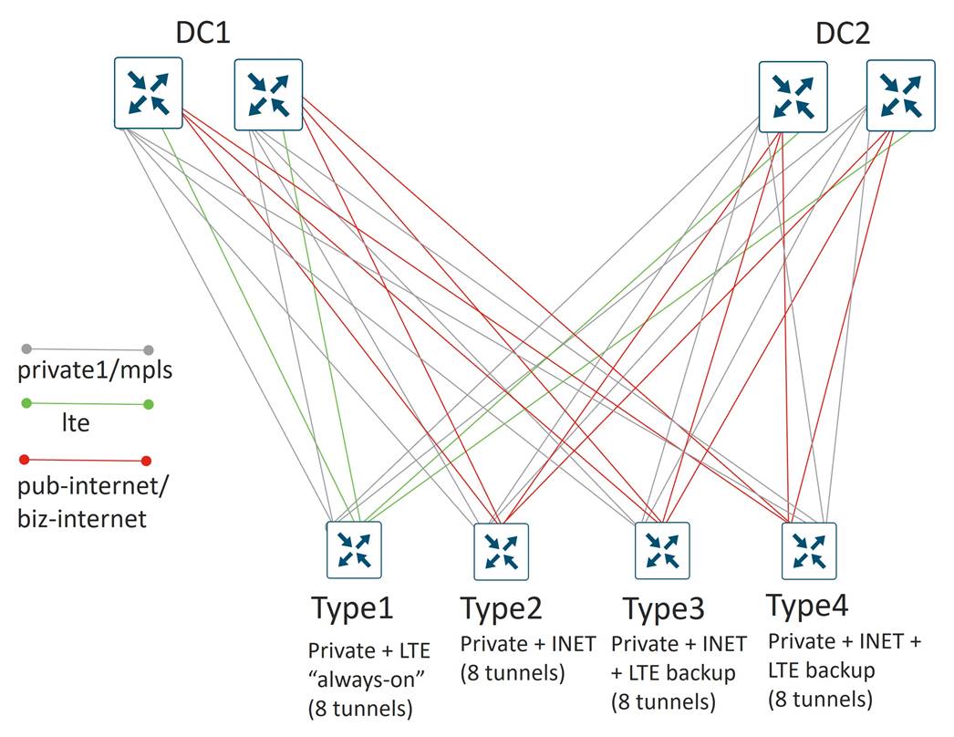
This reduces the number of tunnels down to 4 tunnels per WAN transport on the branch routers (1 tunnel to each hub WAN Edge router in each DC). For type 1 and 2 branches with 2 transports, each then only needs to support 8 tunnels total. On types 3 and 4 branches, the LTE configured as a backup does not activate until the other 2 TLOCs at the site lose their BFD sessions, so these branches only need to support 8 tunnels at one time as well.
Each hub router terminates a tunnel over each transport from each branch. Since there are 2 active transports from each branch, each hub router needs to terminate 2 * 500 spokes, or 1000 tunnels, which is well within the limits of any recommended Cisco Catalyst SD-WAN hub router platform.
WAN Edge Platform Selection
Several factors must be considered, and several questions should be asked when choosing the appropriate WAN Edge platform for a site. Some of these questions include:
● Is a hardware-based or software WAN Edge router on a virtualization platform desired?
● Are redundant WAN Edge routers or components (power supplies, fans) necessary to meet availability targets?
● How many IPsec tunnels will be terminated?
● How much IPsec throughput is required? Throughput performance on branch platforms will vary based on application packet sizes and whether features such as QoS, NAT, Network Based Application Recognition (NBAR), Flexible NetFlow, zone-based firewall, IPS/IDS, and AMP are enabled.
● How many ports are needed to connect to the WAN providers and what are the interface types required?
● Will the router need LAN switch network interface modules to connect users or devices directly, or will LAN functions be handed by an external, standalone switch?
● Is PoE or PoE+ support required for endpoints connecting to LAN switch network modules?
● Will the WAN Edge need to provide advanced branch features such as voice or on-prem security or need to support host compute modules for local virtual machines?
● Are service containers needed for uses cases such as SD-WAN embedded security appliances or ThousandEyes monitoring?
American GasCo used the Cisco Enterprise router selector tool to narrow their choices for SD-WAN platforms by providing information about their deployment collected during the network audit. This helped develop a short list of SD-WAN platforms that could be reviewed with their partner and Cisco account team with the following considerations:
● American GasCo decided to limit the Phase1 use cases to basic SD-WAN site-to-site connectivity, with no immediate plans for Direct Internet Access, SASE integration, or multi-cloud optimizations. Platform selection would consider these features as potential use cases for future phases.
● Branch sites would be deployed with a single WAN Edge router. Dual routers were deemed unnecessary for phase1 based on the reliability history of the ISR routers in the DMVPN deployment.
● WAN Edge routers for site types 2-4 were ordered with at least 8GB of memory to support advanced security features should they be required in future phases.
● WAN Edge routers with integrated Gigabit Ethernet LAN switch network interface modules (NIM) were ordered so that external, standalone ethernet switches could be removed.
● Existing ISR 4451-X routers that were recently purchased for the type 4 sites as DMVPN routers would be re-used and migrated to SD-WAN Edge routers.
● Cellular 4G/LTE modules are required for site types requiring LTE as an always-on or backup transport.
● There were no requirements for compute blades such as UCS-E modules.
● No integrated Wi-Fi modules were required since external APs will provide this function.
● There were no immediate plans for cellular/5G since most locations were in areas with no coverage.
● No T1 or SONET interfaces were required.
The following table details the American GasCo WAN Edge platform selections:
Table 10. American GasCo WAN Edge Platform Selections
| American GasCo Site Type |
Site Type Specs |
WAN Edge Router |
Memory |
WAN ports |
Cellular Ports |
Switch ports |
| Type 1 |
Up to 50 Mbps 1 GE + Cellular WAN 4 Switchports No advanced security required |
C1111-4PLTEEA Fixed Enterprise branch router, 1RU with PoE power modules
|
4G |
1 x GE |
Integrated |
4 |
| Type 2 |
Up to 150 Mbps 2 x GE WAN 8 Switchports Advanced security features possible in future phase |
C1111X-8P Fixed Enterprise branch router, 1RU with PoE power modules
|
8G |
2 x 1GE |
N/A |
8 |
| Type 3 |
Up to 300 Mbps 2 x GE + Cellular WAN 8 Switchports Advanced security features possible in future phase |
C1111X-8PLTEEA Fixed Enterprise branch router, 1RU with PoE power modules
|
8G |
2 x 1 GE |
Integrated |
8 |
| Type 4 |
Up to 500 Mbps 2 x GE + Cellular WAN 16 Switchports Advanced security features possible in future phase |
Existing ISR4451-X routers at type 4 sites to be converted to SD-WAN Modular, Enterprise branch, 2RU, 3 NIM slots, 2 SM slots with PoE power modules
|
8-32G |
4 x 1 GE onboard Additional 6 with service module SM-X-6X1G |
NIM-LTEA-EA |
16 SM-X-16G4M2X |
| Data center |
Up to 2x10G (1x10G per head-end router) 3 x GE N/A switchports |
C8500-12X Fixed high-performance routing, 1RU |
16G/32G/64G |
12x 1/10 GE ports |
N/A |
N/A |
The following is the High-Level Design (HLD) topology diagram:
In the low-level design (LLD) developed by American GasCo, design details were explored and documented in different areas, including:
● Control component deployment: covers details on the cloud-hosted deployment, how control components reachability is achieved from the private transports, factors that go into the number of control components and virtual machine (VM) sizing, how control components can access the data center network management servers, and what control components certificates are chosen
● Branch design: covers various design aspects of the branches, mainly the detailed site profiles with the platform and connectivity standards
● Data center design: covers various design aspects of the data center, including the transport and service-side design of the WAN Edge routers and a portion of the IP unicast routing design
● SD-WAN underlay design: covers the underlay routing and other underlay design considerations
● Firewall considerations: covers NAT design considerations for the network as well as firewall port considerations for successful SD-WAN device communication
● SD-WAN overlay design: covers various aspects of the overlay design, including site-ID design, control policy, cellular tunnel optimizations, VPN segmentation details, IP unicast routing, IP multicast routing, Quality of Service (QoS), and Application-Aware Routing (AAR)
Deployment Model
American GasCo opted for a Cisco cloud-hosted control component deployment in AWS. In this type of deployment, Cisco CloudOps is responsible for the initial overlay provisioning and ongoing monitoring and troubleshooting of the control components VM infrastructure. Cisco CloudOps also provides backups (snapshots) for the SD-WAN Manager configuration and statistics database and performs restoration in cases where disaster recovery is needed. American GasCo operators are provided network access into their AWS VPC and granted administrator rights to the SD-WAN Manager in order to provision and monitor their site WAN Edge devices.
The customer is responsible for managing their SD-WAN network overlay. The customer is also responsible for upgrading software and for opening TAC cases to arrange and authorize service windows when receiving certain notifications from CloudOps. The customer may also need to open TAC cases when notified about potential issues that need further investigation. This notification is done through email. Every cloud-hosted overlay has a single customer contract email address registered as the owner to receive alert notifications. This can be changed by opening a TAC case or through the Self-Service Portal at https://ssp.sdwan.cisco.com. Since one email address is supported, it is recommended that a group mailing list email address is used. For further information on the Cisco CloudOps service, along with a matrix of Cisco and Customer responsibilities, refer to the Cisco Catalyst SD-WAN CloudOps end-user guide.
Control Components Redundancy/High Availability
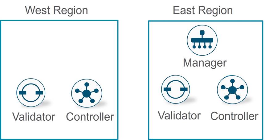
The control components infrastructure consists of multiple SD-WAN Validators, multiple SD-WAN Controllers, and a single node SD-WAN Manager or SD-WAN Manager cluster comprised of multiple SD-WAN Manager nodes. CloudOps distributes the SD-WAN Controllers and Validators in multiple cloud regions, so if one region becomes unreachable, the second cloud region can support the WAN Edge routers in the network. A SD-WAN Manager node or cluster is deployed in a single region, and CloudOps takes care of the disaster recovery in a second region should the primary SD-WAN Manager node or cluster fail.
Control Connections
In the Cisco Catalyst SD-WAN network, all SD-WAN devices need to authenticate and form control connections to the various control components (starting with the SD-WAN Validator) before being able to join the SD-WAN overlay. The number of control connections to a particular control component influences that control component’s ability to scale. One also needs to understand how control connections form so that the network design can accommodate these connections through the routing and firewall configurations.
WAN Edge Control Connections
For WAN Edge routers, the following control connections are formed:
● Temporary DTLS connection between each WAN Edge and one SD-WAN Validator – one connection on each transport. A SD-WAN Validator to connect to is chosen by the WAN Edge router from a list of IP addresses that is returned from the DNS server during SD-WAN Validator hostname resolution. Once the proper number of control connections have been made to the SD-WAN Manager and Controller, the SD-WAN Validator connections are torn down. This is different when the SD-WAN Controller and Manager control components make connections to the SD-WAN Validators, as their connections are persistent.
● Permanent DTLS or TLS (configurable) connection between each WAN Edge and one SD-WAN Manager instance – only one connection over one transport is chosen.
● Permanent DTLS or TLS (configurable) connections between each WAN Edge and two SD-WAN Controllers by default – connections to each over each transport.
Control Component Reachability from Private Transports
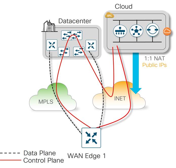
With control components being hosted in a public cloud, they are directly reachable by WAN Edge router Internet TLOCs. Since the private TLOCs cannot directly reach Internet-hosted control components, a strategy must be developed for how to handle these control connections.
American GasCo chose to use their data center Internet breakout for private transport reachability to the control components. This allowed control connections to be formed over the private TLOCs so each WAN Edge router has a redundant path to the control components in case of TLOC failures.
Control Components and Virtual Machine (VM) Sizing
In the cloud hosted deployment model, Cisco Cloud Operations is responsible for instantiating the control component virtual machines in the cloud service provider. In order to size the VMs resources (vCPU, memory, storage) accurately for the anticipated scale. Cloud Ops worked with American GasCo to obtain specific information about the end state design. This included the following information:
● Total of 500 branch sites, each with a single WAN Edge (spoke) router
● Two data centers, each with dual WAN Edge (hub) routers
● Four WAN transport colors at the data center and an average of 2 active transport colors at each remote site at a time
● Strict hub-and-spoke topology with dual hub routers in each data center.
● Application visibility enabled using Cisco Catalyst SD-WAN Application Intelligence Engine (SAIE), which sends flow statistics and application identifying information to the SD-WAN Manager for monitoring
| Tech Tip |
| One important data point that must be considered when sizing SD-WAN Manager resources is the volume of statistics expected to be received, processed, and stored by the SD-WAN Manager from the WAN Edge routers. This includes the statistics associated with up/down events on the site WAN Edge routers and the statistics associated with flow and application reporting for each site. While daily up/down events are relatively few in most deployments, flow and application statistics are continuously collected and exported to the SD-WAN Manager during regular intervals. This accounts for most of the traffic received by the SD-WAN Manager. |
Cisco Catalyst SD-WAN Application Intelligence Engine (SAIE)
Cisco Catalyst SD-WAN Application Intelligence Engine (SAIE) is the architecture for application classification. It can determine the contents of the packet for application visibility and can record the information for statistics collection. When application visibility is enabled through localized policy, flow records are enabled on the router and NBAR2 is used as the application classification engine on the WAN Edge router. Traffic flow statistics and its classification information are sent to the SD-WAN Manager, then collected and processed, where it can be displayed on the SD-WAN Manager GUI.
WAN Edge routers store statistics or aggregated statistics (starting in 20.6/17.6 code) and the SD-WAN Manager pulls this data from each WAN Edge router at pre-defined intervals and is processed/analyzed and stored on the SD-WAN Manager. Note that these statistics not only include SAIE statistics data but also other statistics, such as interface stats, QoS, App-route stats, firewall stats, etc. SAIE statistics typically make up a larger proportion of the statistics data.
A number of factors can increase the number of statistics being generated and processed by the SD-WAN Manager:
● Short-lived flows increase the SAIE statistics volume
● Running application visibility at the DC and remote sites in a hub-and-spoke topology doubles the amount of SAIE traffic sent to the SD-WAN Manager
● Modifying App-route timers to be more aggressive generates more App-route statistics
● Unstable links can increase the number of statistics being generated to the SD-WAN Manager
American GasCo ran an SD-WAN pilot deployment at 5 different remote sites running real traffic/applications and only enabled application visibility at the remote sites and not the DC sites. One reason for doing this is that the DC sites are dual-router sites and for application visibility to work with most applications, traffic symmetry would have to be assured. Also, with less statistics to deal with, the SD-WAN Manager requires less virtual machine resources.
After running the pilot for a week, American GasCo polled their SD-WAN Manager to estimate the volume of statistics being received from the five pilot sites. Using an API call (http://<SD-WAN Manager IP>/dataservice/management/elasticsearch/index/size/estimate), it was found that the 5 sites were generating a cumulative amount of 450MB of statistics per day. Taking this as a baseline, it was approximated that the SD-WAN Manager could expect to receive up to 45GB per day once the 500 sites were migrated to SD-WAN and exporting statistics.
Control Component Number Calculations
For number of control components and virtual machine sizing information, refer to the Cisco Catalyst SD-WAN Control Components Compatibility Matrix and Recommended Computing Resources. From this page, there is a link to the Cisco Catalyst SD-WAN Control Components Release 20.6.x (Cisco Hosted Cloud Deployment) which gives release-specific information. How many of each control component is needed depends on the number of WAN Edge devices in the network and the number of Cisco Catalyst SD-WAN Application Intelligence Engine (SAIE) statistics being generated. Based on the documentation, for 500 devices generating 45G of SAIE traffic per day, the following control component numbers are deployed:
Table 11. American GasCo Control Component Calculations
| Number |
|
| SD-WAN Manager |
One Node (Large Instance) |
| SD-WAN Validator |
2 |
| SD-WAN Controller |
2 |
CloudOps determines the instance type, vCPUs, memory, and storage for each control component as they can be subject to change.
Control Component Access to DC NMS Servers
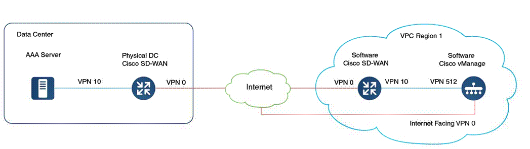
American GasCo security policy requires authentication to a TACACS/AAA server in the data center for users accessing the SD-WAN control components via HTTPS or SSH. The control components also need to send logging and SNMP trap information to NMS servers in the data center, which presents a challenge for cloud-hosted control component deployments on regional VPCs having no routed path to the customer internal network. To accommodate this requirement, it is necessary to connect the control component VPCs to the SD-WAN overlay so that they can join the fabric just like any other remote site.
The process to add the regional VPCs to a customer overlay is described in the Cisco SDWAN CloudOps Provisioning guide. It is important to do this step upfront since it affects the way the IP addressing is allocated on the control components. A summary of the steps is described below.
● Request CloudOps to instantiate a new software WAN Edge in each regional VPC, with the service VPN interface connected to the management VLAN that connects to VPN 512 of each control component. Additional licenses may need to be purchased so that the new software WAN Edge routers can be added to the device list of the SD-WAN Manager.
● Request CloudOps re-allocate the VPN 512 addresses from a private IP subnet not in use on the customer network. One /24 private IP address block is needed for each region. By default, the cloud-hosted control components are deployed with 10.0.0.0/16 subnets which might conflict with an existing subnet in the customer’s network. These IP prefixes are used to create the control components, and the subnets are then configured to be available within the Cisco Catalyst SD-WAN fabric.
● Onboard the new software WAN Edge into the customer SD-WAN overlay as a remote spoke site in each region, provisioning IPsec tunnels to each of the DC hub routers. Verify connectivity to the AAA server (and any other customer NMS servers) from the VPN 512 interface of the control components.
The following diagram illustrates this concept:
Certificates
Control components require signed device certificates that are used to authenticate other control components, along with the WAN Edge devices in the overlay network. In addition, proper root certificate chains must also be installed in each SD-WAN device so authentication between the devices can succeed since root certificates are used to trust device certificates. Once authenticated, control connections can be secured between the devices. For new Cisco cloud-hosted deployments, the customer can choose a Cisco-signed certificate, or alternatively, an Enterprise CA certificate.
American GasCo chose to implement Cisco PKI due to its simplicity and the fact that it would not require operations folks to maintain and operate the certificate system. There was also no security policy in place at American GasCo that required the use of Enterprise CA certificates.
Detailed Site Profiles – Platform and Connectivity Standards
American GasCo developed a set of standard site profiles for each store site type, specifying the WAN Edge platforms, VPN segmentation, and the LAN and WAN interface connectivity. These standards were used as site connectivity plans and served as the blueprints for the SD-WAN Manager templates and policies that were created during the implementation phase of the project.
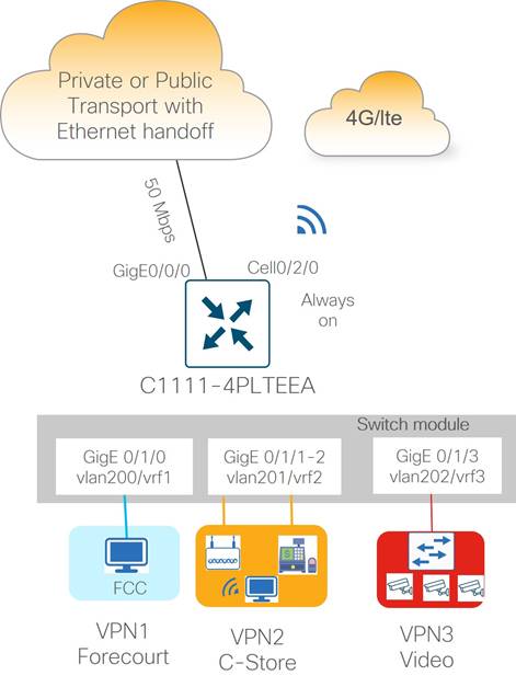
Type 1: Small Store (C1111-4PLTEEA)
Type 1 store site profiles support up to 50 Mbps of site throughput with N+1 transport redundancy using a combination of wired and wireless WAN connectivity. Wired ethernet connectivity to the transport carrier CPE device is provided by the routed Gigabit Ethernet interface that supports RJ45/copper and SFP/fiber cabling options. The integrated cellular module provides wireless connectivity to a 4G/LTE Internet service provider for the redundant WAN transport.
| ISR1100 routers with integrated LTE modules include a single cellular modem. The LTE modules support dual SIM cards for carrier redundancy but will only connect to a single LTE network at a time. At the time of this writing, only the industrial version of the ISR1100 (IR1101) supports dual LTE modems. Modular platforms that support pluggable LTE modules do not have this limitation. |
Ethernet LAN connectivity for up to 4 devices (computers, POS terminals, WLAN, Ethernet switch) is provided by the integrated 4-port Gigabit Ethernet LAN switch network interface module (NIM). The Ethernet switch ports are provisioned as access ports in VLANs 200, 201, or 202, with switched virtual interfaces (SVIs) mapped into VRFs 1, 2, or 3, respectively, for site segmentation.
| Tech Tip |
| PoE/PoE+ can be enabled on Gigabit Ethernet interfaces (4/8 PoE or 2/4 PoE+ ports on the 1100-8P and 2 PoE or 1 PoE+ ports on the 1100-4P), to provide power to external devices such as video endpoints and 802.11ac access points The C1111-8PWB and ISR-1100-POE4 are the Power over Ethernet (PoE) part numbers that must be ordered with the ISR1100 router if PoE or PoE+ is required to be enabled on the Gigabit Ethernet interfaces of the switch module. Together they provide 10/100/1000 Gigabit Ethernet connectivity with LAN services, 802.11b/ac WiFi, and 802.3at PoE/PoE+ support. |
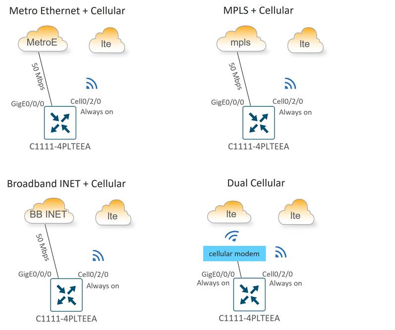
Small store subtypes were designed with different combinations of WAN transport connectivity to provide maximum flexibility to use whatever transport is available and most cost-effective at a particular location.
Type 1 WAN connectivity options include the following variants:
● Metro Ethernet + “Always-on” Cellular
● MPLS + “Always-on” Cellular
● Broadband Internet + “Always-on” Cellular
● Dual “Always-on” Cellular
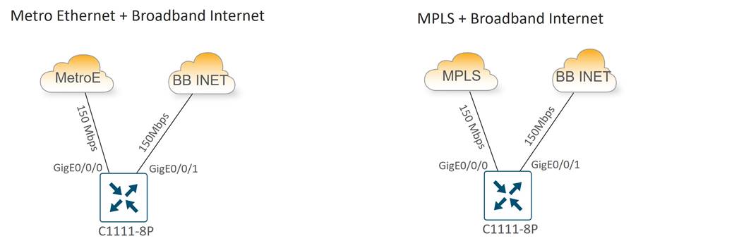
Type 2: Medium Store (C1111X-8P)
Type 2 store site profiles support up to 150 Mbps of site throughput with N+1 transport redundancy provided by private transport (MPLS or Metro Ethernet) and public Internet carrier circuits. Wired Ethernet connectivity to carrier CPEs is provided by the WAN Edge router integrated Gigabit Ethernet WAN modules, which supports RJ45/copper and SFP/fiber cabling.
Ethernet LAN connectivity for up to 8 devices (computers, POS terminals, WLAN AP, and video surveillance aggregation switch) is provided by the integrated 8-port Ethernet switch. The LAN switch Gigabit Ethernet ports are provisioned as access ports in VLANs 200, 201, or 202, with switched virtual interfaces (SVIs) mapped into VRFs 1, 2, or 3, respectively for site segmentation.
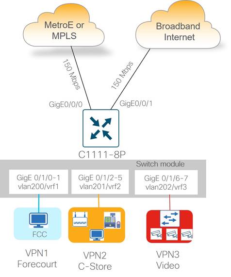
The two subtypes for the medium store include the following:
● Metro Ethernet + Broadband Internet
● MPLS + Broadband Internet
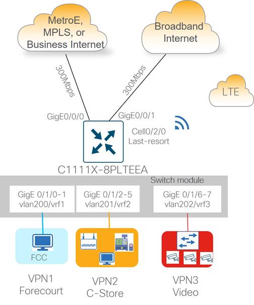
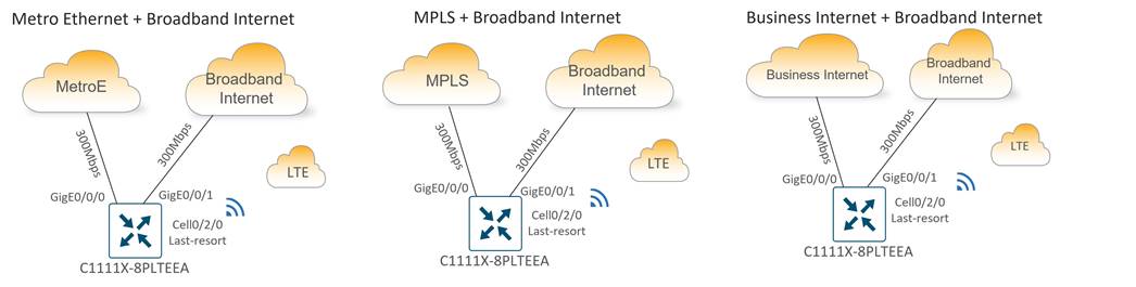
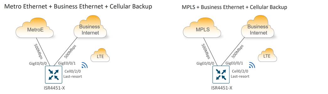
Type 3: Large Store (C1111X-8PLTEEA)
Type 3 store site profiles support up to 300 Mbps of site throughput with N+2 transport redundancy provided by private and public transport circuits with a cellular connection to LTE as a last resort circuit. Dedicated/Business Internet circuits can also be used in place of private circuits as an option. Ethernet connectivity to carrier CPEs is provided by the 2-port GE WAN module, which supports RJ45/copper and SFP/fiber cabling.
Ethernet LAN connectivity for up to 8 devices (computers, POS terminals, WLAN, and Ethernet switch) is provided by the integrated 8-port Ethernet switch. The Ethernet switch ports are provisioned as access ports in VLANs 200, 201, or 202, with switched virtual interfaces (SVIs) mapped into VRFs 1, 2, or 3, respectively for site segmentation.
There are three main subtypes for the large station:
● Metro Ethernet + Broadband Internet + Cellular Backup
● MPLS + Broadband Internet + Cellular Backup
● Business Internet + Broadband Internet + Cellular Backup
Type 4: Large Store/Regional Transport Gateway (ISR4451-X)
Type 4 sites support up to 500 Mbps of site throughput with N+2 transport redundancy provided by private and public transport circuits with a cellular connection to LTE as a last resort circuit. Dedicated Internet is preferred for type 4 site types over broadband Internet at the store location. Ethernet connectivity to carrier CPEs is provided by the 2-port GE WAN module, which supports RJ45/copper and SFP/fiber cabling.
The large store type 4 site types are unique because they can accommodate type 1 stores at remote locations without affordable access to American GasCo Metro Ethernet or MPLS transport carriers. These type 4 stores can act as a transport gateway, in addition to servicing their own site traffic. Type 1 stores can use short-haul private ethernet circuits and connect to a type 4 site that can be switched onto the private circuit with a TLOC extension configuration.
| Tech Tip |
| Type 1 stores connect their WAN interface/layer 3 ports to a layer 3 interface port of a type 4 store in the VPN 0 transport. This type 4 store interface is configured as a TLOC extension interface to connect the type 1 station to the private1 or mpls transport. Note that layer 2/SVI interfaces are not supported as TLOC extension interfaces. |
Site LAN connectivity for up to 16 Ethernet devices (computers, wireless APs, and POS terminals) is provided through a 16-port Ethernet switch NIM. Devices are partitioned across three VPNs for security and granular control.
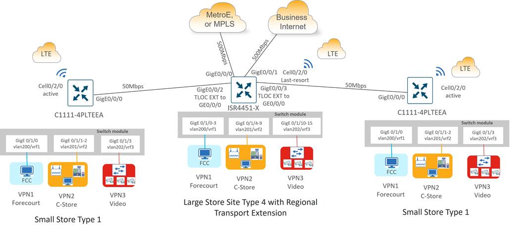
There are two main subtypes for the type 4 large store with regional transport extension
● Metro Ethernet + Business Internet + Cellular Backup
● MPLS + Business Internet + Cellular Backup
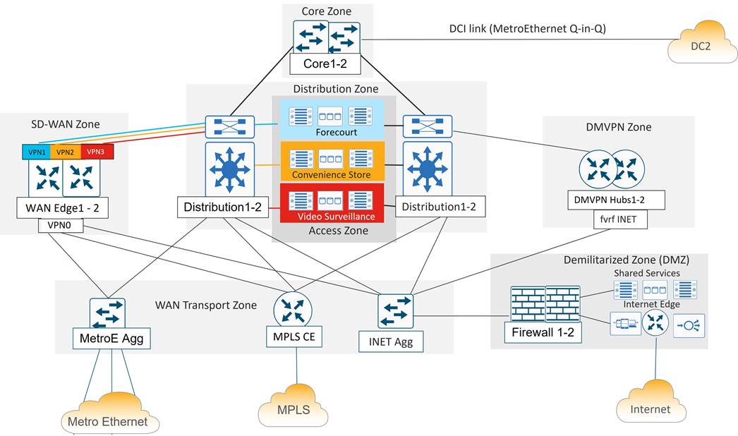
The Data Center devices are grouped into functional zones as shown in the following diagram. Each device in a zone connects to separate power supplies and is cabled to redundant devices in adjacent zones where applicable.
Overview
A brief description of each functional DC zone is as follows:
● Core zone: The core zone connects DC1 to DC2 over a private data center interconnect (DCI) circuit. Each DC has a pair of core routers that interconnect over different VLANs of a Metro Ethernet service providing Q-in-Q trunking.
● Distribution zone: The distribution zone connects to all zones in the data center. Includes a pair of layer 3 switches that controls the boundary between the WAN, access, and core layers. Distribution routers connect to each zone with redundant 10 Gigabit Ethernet connections and run multiple routing protocols.
● Access zone: The access zone contains layer 2 switches for the server and storage devices hosting the forecourt, convenience store and IP video surveillance applications.
● SD-WAN zone: The SD-WAN zone contains the Catalyst 8500 WAN Edge routers that function as the SD-WAN tunnel and routing “hubs” for the remote “spoke” WAN Edge routers.
● WAN transport zone: The WAN transport contains the aggregation devices that allow shared access to the WAN transports circuits. It includes the MPLS CE router, a layer 3 switch connecting to the Internet DMZ firewall pair, and a layer 3 switch that aggregates point-to-point and Metro Ethernet circuits connecting to remote sites. The WAN transport connectivity provided several benefits to American GasCo during the SD-WAN project rollout, which included:
◦ Allowed the SD-WAN Edge routers in the DC to share the MPLS and Internet bandwidth with the legacy WAN devices during the migration to SD-WAN
◦ Provided the remote SD-WAN Edge routers with MPLS and private circuits and underlay path to the shared network services, such as DNS, NTP, syslog, and SNMP
◦ Provided the remote SD-WAN Edge routers with MPLS and private circuits an underlay path to the Internet for access to the SD-WAN cloud-hosted control components
◦ Avoided the complexity associated with enabling an underlay routing path through the DC WAN Edge routers
● Demilitarized zone (DMZ): The DMZ provides secure access to shared network services and Internet for users and devices on all VPNs. In the segmented DC design, the DMZ firewall is the only point where traffic from different VPNs is allowed to converge, which is necessary to avoid duplicating shared services and Internet access for each VPN.
● DMVPN zone: The DMVPN zone contains the DMVPN hub routers that aggregate tunnels and routes from the legacy remote sites, utilizing the Internet as an underlay transport. The DMVPN zone was decommissioned after all remote sites were migrated to SD-WAN.
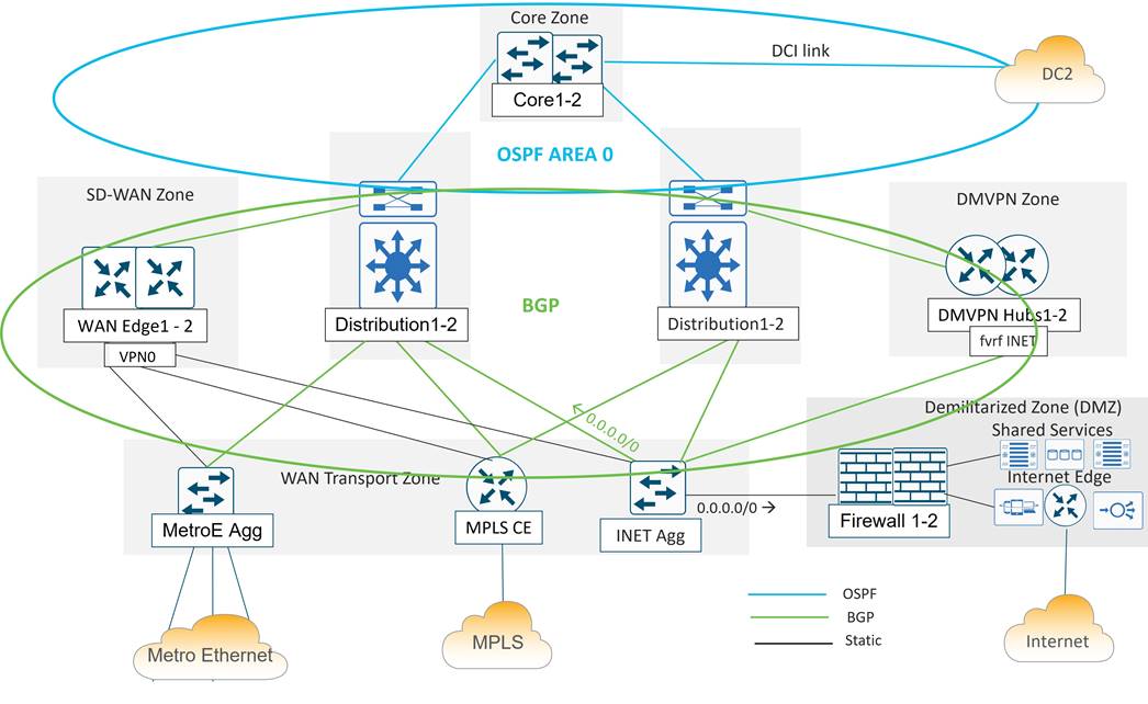
Data Center Routing Overview
In the data center, both BGP and OSPF is implemented. BGP is implemented throughout the distribution layer, the DMVPN zone, the LAN/service-side of the SD-WAN Zone, and throughout the WAN Transport Zone. OSPF is implemented from the distribution to the core routers and across the DCI link.
In the diagram below, the Metro Ethernet aggregation switch, the MPLS CE, the Internet aggregation switch, and the WAN Edge routers on the service-side interfaces use the BGP routing protocol to exchange routes with the distribution layer 3 switches. A static default route is distributed from the Internet aggregation switch into the BGP routing protocol for the purposes of outbound Internet routing.
The WAN Edge transport-side interfaces do not participate in BGP but instead use a static default route for underlay routing to establish control plane and data plane tunnels.
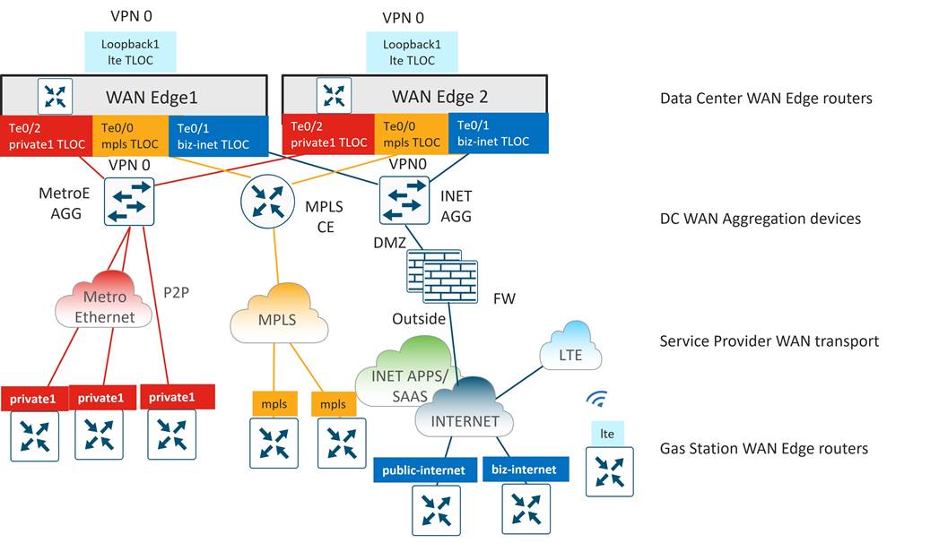
SD-WAN Edge Router Deployment and Related Details
A pair of Catalyst 8500 SD-WAN Edge routers were installed and connected to the distribution and transport zone devices with 10 Gigabit Ethernet interfaces. The following sections describe the details of the connectivity, SD-WAN TLOC colors, and service VPN segmentation.
Transport Side connections and TLOC colors
Each WAN Edge router is given 10 GE port connectivity to the MPLS CE, Internet, and Metro Ethernet aggregation devices in the transport zone as shown in the diagram below. The IP addresses on the Catalyst 8500 ports map into VPN 0 and represent the tunnel sources for TLOC colors mpls, biz-internet, and private1 for each WAN Edge router. A loopback interface was additionally configured as a tunnel interface on each WAN Edge router and mapped as TLOC color lte. This tunnel was bound to the Te0/1 interface using the bind command so that it shared the same underlay transport path as the biz-internet tunnel.
It would have been possible to avoid creating a separate tunnel color lte on the WAN Edge routers by allowing (or not using the restrict option on) the lte to biz-internet tunnels, but this was done so that protocol timers could be tuned specifically on the lte tunnels to minimize SD-WAN control and forwarding plane overhead. Details of these optimizations can be found in the overlay design section.
Service Side Connections and VPNs
The data center WAN Edge routers connect to each distribution router with back-to-back 10 GE interfaces configured as 802.1Q subinterfaces which serve as the ‘service VPN’ interfaces. These subinterfaces are mapped to VPNs 1-3 on each WAN Edge and distribution router so that end-to-end segmentation from branch to data center resource is preserved. Per-VPN BGP sessions were configured across these links to exchange the remote site and DC prefixes for each VPN.
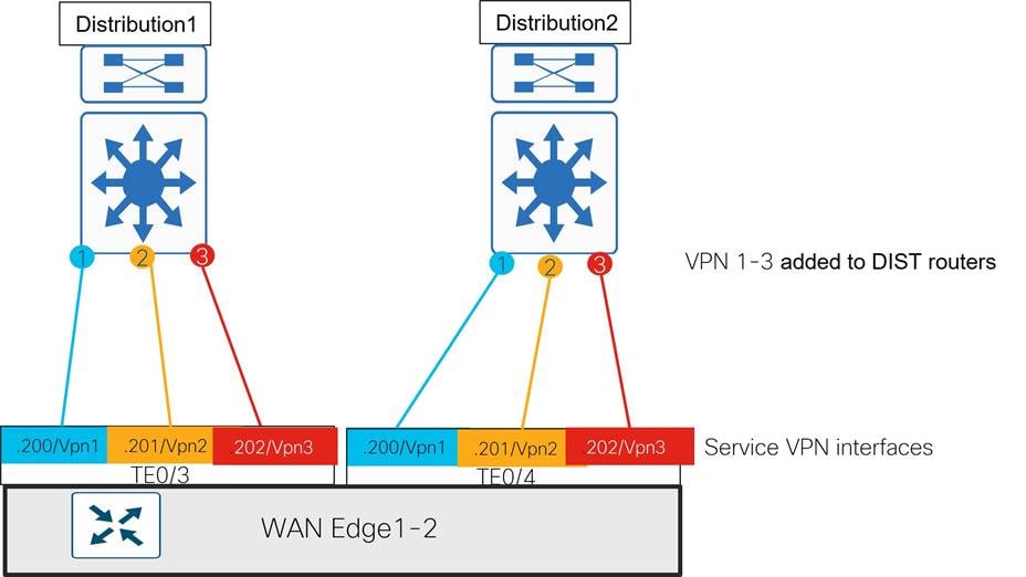
Changes to other Data Center Devices for End-To-End VPN Segmentation
Other changes were made to existing data center devices to support the end-to-end segmentation goal of American GasCo:
● Additional VPNs 1-3 were added to the core routers with per-VPN instances of OSPF routing to support end-to-end segmentation across the DCI circuit.
● Additional VPNs 1-3 were added to the Internet aggregation switch with per-VPN instances of BGP routing to the distribution routers to provide segregated Internet access for each VPN.
● Additional VLANs were added between the Internet aggregation switch and DC firewall interfaces to support segmentation of traffic destined to shared services or the Internet. Each firewall was configured with three unique inside interfaces to support this connectivity, but not partitioned into VPNs.
The VPN segmentation on each device is shown in the overall diagram below.
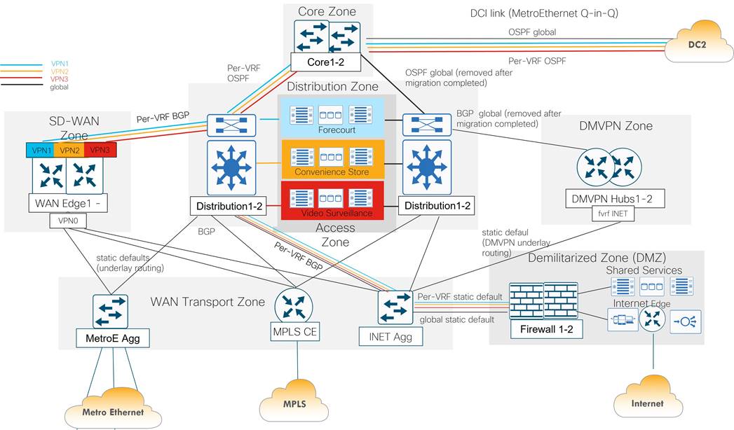
VPN segmentation of the core, distribution, SD-WAN Edges, and firewall are shown in the below detailed diagram. How the default route is distributed through the data center and VPN segments is also shown.
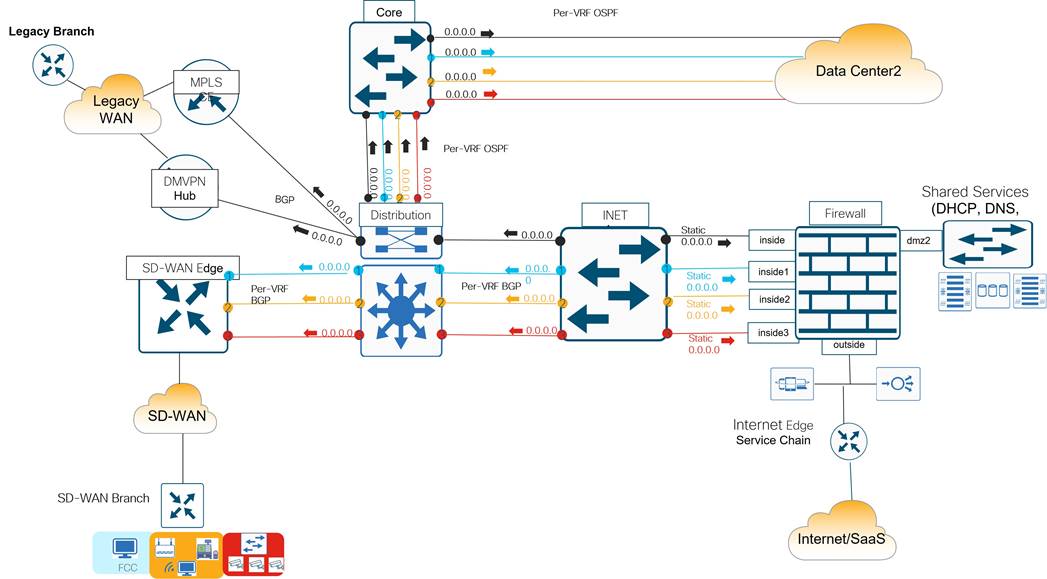
WAN Edge/Distribution Routing
The following describes more details on the data center routing, specifically from the WAN Edge routers to the distribution layer. The WAN Edge routers peer using the BGP routing protocol in each VRF to the distribution routers.
● WAN Edge routers: The WAN Edge routers redistribute all remote site routes learned from OMP into BGP towards the distribution routers.
● Distribution routers: The distribution routers originate summary routes into BGP to advertise the following prefixes to the DC WAN Edge routers:
◦ 10.100.0.0/16 (DC1 prefix block)
◦ 10.110.0.0/16 (DC2 prefix block)
◦ 10.0.0.0/8 (RFC 1918 summary to cover any future branch-to-branch routing requirements)
◦ 0.0.0.0/0 (default route for branch for Internet path sourced from the DC)
Each data center advertises its own summary route in addition to its partner data center’s summary route for redundancy. This allows remote sites to utilize the DCI link as an alternate/backdoor path in the event of a complete WAN transport failure at either data center.
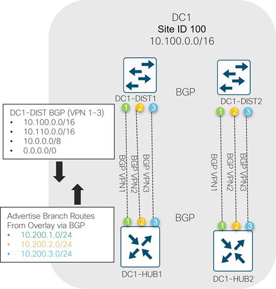
Distribution/Core Routing
The following describes more details on the data center routing, specifically from the distribution to the core layer. The distribution routers peer using the OSPF routing protocol in each VRF to the core routers.
● Distribution routers: The distribution routers redistribute BGP into OSPF, which includes branch overlay routes from the WAN Edge routers, local DC routes, and the default route.
● Core routers: The core routers advertise core routes and opposite data center routes from the DCI link to the distribution routers via OSPF.
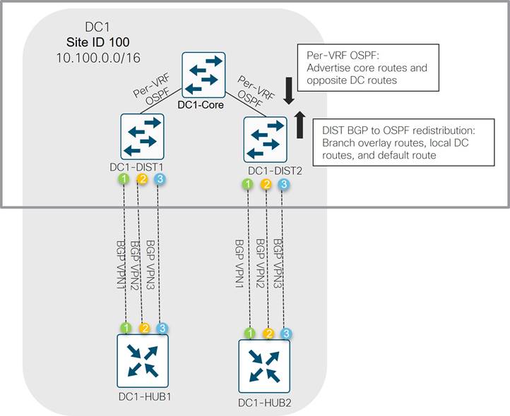
DC-to-DC Routing
Since the DCI circuit is also the intended to be used as an alternative backdoor path for store traffic in the event of a complete failure of WAN Edge routers in either DC, it is necessary for each WAN Edge router in both data centers to announce the prefixes associated with the other DC in addition to their own and the default route. The following describes more details on the DC1 to DC2 routing across the DCI link, which runs OSPF.
● DC1: The core routers in DC1 advertise the overlay routes, local DC1 routes, DC1 route summary (10.100.0.0/16), overlay route summary (10.0.0.0/8) and the default route (0.0.0.0/0) to the Internet per VPN to DC2
● DC2: The core routers in DC2 advertise the overlay routes, local DC2 routes, DC2 route summary (10.110.0.0/16), overlay route summary (10.0.0.0/8) and the default route (0.0.0.0/0) to the Internet per VPN to DC1
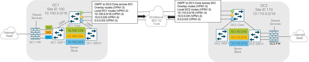
Internet Routing
Firewall
The firewall in the data center allows the inside network to access the Internet and shared services block. It has multiple interfaces, including several inside and dmz interfaces and an outside interface.
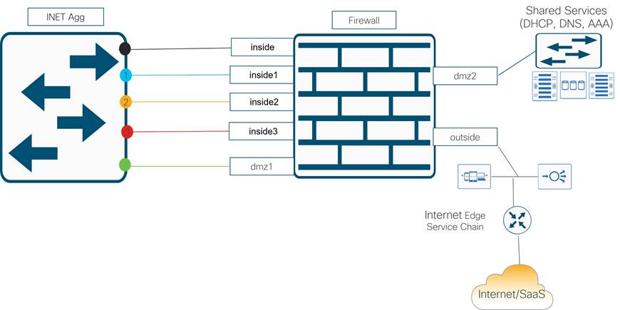
● inside: The interface that attaches directly to the Internet aggregation switch which attaches directly to the distribution switches and resides in the global routing table. It transports any traffic in the data center that is part of global table from the inside of the network to shared services or to applications residing on the Internet. It is also responsible for transporting private1 and mpls underlay control connection traffic to the cloud-based control components on the Internet.
Because of end-to-end segmentation, there are separate inside interfaces for each service VPN. Any user traffic in the SD-WAN overlay that needs to access shared services or the Internet comes through these interfaces.
◦ inside1: The inside interface for VPN 1, or the forecourt VPN
◦ inside2: The inside interface for VPN 2, or the convenience store VPN
◦ inside3: The inside interface for VPN 3, or the video services VPN
● dmz1: The interface that attaches to the Internet aggregation switch which attaches directly to the VPN 0 Internet interface of the WAN Edge router, as well as the transport interface of the DMVPN routers. This interface transports encrypted control plane traffic over the Internet to the cloud-based control components and encrypted tunnel traffic from the WAN Edge routers to other WAN Edge routers over the Internet transport. It also transports IKE tunnels and encrypted data traffic from the DMVPN routers to other branch devices still running DMVPN.
● dmz2: This interface attaches to the shared services switch so any device within the network can access.
● outside: The interface that attaches directly to the Internet Edge service chain which leads to the Internet transport.
Internet Routing Paths
The following are a description of the Internet routing paths through the data center.
Table 12. DC Internet Routing Paths
| # |
Source |
Description |
DC Path |
Destination |
| 1 |
SD-WAN Edge routers in DC (VPN 0) |
Encrypted control plane traffic |
WAN Edge > INET Agg > (dmz1) FW (outside) > Internet Edge > Internet |
SD-WAN cloud-based control components |
| 2 |
SD-WAN Edge routers in DC (VPN 0) |
Encrypted data plane traffic (biz-internet or lte color) |
WAN Edge > INET Agg > (dmz1) FW (outside) > Internet Edge > Internet |
Other SD-WAN branch routers (biz-internet, public-internet, or lte color) |
| 3 |
DMVPN routers in DC (transport interface) |
IKE and encrypted data plane traffic |
DMVPN router > INET Agg > (dmz1) FW (outside) > Internet Edge> Internet |
Other DMVPN branch routers |
| 4 |
SD-WAN branch user from VPN 2 |
Application traffic |
WAN Edge router > Distribution router > INET Agg > (inside2) FW (outside) > Internet Edge > Internet |
Internet server |
| 5 |
DMVPN branch user |
Application traffic |
DMVPN router > Distribution router > INET Agg > (inside) FW (outside) > Internet Edge > Internet |
Internet server |
| 6 |
MPLS or Metro Ethernet branch router |
Control plane underlay traffic |
MPLS CE or MetroE Agg > Distribution router > INET Agg > (inside) FW (outside) > Internet Edge > Internet |
SD-WAN cloud-based control components |
In the following diagram, the various Internet routing paths within the data center are illustrated. The numbers in the first column of the table correspond to the path source number in the diagram, and the logical paths are color-coded.
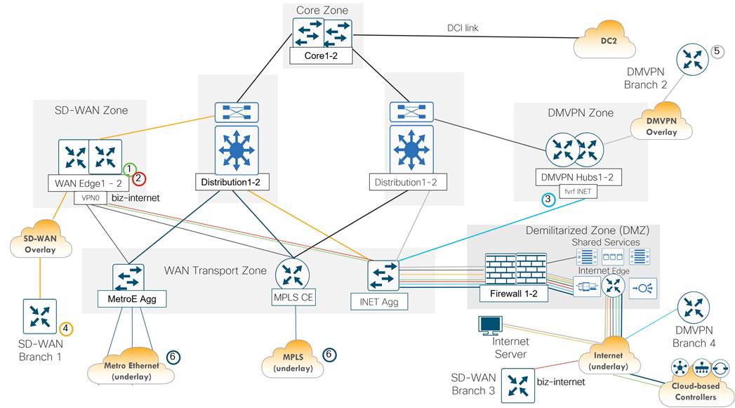
The underlay consists of the end-to-end IP routing path over which WAN Edge router SD-WAN tunnels are built. The underlay is the foundation of the SD-WAN network and must be stable, resilient, and scalable. The network design of the SD-WAN underlay is largely driven by the WAN transport provider capabilities, but other factors such as the extent of fabric mesh, presence of NAT, and co-existence with existing circuits and devices at hub locations must be considered.
MPLS Underlay Routing
The service provider is responsible for controlling most of the underlay infrastructure for overlay tunnels traversing MPLS apart from the MPLS CE router in the customer data center. The MPLS CE router functions as an aggregation device for the WAN Edge routers that share access to the circuit connecting to the MPLS PE router.
The control traffic on the branch WAN Edge routers reaches the cloud-based control components by following the default route over the MPLS transport to reach the Internet at the data center. The branch WAN Edge routers also form IPsec tunnels over the MPLS transport to each DC WAN Edge router. This is accomplished by the following underlay routing setup:
Branch
● The TLOC color mpls sourced on the branch WAN Edge uses the MPLS provider-assigned IP address on the Ethernet WAN interface.
● A static route is installed in the transport VPN of the branch WAN Edge router that points to the MPLS provider as the next-hop for MPLS tunnel traffic.
● The MPLS provider advertises the branch WAN Edge mpls TLOC subnet into the provider cloud/network.
Data Center
● The TLOC color mpls sourced on the DC WAN Edge uses the customer-assigned IP address on the Ethernet WAN interface.
● A static route is installed in the transport VPN of the DC WAN Edge router that points to the MPLS CE router as the next-hop for MPLS tunnel traffic.
● The MPLS CE router is configured to run BGP and the DC WAN Edge mpls TLOC must be advertised into the provider cloud from DC CE1 to PE1.
● The Internet aggregation switch uses BGP to advertise a default route to the Internet to the MPLS CE. The MPLS CE advertises this default into the MPLS provider cloud so control traffic on the branch WAN Edge routers can be routed to the cloud-based control components on the Internet through the DC.
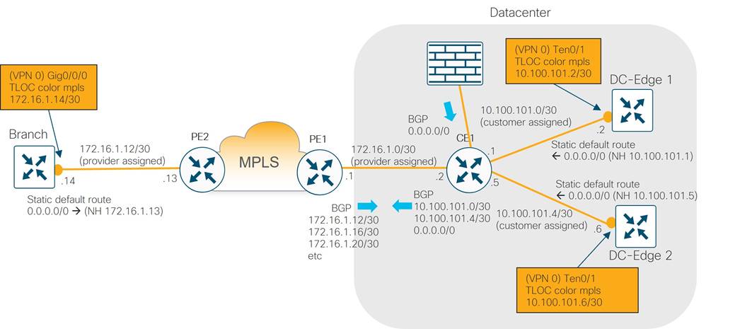
Private1 Underlay Routing
Private1 color is assigned to point-to-point and Metro Ethernet transports. An aggregation switch in the data center is used to terminate all circuits, and BGP is only needed in the underlay to advertise the DC private1 color from behind the aggregation switch and on any regional hub Edge routers which may be acting as a transport gateway for other branches.
The control traffic on the branch Edge routers follows the default route over the private1 transport to get to the Internet at the data center to reach the cloud-based control components. The branch WAN Edge routers also form tunnels over the private1 transport to each DC WAN Edge router. This is accomplished by the following underlay routing setup:
Branch/Regional Transport Gateway
● The TLOC color private1 sourced on the regional hub WAN Edge uses the customer-assigned IP address on the Ethernet WAN interface.
● A static route is installed in the transport VPN of the regional hub WAN Edge router that points to the DC Aggregation switch as the next-hop for private1 tunnel traffic.
● Only the WAN Edge acting as a regional transport gateway runs BGP and advertises any connected WAN Edge private1 TLOC subnets to the DC aggregation switch.
Data Center
● The TLOC color private1 sourced on the DC WAN Edge uses the customer-assigned IP address on the Ethernet WAN interface.
● A static route is installed in the transport VPN of the DC WAN Edge router that points to the DC aggregation switch as the next-hop for private1 tunnel traffic.
● The DC aggregation switch is configured to run BGP to receive any private1 TLOC subnets sitting behind regional WAN Edge hub routers. The DC aggregation switch has complete routing information for all the private1 TLOCs since all the private1 transports are aggregated there.
● The Internet aggregation switch uses BGP to advertise a default route to the Internet to the DC Aggregation Switch. The DC Aggregation Switch does not need to advertise this default to the WAN Edge routers connected via the private1 color because all default traffic is statically defined to go to the DC Aggregation Switch. Control traffic on the branch WAN Edge routers can be routed to the cloud-based control components on the Internet through the DC through the DC Aggregation Switch.
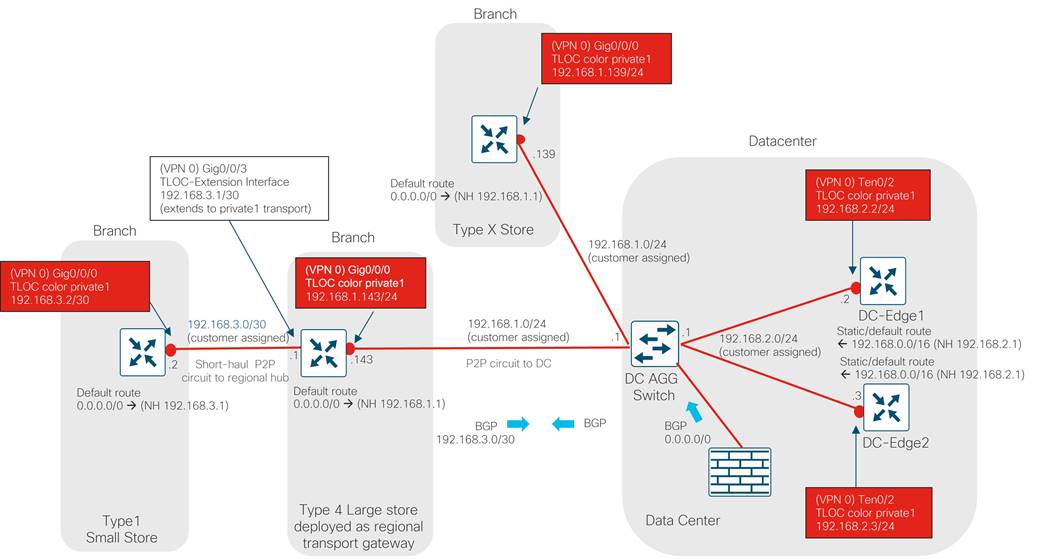
Internet/LTE Underlay Routing
The Internet underlay is used for three different colors:
● biz-internet (present at the data center and at some branches)
● public-internet (present at some branches)
● lte (present at branches as a separate transport and shares underlay with the biz-internet color at the data center)
The SD-WAN color biz-internet or public-internet is assigned to the Internet transports at the branches. The underlay path includes the ISPs and the data center components used for the biz-internet color underlay (ISP circuit, HA-pair of firewalls and Internet aggregation switch (not shown in the logical diagram) plus the Ethernet links that connect to the WAN Edge routers).
The SD-WAN color lte is assigned to Cellular 4G/LTE transports on the branches. The lte underlay path includes the cellular network, intermediate ISPs, and Data Center components used for biz-internet color underlay (ISP circuit, HA-pair of firewalls and Internet aggregation switch (not shown in the logical diagram) plus the Ethernet links that connect to WAN Edge routers, and finally, the loopback interfaces on the data center WAN Edge routers which serve as lte TLOC sources).
The LTE, biz-internet, or public-internet TLOC control connection traffic on the branch Edge routers goes directly through the LTE or Internet transport to the cloud-based control components and there is no need to route this traffic through the data center. The branch WAN Edge routers form data tunnels over the Internet transports to each DC WAN Edge router. The following data plane connections are formed:
● The color biz-internet on the branch router forms a data plane tunnel with the color biz-internet on each data center WAN Edge router.
● The color public-internet on the branch router forms a data plane tunnel with the color biz-internet on each data center WAN Edge router.
● The color lte on the branch router forms a data plane tunnel with the color lte on the loopback interfaces on each data center WAN Edge router.
The control and data plane connections are accomplished by the following underlay routing setup:
Branch
● The TLOC color biz-internet or pub-internet sourced on the branch WAN Edge uses the ISP provider-assigned IP address on the Ethernet WAN interface (either static or through DHCP). The TLOC color lte sourced on the branch WAN Edge uses the ISP provider-assigned IP address on the Ethernet WAN interface through DHCP.
● A route is installed in the transport VPN of the branch WAN Edge router (statically assigned or through DHCP) that points to the ISP provider as the next-hop for Internet or LTE tunnel traffic.
● The ISP provider advertises the branch WAN Edge Internet or LTE TLOC subnet into the provider cloud/network.
Data Center
● The TLOC color biz-internet sourced on the DC WAN Edge Ethernet interface and the TLOC color lte sourced on the DC WAN Edge loopback interface use customer-assigned IP (private RFC 1918) addresses.
● A static route is installed in the transport VPN of the DC WAN Edge router that points to the DC FW as the next-hop for Internet and LTE tunnel branch traffic.
● As the WAN Edge biz-internet or lte TLOCs pass through the firewall toward the ISP, the TLOC IP addresses are translated into publicly routable IP addresses so they can be routed through the Internet.
● For DC traffic flowing from ISP to the data center, the DC firewall has connected routes to the biz-internet TLOCs of the WAN Edge routers in the DC and static routes to the lte TLOCs (loopback interfaces) of the WAN Edge routers in the DC.
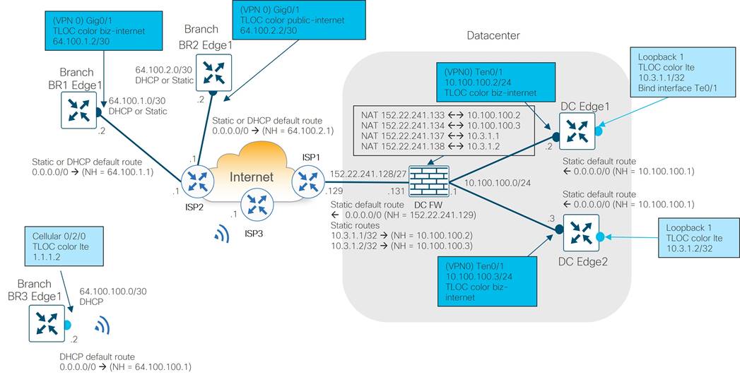
| Tech Tip |
| With dynamic IP addressing in Cellular 4G/LTE, the router installs the default route received from the provider with an administrative distance of 254. If there is a default route on a different, active transport with a lower admin distance, the router will not use the Cellular 4G/LTE transport until the primary transport is down. This prevents the Cellular 4G/LTE transport from being used in “always-on” mode. To remediate this, assign an admin distance of 254 to each static default route for the other active transports. |
NAT considerations
For traffic that needs to reach endpoints on the Internet but may be privately addressed inside the customer network, network address translation (NAT) is needed for those sources so they can be publicly routable. NAT types used at different sites need to be carefully considered in the SD-WAN design because it can affect whether sites can form connections and communicate directly with each other. In this design, the WAN Edge routers in the DC are addressed with private RFC 1918 addresses, so NAT is needed on the source IP addresses that are required to use the Internet transport. Traffic needing NAT includes:
● DC WAN Edge biz-internet and lte TLOC control connections to the cloud-based control components
● DC WAN Edge biz-internet and lte TLOC data plane connections/BFD sessions to other WAN Edge routers located at other sites.
The WAN Edge routers at the different branch sites are not sitting behind firewalls, but in the future, there may be new branch types which may have this requirement. It is important to ensure at least one side of the WAN tunnel can always initiate a connection inbound to a second WAN Edge even if there is a NAT firewall in the path.
It is recommended to configure full-cone, or one-to-one NAT at the data center or hub site so that, regardless of what NAT type is running at the branch (restricted-cone, port restricted cone, or symmetric NAT), the branch can initiate traffic to the hub site’s WAN Edge router TLOCs using IPsec at a minimum without issue. American GasCo configured one-to-one NAT in the Internet firewall for four of the TLOCs at the primary data center:
● biz-internet for DC WAN Edge 1
● lte loopback for DC WAN Edge 1
● biz-internet for DC WAN Edge 2
● lte loopback for DC WAN Edge 2
Dynamic NAT is used for everything else leaving the data center to access the Internet, which includes:
● User traffic from the data center or from the SD-WAN or DMVPN overlay originating from the branches accessing the Internet through the data center Internet exit
● Control connection traffic on the private1 or mpls underlay from the branches needing to reach the Internet through the data center to connect to the cloud-based control components
Firewall Port Considerations
American GasCo has strict incoming and outgoing firewall rules implemented at the data center Internet firewall, which allows only the needed IP addresses and port numbers, and blocks everything else. All traffic that is needing to traverse the Internet firewall in the data center was identified. Traffic includes:
● WAN Edge control connection (DTLS) traffic to the cloud-based control components
◦ From the DC WAN Edge routers to the Internet in the firewall DMZ network
◦ From the branch WAN Edge routers from Metro Ethernet and MPLS transports to the Internet in the firewall inside network
● WAN Edge data plane (IPsec) traffic to other branch WAN Edge data plane (IPsec) over color biz-internet through the firewall DMZ network
● Overlay user traffic from the branches and DC user traffic accessing the Internet through the data center
The following table shows the source and destination traffic that is permitted from an inside to outside interface, or from the DMZ to the outside interface through the firewall. Note that traffic is bidirectional, so the reverse traffic is allowed in the opposite/incoming direction. Note:
● Port hopping is disabled on the WAN Edge routers in the data center but kept enabled by default on the branch routers.
● No port offsets are configured and DTLS is the protocol used for control connections (which is the default).
● A WAN Edge may hash to any one of 8 SD-WAN Manager cores, so all 8 ports should be allowed. Each core corresponds to a separate port number.
● A WAN Edge may hash to any one core of a SD-WAN Controller and how many cores are available depends on how many vCPUs are allocated to the SD-WAN Controller (maximum of 8 cores). Each core corresponds to a separate port number.
Table 13. Firewall IP Addresses and Ports Allowed in Outgoing Direction
| Source device |
Source port |
Firewall Source Interface |
Destination device |
Destination port |
Firewall Destination Interface |
| DC WAN Edge 1-2 biz-internet and lte TLOC (DTLS control connections) |
UDP 12346 |
DMZ |
Cloud-hosted SD-WAN Manager public IP address |
UDP 12346, 12446, 12546, 12646, 12746, 12846, 12946, 13046 |
Outside |
| Cloud-hosted SD-WAN Controllers public IP addresses |
UDP 12346, 12446, 12546, 12646, 12746, 12846, 12946, 13046 |
Outside |
|||
| Cloud-hosted SD-WAN Validator public IP addresses |
UDP 12346 |
Outside |
|||
| All branch private1 TLOCs and mpls TLOCs (DTLS control connections) |
UDP 12346, 12446, 12546, 12646, 12746, 12846, 12948, 13046 |
Inside |
Cloud-hosted SD-WAN Manager public IP address |
UDP 12346, 12446, 12546, 12646, 12746, 12846, 12946, 13046 |
Outside |
| Cloud-hosted SD-WAN Controllers public IP addresses |
UDP 12346, 12446, 12546, 12646, 12746, 12846, 12946, 13046 |
Outside |
|||
| Cloud-hosted SD-WAN Validator public IP addresses |
UDP 12346 |
Outside |
|||
| DC WAN Edge 1-2 biz-internet TLOC (IPsec data plane) |
UDP 12346 |
DMZ |
All branch biz-internet and public-internet TLOCs |
UDP 12346, 12366, 12386, 12406, 12426 |
Outside |
| DC WAN Edge 1-2 lte TLOC (IPsec data plane) |
UDP 12346 |
DMZ |
All branch lte TLOCs |
UDP 12346, 12366, 12386, 12406, 12426 |
Outside |
| User traffic |
Any |
Inside |
Allowed application servers |
Allowed applications |
Outside |
The SD-WAN overlay design addresses components of the LLD that define the fabric structure and dictate how application traffic is handled and forwarded into and out of the fabric. This section discusses the major components of the overlay design:
● Site ID planning
● Hub-and-spoke tunnel topology
● Cellular tunnel optimizations
● VPN segmentation
● SD-WAN overlay routing across the transports
● IP unicast routing
● IP multicast routing
● Quality of Service (QoS)
● Application-Aware Routing (AAR)
Site ID Planning
It is important to plan out various aspects of your SD-WAN deployment carefully so it is easier for configuration, day-to-day operations, and maintenance. A site ID scheme is one of these important aspects to address.
A site ID scheme should be chosen carefully, as this makes it easier to apply centralized policy. When you apply policy, you apply policy to a list or range of site IDs (ex. 100, 200-299), and there is no wildcard support. Site ID schemes can be set up in different ways, where digits represent different countries, regions, site types, and store numbers. Different site types can be set up according to the types of policies that need to be applied so applying policy is easier. When a new site is created, just creating a site ID that falls into the matching range of a policy will automatically cause the policy to be applied to it.
American GasCo used the following Site ID scheme for their network. Their hub sites are in the range 100-199, where the primary DC is 100, and the secondary DC is 110.
American GasCo may expand outside the Southeast one day, so they decided to use the first digit in the site ID scheme to indicate region. The second digit represents site type, and the 3rd and 4th digits represent store subtype, and the 5th-7th digits represent the store number. Store numbers in the 500-999 range are reserved for stores that connect to large stores that act as regional transport gateways.
Table 14. American GasCo Site-ID Scheme
| Representation |
Examples |
|
| 1 |
Region |
0=Southeast, 1=Future use |
| 2 |
Site type |
0=Hub sites, 1=Type 1 sites, 2= Type 2 sites, 3= Type 3 sites, 4= Type 4 sites, 5= Future use |
| 3-4 |
Store subtype |
00=Hub sites, 01 =Subtype 1, 02 = Subtype 2, 03 = Subtype 3, etc. |
| 5-7 |
Store number |
001, 002, 003…100, 101, 102, etc. 500-999 = Sites behind a regional transport gateway branch WAN Edge router, where 500-525 is behind a regional branch at a certain location, 526-550 is behind a regional branch in another location, etc. |
Examples of the store subtype are shown in the following table:
Table 15. American GasCo Site-ID Scheme: Store Subtypes
| Store Subtype (Digit 3-4) |
Representation |
| 00 |
Hub Routers |
| 01 |
Direct Internet Access Site |
| 02 |
“Always-on” Cellular Site |
| 03 |
Cellular Backup Site |
| 04-xx |
Future Use |
Examples of Site IDs include:
● Site ID 100 (primary DC), Site ID 110 (Secondary DC)
● Site ID 0102100 (site type 1, subtype 2 (“always-on” cellular), store ID 100)
● Site ID 0201151 (site type 2, subtype 1 (Direct Internet Access), store ID 151)
Hub-and-Spoke Tunnel Topology
American GasCo deployed a dual hub-and-spoke tunnel topology with the store WAN Edge routers functioning as spokes and the data center WAN Edge routers in DC1 and DC2 as the hubs. The hub-and-spoke topology was implemented with SD-WAN Controller control policies that determined whether a TLOC or service VPN route learned from a particular WAN Edge router should be advertised or filtered to other WAN Edge routers. To block a tunnel from forming encrypted BFD and data plane sessions between two endpoints, the TLOC route should be filtered so the BFD sessions and secure data tunnels cannot be formed. Note that American GasCo also filtered the service-side routes from the other spokes as these routes become unreachable due to the TLOC (the next-hop) being filtered. One option is to modify the next-hop in the spoke routes to be the data center, but American GasCo instead filtered the more specific branch routes and sent route summaries and the default route to each spoke to draw traffic toward the data centers.
American GasCo uses a high-speed data center interconnect (DCI) link with no SD-WAN overlay configured on it between the data centers for redundancy and data backups, so the SD-WAN tunnels between the data centers over the Internet, MPLS, and Metro Ethernet links are filtered so traffic uses the DCI exclusively between the data centers. Note that the DC routes were filtered as well from the opposite data center so routes did not appear as invalid since their TLOCs were filtered (so IPsec tunnels could not be formed).
A description of the centralized policy with the SD-WAN Controller logic follows:
Table 16. Centralized Policy: Hub-and-Spoke Topology/DC Tunnel Filtering
| Description |
SD-WAN Controller Logic |
Policy Applied to Site Lists |
Direction Policy Applied on SD-WAN Controller |
|
| TO-SPOKES |
Create spoke role in Hub/Spoke Topology |
Allow TLOC routes and service VPN routes with site IDs identified as data centers and block all others |
All branches |
Outgoing |
| TO-HUBS |
Create hub role in Hub/Spoke Topology Prevent Inter-DC Tunnels |
Allow TLOC routes and service VPN routes originated from WAN Edge routers with site IDs identified as branches, block all others (including for DC1 to DC2 tunnel) |
All hubs |
Outgoing |
An example hub and spoke control policy is shown below:
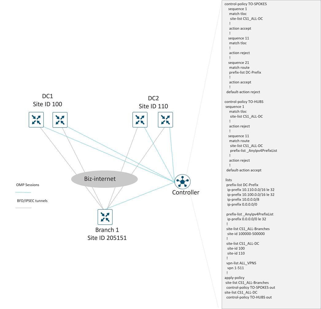
A guiding principle of Cisco Catalyst SD-WAN overlay design is to strive for a “transport-independent” design where tunnel characteristics are deployed consistently regardless of the type of underlay transport that are built upon. This abstracts the overlay design from particulars of the underlay transport carriers and simplifies the design. A pure transport-independent design would have identical tunnel characteristics with respect to encapsulation, MTU, QoS, and protocol-specific timer values. One exception to this principle are the SD-WAN tunnels built over low-bandwidth cellular 4G/LTE transports, where special modes of operation and tuning of the protocol timers are recommended to reduce costs and maximize throughput.
SD-WAN tunnels over cellular networks can be deployed in an ‘always-on’ mode just like any other transport, or as a ‘last-resort’ where they are brought up only when all other tunnels on a WAN Edge router are down.
● American GasCo deployed cellular transports as ‘always-on’ for their Type 1 sites to augment the bandwidth of Ethernet-connected transports and to reduce convergence time during transport failures.
● The American GasCo Type 3 and Type 4 sites with dual Ethernet transport circuits utilized cellular transports only as a last resort. In this mode, the cellular radios remain active and connected to the cellular network, but tunnels are not created unless control and forwarding plane failures occur on all other transports.
Other customizations were made on the tunnel configurations associated with cellular transports to reduce the overhead associated with maintaining the forwarding, control, orchestration, and management planes as described below:
● The low-bandwidth-link feature was enabled on the store router cellular tunnels to reduce the amount of forwarding plane overhead. With this feature enabled, BFD echo probes for IPsec liveness checking are suppressed on the store tunnels, and the hub is responsible for tearing down the tunnels during transport failures.
● The OMP hello-interval and hello-tolerance values were increased from their defaults of 1 sec/12 sec to 10 sec/120 sec in order to reduce the amount of control traffic associated with maintaining the OMP sessions with the SD-WAN Controller. The OMP holdtime was also increased from the default of 60 seconds to 300 seconds.
● Periodic probing of the SD-WAN Validator was disabled with no track-transport to reduce the orchestration plane overhead across cellular tunnels.
● Lowering the vManage-connection-preference to 1 was configured on cellular tunnels so that control connections to the SD-WAN Manager avoid the cellular links in favor of other ethernet transport circuits when available.
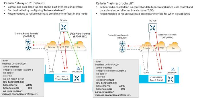
American GasCo deployed a segmented LAN design that included 3 VPNs to isolate the Forecourt, Convenience Store, and Video/IoT devices and users from each other. With SD-WAN, VPN segmentation of routes and traffic is automatically extended across the WAN to the hub WAN Edge routers due to the existence of VPN labels in the encapsulation. VPN segmentation was further extended into the data center by interconnecting the WAN Edge routers to the distribution routers with VLAN trunks which were mapped into VRFs 1-3 to maintain segmentation all the way to the per-VRF access switches connecting to the server farms in each VPN.
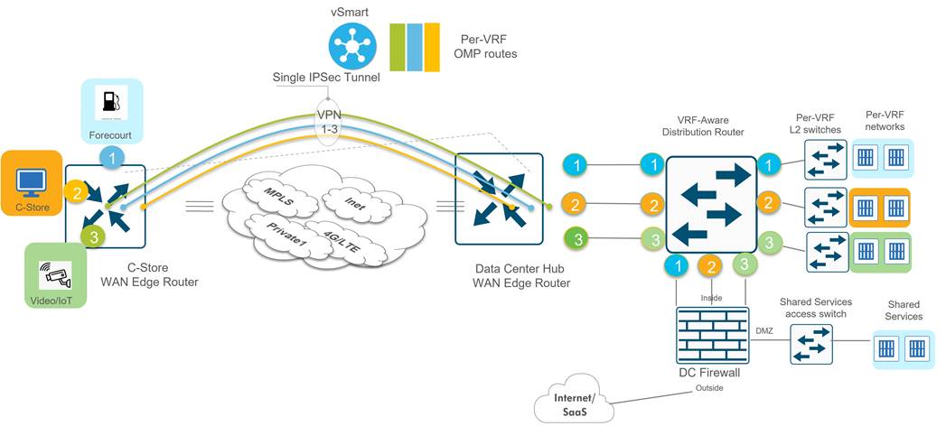
SD-WAN Overlay Routing Across the Transports
Cisco Catalyst SD-WAN supports numerous methods of mapping application traffic onto the available transports at a site. These methods can be implemented on a per-VPN basis, depending on the application requirements and business intent.
● Per-session active-active load sharing across multiple transports
● Per-session active-active weighted load sharing across multiple transports where configured ratios are applied for proportional traffic distribution across transports with disproportionate bandwidth
● Active/standby forwarding for pinning application traffic to specific transports
● Application-aware routing where the transport selection occurs after tunnel performance measurements are taken and an applications tolerance for loss/jitter/latency is considered from a pre-determined SLA
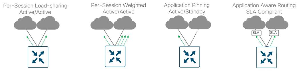
American GasCo chose an active/active design for all VPNs, with per-session load sharing possible across all available transports. This was achieved by keeping the tunnel preferences for all transports at their default values (preference 0). Application-aware routing was additionally deployed for performance-based forwarding of critical application traffic.
Overlay IP Unicast Routing Design
This section focuses on the routing from branch to data center over the overlay, which includes the redistribution of routing protocols into and out of OMP.
Branch routing
American GasCo branch WAN Edge routers were deployed as Layer 2 LAN sites for each service VPN since no other L3 routers or firewalls were present at the stores.
● Switched virtual interfaces (SVIs) for each service VPN were provisioned with addresses allocated from the VPN space assigned to each site.
● The prefixes associated with these SVI addresses are considered “directly-connected routes” and automatically advertised to the SD-WAN Controller in OMP.
● The control policy “TO-SPOKES” restricts the OMP routes sent to store (spoke) routers to the TLOC and service VPN routes associated with the data center site IDs. OMP routes associated with other store (spoke) router site-ids are filtered. This results in BFD/IPsec tunnels only being formed between the spokes and hubs, with spoke routers receiving only the service VPN routes of the data center (hub) sites.
The following diagram illustrates branch routes being advertised into OMP. The routes are received by the SD-WAN Controllers and advertised to the data center routers. The control policy “TO-SPOKES” prevents branch 1’s TLOCs from being advertised to other branches.
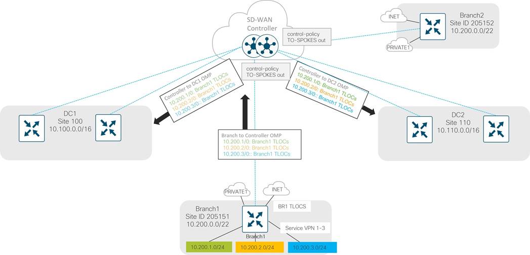
Data Center Routing
Parts of the data center routing design were described in the data center design section. The following was covered:
● The core routers in each DC run OSPF and send prefixes from the opposite DC toward the distribution routers.
● Since the DCI circuit is also the intended to be used as an alternative path in the event of a complete failure of WAN Edge routers in either DC, it is necessary for each WAN Edge router in both data centers to announce the prefixes associated with the other DC in addition to their own and the default route.
● Since the Data Center Interconnect (DCI) circuit between each DC is the intended path for all inter-DC traffic, the control policy “TO-HUBS” was modified to prevent SD-WAN Controller advertisements from one DC to the other over the SD-WAN overlay.
● The distribution routers run OSPF on each VPN toward the core and redistributes BGP to OSPF.
● The distribution routers run BGP on each VPN toward the WAN Edge routers. Network statements are used in BGP to advertise the following prefixes to the WAN Edge routers:
◦ 0.0.0.0/0 (default route)
◦ 10.0.0.0/8 (overlay summary)
◦ 10.100.0.0/16 (DC1 prefix)
◦ 10.110.0.0/16 (DC2 prefix)
Other details of the data center WAN Edge routing design to/from the overlay include:
1. Redistribution of OMP to BGP is enabled to announce the branch routes towards the distribution routers in each VPN
2. Local policy sets the BGP community attributes on the outbound announcements to the distribution routers to a unique value associated with OMP learned routes
3. Local policy drops any learned routes with this same BGP community on the inbound announcements of ,the distribution routers (to prevent loops)
4. Redistribution of BGP to OMP is enabled to propagate the data center prefixes and default route to the other branch sites.
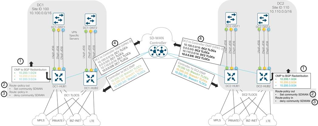
SD-WAN Controller Overlay Routing
From each WAN Edge router, TLOC routes and service-side routes are sent to the SD-WAN Controllers. In turn, the SD-WAN Controllers distribute these routes to other WAN Edge routers in the network. By default, the SD-WAN Controller router advertises the 4 best, equal-cost paths to the WAN Edge routers.
The diagram below shows an example of the default route being advertised from each data center from both WAN Edge routers over each TLOC. 8 default route paths are advertised from each data center, for a total of 16 default route paths, but only 4 total best, equal-cost paths are advertised to each WAN Edge spoke router from each SD-WAN Controller. In the example below, all 4 TLOCs from DC1 Edge 1 were advertised as next hops for the default route.
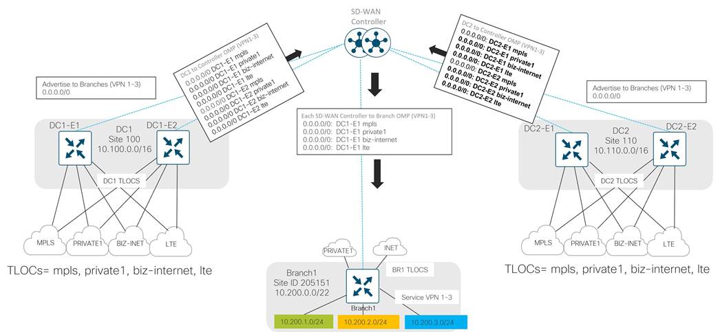
Ideally, TLOCs from all DC WAN Edge routers should be seen as paths to the Internet. American GasCo increased the SD-WAN Controller OMP parameter send-path-limit CLI (or Number of Paths Advertised per Prefix in the SD-WAN Controller OMP feature template) to the maximum of 16, so additional equal-cost paths per prefix could be advertised to the WAN Edge routers.
| Tech Tip |
| By default, the SD-WAN Controller advertises the four best paths per prefix to the WAN Edge routers, and this can be modified by increasing the SD-WAN Controller OMP parameter send-path-limit CLI (or Number of Paths Advertised per Prefix in the SD-WAN Controller OMP feature template) to the maximum of 16. In addition, the WAN Edge router installs only 4 equal-cost, best paths in its forwarding table by default. To increase this number, use the ecmp-limit OMP CLI or feature template parameter on the WAN Edge router to change the number to a maximum of 16. |
The following diagram illustrates this change:
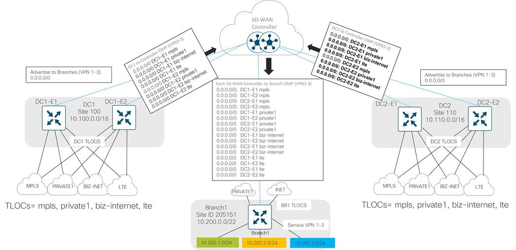
DC Preference Control Policy
Each data center site advertises similar routes since both centers can back up each other through the DCI link between them. If DC1 users need to reach the Internet exit, but the local exit is down, the default route can be followed through the DCI link to DC2 where the Internet exit there can be used.
Because the same routes are advertised out both data centers from each DC WAN Edge router over each TLOC, branches install several equal cost paths to DC1, DC2, and the Internet through both data centers (up to 16, depending on the WAN Edge OMP ecmp-limit settings)! American GasCo desired more deterministic routing behavior, so the current control policy was modified so the appropriate DC is preferred depending on the route but the same route from the other DC will still be advertised for backup purposes.
Table 17. DC Preference Control Policy
| SD-WAN Controller Custom Control Policy Name |
Description |
SD-WAN Controller Logic |
Policy Applied to Site Lists |
Direction Policy Applied on SD-WAN Controller |
| TO-SPOKES |
Set DC preference on various routes sourced from the DCs. |
Set higher preference for DC2 LAN routes coming from DC2 site-id Set lower preference for DC1 LAN routes coming from DC2 site-id Set higher preference for all other routes coming from DC1 site-id |
All branches |
Outgoing |
The DC preference control policy is illustrated in the following diagram:
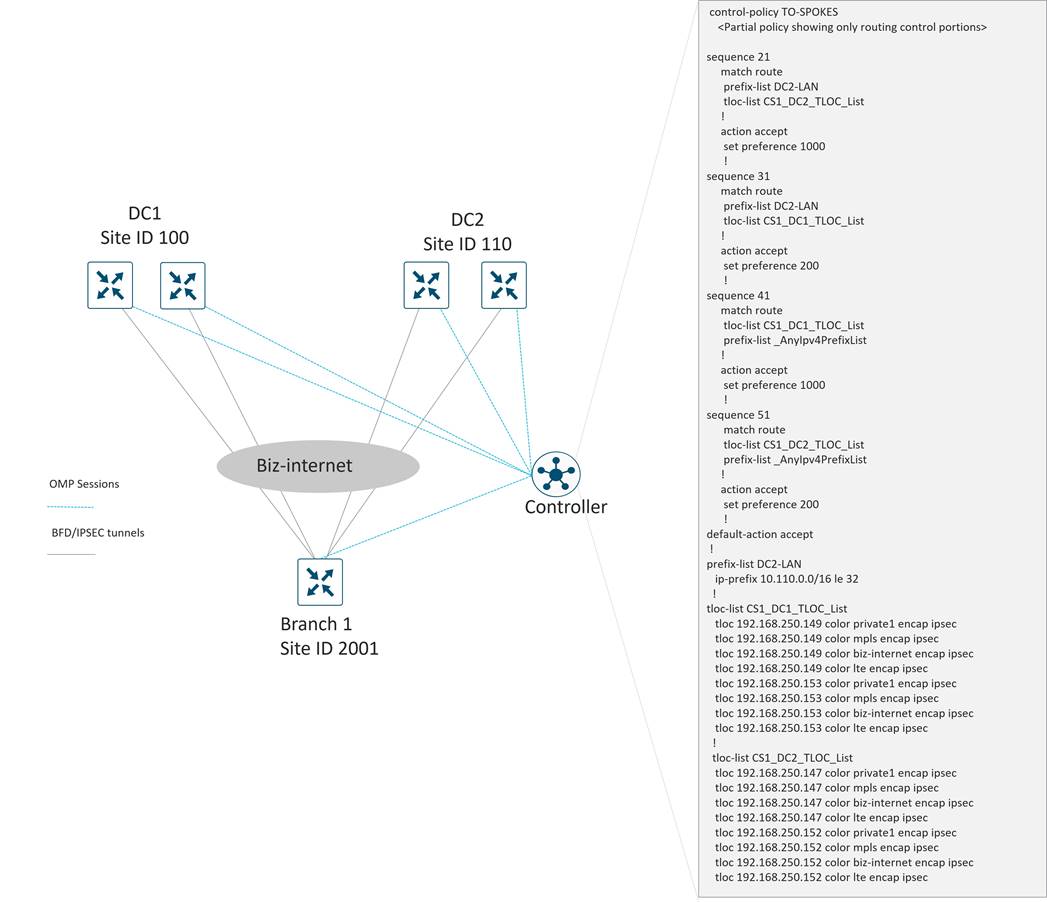
See Appendix A for the full control policy configuration, which incorporates hub-and-spoke policy and DC route preferences into one policy for the branches.
| Tech Tip |
| By default, OMP only advertises the best route or routes in the case of equal-cost paths. It is recommended that the send-backup-paths OMP parameter is enabled on the SD-WAN Controller, so OMP advertises additional valid paths that do not qualify as the best paths for a given prefix. In addition to improving convergence, this allows the WAN Edge router to make the best path decision which may also be based on TLOC availability. |
American GasCo uses the send-backup-paths OMP parameter, so the WAN Edge routers receive the primary and backup TLOCs for each prefix. The following diagram illustrates this:
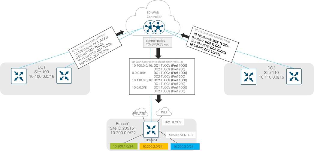
*Note that in the diagram, the shortcut, DC1 TLOCs, represents all DC1-Edge 1 and DC1-Edge 2 TLOCs (mpls, private1, biz-internet, and lte), for a total of 8 paths.
Summary
The American GasCo IP unicast routing design that relates directly to the overlay is depicted in the following diagram. DC-to-DC routing is also shown.
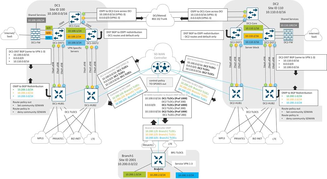
IP multicast is a method of sending IP application datagrams to groups of interested receivers in a single transmission. It is a technique for one-to-many and many-to-many real-time communication over an IP infrastructure that scales to a larger receiver population by requiring neither prior knowledge of a receiver’s identity nor prior knowledge of the number of receivers. Multicast is considered a bandwidth-conserving technology in that it requires the application source to send a packet only once, even if it needs to be delivered to many receivers. The nodes in the network take care of replicating the packet to reach multiple receivers such that messages are sent over each link of the network only once.
Examples of multicast applications typically found in wide area network environments include video conferencing, news distribution, software distribution and database replication. With these ‘one-to-many’ applications, the multicast sources are located at central sites such as data centers and sent to receivers at multiple locations. In a hub and spoke overlay WAN topology such as SD-WAN, the hub routers replicate the multicast traffic and send to remote site routers with receivers that have requested the stream through IGMP messaging. The benefits of multicast bandwidth reduction with these applications are not fully realized until two or more receivers at a remote site request the same streams.
American GasCo was interested in multicast for efficient delivery of IP video surveillance traffic captured at their stores to multiple monitoring and recording locations across the WAN. With this application, each IP video camera at a store is a multicast source that would send traffic to a multicast group address, which is more efficient than sending multiple IP unicast copies to different monitoring and recording destinations. This is an example of a many-to-many multicast application where the sources are located at remote sites where bandwidth is expensive, and IP multicast can provide significant value in reducing traffic. To justify the use case for multicast, it was necessary to fully understand the IP video surveillance system application and traffic flows as described in the following section.
IP Video Surveillance System Infrastructure
American GasCo deployed a next generation IP video surveillance infrastructure to overhaul existing CCTV systems to monitor the gas station forecourt and convenience store areas for safety and loss protection. This was a distributed architecture that included different components to monitor along with store-recorded surveillance data.
Branch
IP Video surveillance equipment provided by the vendor to each store included the video cameras, network video recorders (NVRs) and an industrial ethernet switch to connect the outdoor cameras.
● Ruggedized outdoor cameras with wide-angle lenses and very high resolution for monitoring parking lot and pump areas
● Indoor cameras with zoom capabilities to monitor the convenience store entry/exit areas, cash registers and merchandise
● Local Network Video Recorders (NVR) for camera setup, management, and file storage. Local NVRs can function as media servers to send station streams to centralized NVRs and monitoring stations
● Industrial Ethernet switch suitable for outdoor installation.
Corporate Security Operation Center
American GasCo operates a corporate security operation center (SOC) that is part of the network operations center located at the primary data center in Atlanta. The corporate SOC is staffed by operators who manage the entire infrastructure and coordinate with regional monitoring centers for incident response. The infrastructure in the DC includes:
● Network Video Recorder (NVR) farms for centralized storage of video from all locations.
● Video wall comprised of multiple monitors displaying details of outages, significant alarms, ongoing incidents, weather, and other conditions that may affect video surveillance
● PCs for incident reporting with monitoring and remote-control camera capabilities
● IP Phones in a call center for incident coordination
● Indoor and outdoor cameras for surveillance of the data center itself
Regional Security Operation Centers (SOC)
A number of small security operation centers (SOC) were designated to provide real time security monitoring and coordination with first responders for stores within a regional geographic area. These could be located at American GasCo owned locations or at 3rd party locations with contracted security operators monitoring the feeds.
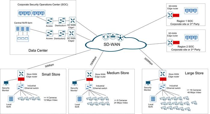
Understanding IP Video traffic flows
Planning the bandwidth requirements of an IP video surveillance project is among the most critical design steps, similar in importance to placing and connecting the cameras. Without careful planning, the surveillance system might end up creating bandwidth bottlenecks that could impact the quality of the video streams being monitored, inhibit recording of critical incidents, and in extreme cases, affect other critical applications such as point-of-sales transactions. For bandwidth planning purposes at each site, American GasCo allocated up to 3 Mbps per video camera. This allows for high resolution of the video streams and lossless compression of data being stored on the NVRs. The network traffic generated by IP video surveillance includes the following streams:
● LAN traffic from realtime camera feeds to the monitoring PCs in the store
● LAN traffic from video files sent to the local NVR for storage
● WAN traffic from realtime camera feeds to the video wall monitoring PCs in the corporate SOC
● WAN traffic from video files sent to the centralized NVR farm storage in the DC
● WAN traffic from realtime camera feeds to the PCs in the regional SOC
IP Multicast for American GasCo Video Surveillance
By enabling IP multicast on cameras and across the WAN, American GasCo was able to enable each camera as a multicast source, which reduced WAN traffic on the remote transport circuits by up to 50%. Multicast feeds from each camera at a site were streamed to a multicast group address that would be subscribed to by interested receivers in the corporate NOC in the data center and also the regional SOC responsible for remote monitoring. This traffic could be sent one time from the branch router to multicast replicators at the hubs where it could be replicated to tunnels to the remote SOCs, effectively reducing WAN traffic by 50%.
Cisco Catalyst SD-WAN Overlay Multicast Overview
All Cisco Catalyst SD-WAN Edge routers configured for multicast must be designated as either replicators or non-replicators. WAN Edge routers designated as "non-replicators" encapsulate multicast traffic into SD-WAN tunnels and forward to WAN Edge routers designated as "replicators". Replicators send copies of the original packet stream over separate SD-WAN tunnels to multicast receivers located at remote sites. Cisco Catalyst SD-WAN overlay multicast supports PIM version 2 with some restrictions.
On the service side, the SD-WAN software supports native multicast. A WAN Edge router appears as a native PIM router and establishes PIM neighborship with other PIM routers at a local site where they exist.
Receivers residing downstream of a WAN router can join multicast streams by exchanging IGMP membership reports directly with the device, and no other routers are required. This applies only to sites that have no requirement for supporting local sources or PIM-SM rendezvous points.
On the transport side, PIM-enabled WAN Edge routers originate multicast service routes (called multicast auto-discover routes), sending them via OMP to the SD-WAN Controllers. The multicast "auto-discover routes" indicate whether the router has PIM enabled and whether it is a replicator. If the router is a replicator and the load threshold has been configured, this information is also included in the multicast auto-discover routes.
Each PIM router also conveys information learned from the PIM join messages sent by local-site multicast-enabled routers, including multicast group state, source information, and RPs. These routes assist WAN Edge routers in performing optimized joins across the overlay when joining existing multicast sources.
A Cisco Catalyst SD-WAN Edge router can function as a PIM Rendezvous Point (RP), but as of IOS-XE 17.6, it cannot be configured as an "anycast RP" due to current lack of support for MSDP.
A Cisco Catalyst SD-WAN Edge router be configured with static group-to-rp mappings, or leverage BSR or auto-rp to learn them dynamically.
American GasCo SD-WAN Multicast Design
Group addressing
American GasCo designed their multicast group addressing around the bandwidth standards for each site, where a channel would be associated with video encoding rate translating to low, medium or high bandwidth rates of each station. Addresses were drawn out of the space reserved by IANA for private multicast addresses, in the range 239.0.0.0-239.255.255.255
● 239.0.1.1: Type 1 sites
● 239.1.1.1: Type 2 sites
● 239.2.1.1: Type 3 and Type 4 sites
PIM Rendezvous points (RPs)
American GasCo had an existing PIM-SM multicast deployment on their legacy network that included PIM RPs in the primary data center distribution routers that were re-used for the SD-WAN multicast deployment. The two RPs were configured with the same ‘anycast RP’ address and peered with MSDP so that either could function as the RP for receivers and sources in the network, providing a degree of load-sharing and high availability should either fail. Each WAN Edge was configured with static group-to-rp mappings to this Anycast RP address for all multicast groups.
Replicators
The branch routers at the remote sites were configured as non-replicators and the Catalyst 8500 WAN Edge routers in the data centers were configured as replicators.
The American GasCo SD-WAN multicast deployment is shown in the following diagram.
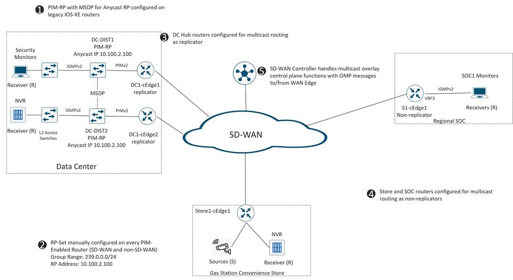
See Appendix B for details of the SD-WAN multicast configurations.
Quality of service (QoS) refers to mechanisms and features that manage data traffic to reduce packet loss, latency and jitter on a network that are typically associated with congested links or circuits. QoS is especially beneficial on branch WAN edge routers, where bandwidth is scarce as compared to the data center and transport provider networks which are typically over-engineered to avoid bottlenecks that would cause congestion. The Cisco Catalyst SD-WAN QoS toolkit includes several purpose-built features designed for overlay networks that can be used in addition to the traditional classification, marking, scheduling, queueing features associated with routed networks.
How QoS Works
The QoS feature chain on the Cisco IOS XE SD-WAN devices starts by examining packets entering at the edge of the network. With localized policy access-lists or centralized SD-WAN Controller data policies, you can provision QoS to classify incoming data packets into multiple forwarding classes based on importance, spread the classes across different interface queues, and schedule the transmission rate level for each queue. To provision QoS, you must configure each router in the network. Generally, each router on the local service-side network examines the QoS settings of the packets that enter it, determines which class of packets are transmitted first, and processes the transmission based on those settings.
Classify Data Packets
You can classify incoming traffic by associating each packet with a forwarding class. Forwarding classes group data packets for transmission to their destination. Based on the forwarding class, you assign packets to output queues. The routers service the output queues according to the associated forwarding, scheduling, and rewriting policies you configure.
Schedule Data Packets
You can configure a QoS map for each output queue to specify the bandwidth. This enables you to determine how to prioritize data packets for transmission to the destination. Depending on the priority of the traffic, you can assign packets higher or lower bandwidth. Based on the conditions defined in the QoS map, packets are forwarded to the next hop.
Interfaces on Cisco IOS XE SD-WAN devices, have eight queues, which are numbered 0 to 7. Queue 0 is reserved and is used for both control traffic and low-latency queuing (LLQ) traffic. For LLQ, any class that is mapped to queue 0 must also be configured to use LLQ. Queues 1 to 7 are available for data traffic, and the default scheduling for these seven queues is weighted round-robin (WRR). For these queues, you can define the weighting according to the needs of your network. When QoS is not configured for data traffic, queue 2 is the default queue.
Rewrite Data Packets
You can configure and apply rewrite rules on the egress interface to overwrite the Differentiated Services Code Point (DSCP) value for packets entering the service provider network. Rewrite rules allow you to map traffic to different code points when the traffic exits the system to comply with code points supported by the receiving service provider devices.
Traffic Shaping
You can configure shaping to control the maximum rate of traffic sent. You can configure the aggregate traffic rate on an interface to be less than the line rate so that the interface transmits less traffic than it is capable of transmitting. You can apply shaping to outbound interface traffic.
An illustration of the input and output feature chain of basic SD-WAN QoS components follows:
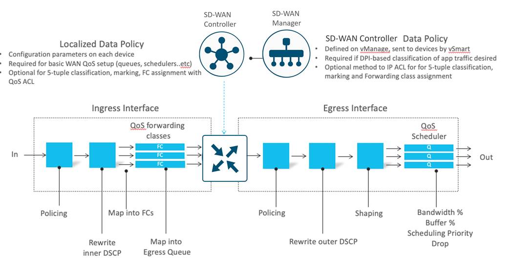
American GasCo SD-WAN QoS Design
QoS Network Objectives
The American GasCo network objectives for deploying QoS policies included the following:
● Guaranteeing voice quality meets enterprise standards
● Ensuring a high Quality of Experience for monitoring and recording IP video surveillance data
● Ensuring IP Video cameras do not consume too much bandwidth
● Identifying and de-prioritizing non-business applications
● Improving user productivity by minimizing network response times to Microsoft SaaS applications
● Improving network availability by protecting the control plane
Enterprise QoS Architecture
American GasCo adopted Cisco’s implementation of the RFC 4594 QoS recommendations for the classification, marking, queuing, and dropping of their applications. The following table summarizes these recommendations, including guidance for whether an application class should be considered as business relevant, irrelevant, or default.
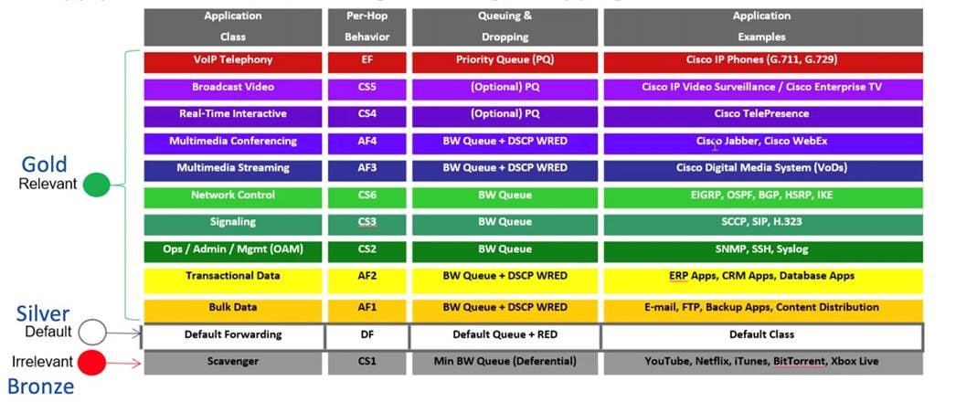
American GasCo aggregated the 12 enterprise application classes into an 8-class forwarding model that would be implemented on their WAN Edge routers. With help from the application discovery audit, American GasCo mapped their current and future applications to forwarding classes based on their characteristics and knowledge of business relevance.
Table 18. American GasCo 8-Class Forwarding Model
| QoS Forwarding Class |
DSCP/TOS |
Queuing |
Drop Type |
American GasCo Applications |
| VOICE |
EF/46 |
Priority Queue (PQ) |
Tail |
IP telephony |
| CRITICAL DATA |
AF21/18 |
WRR |
RED |
Forecourt fuel control, Pump POS, C-Store POS |
| INTERACTIVE VIDEO |
AF41/34 |
WRR |
RED |
Video conferencing kiosks on the gas pumps (future) |
| NETWORK CONTROL |
CS6/48 |
WRR |
RED |
SD-WAN protocols (BFD, OMP, Netconf), IP Routing protocols (BGP, OSPF) |
| STREAMING VIDEO |
AF31/26 |
Priority Queue (PQ) |
Tail |
IP video surveillance |
| CALL SIGNALING |
CS3/24 |
WRR |
RED |
VoIP and video signaling |
| DEFAULT |
0 |
WRR |
RED |
General browsing, software updates |
| SCAVENGER |
CS1/8 |
WRR |
RED |
Social media apps, gaming apps, Streaming services, Netflix, Hulu |
Based on this architecture, the QoS design was implemented through device configurations and policies. The following sections describe the detailed QoS design for the branch and data center WAN Edge routers.
WAN Edge Router QoS Feature Summary
● QoS Map Policy defining 8 forwarding classes and their associated router queue mapping, bandwidth/buffer percentages, scheduling and drop algorithms
● Per-Tunnel traffic-shaping to control traffic rates across tunnels between data center and remote site WAN Edge routers
● Adaptive QoS traffic shaping for branch sites with Cellular 4G/LTE transports to account for bandwidth fluctuations of LTE networks
● Centralized SD-WAN Controller Data Policy for traffic classification, marking and assignment to a forwarding class at the branch
● Localized Data Policy for traffic classification, marking and assignment to a forwarding class at the data center
QoS Map Policies
QoS Maps are local policies that define parameters such as the bandwidth and buffer percentage, and the scheduling and packet-drop types for each queue. These are associated with WAN transport interfaces where the aggregate shaping rates can be specified.
Following the recommendations in RFC 4594, American GasCo developed the QoS-Map policy named ‘WAN-QOS-MAP’ that would be applied to all Ethernet-connected WAN transport interfaces.
Table 19. WAN-QOS-MAP Policy
| Bandwidth % |
LLQ Policing % |
Scheduling Type |
Drop Type |
Forwarding Class |
|
| 0 |
|
10 |
Low Latency Queue (LLQ) Priority 1 Policer |
Tail |
CONTROL |
| 1 |
25 |
|
Bandwidth Queue Weighted Round Robin (WRR) |
Random Early |
CRITICAL DATA |
| 2 |
15 |
|
Bandwidth Queue Weighted Round Robin (WRR) |
Random Early |
DEFAULT |
| 3 |
1 |
|
Bandwidth Queue Weighted Round Robin (WRR) |
Random Early |
SCAVENGER |
| 4 |
10 |
|
Bandwidth Queue Weighted Round Robin (WRR) |
Random Early |
INTERACTIVE |
| 5 |
5 |
|
Bandwidth Queue Weighted Round Robin (WRR) |
Random Early |
BULK DATA |
| 6 |
|
30 |
Low Latency Queue (LLQ) Priority 2 Policer |
Tail |
STREAMING VIDEO |
| 7 |
4 |
|
Bandwidth Queue Weighted Round Robin (WRR) |
Random Early |
CALL SIGNALING |
A second QoS policy “LTE-WAN-QOS-MAP” was defined specifically for cellular 4G/LTE interfaces, where American GasCo desired to restrict IP video traffic on LTE interfaces. This policy included aggressive policing of the STREAMING_VIDEO forwarding class and allocated additional bandwidth to the CRITICAL_DATA forwarding class associated with point-of-sale and forecourt applications.
Table 20. LTE-QOS-MAP Policy
| Queue |
Bandwidth % |
LLQ Policing % |
Scheduling Type |
Drop Type |
Forwarding Class |
| 0 |
|
10 |
Low Latency Queue (LLQ) priority 1 policer |
Tail |
CONTROL |
| 1 |
50 |
|
Bandwidth Queue Weighted Round Robin (WRR) |
Random Early |
CRITICAL DATA |
| 2 |
15 |
|
Bandwidth Queue Weighted Round Robin (WRR) |
Random Early |
DEFAULT |
| 3 |
1 |
|
Bandwidth Queue Weighted Round Robin (WRR) |
Random Early |
SCAVENGER |
| 4 |
10 |
|
Bandwidth Queue Weighted Round Robin (WRR) |
Random Early |
INTERACTIVE VIDEO |
| 5 |
5 |
|
Bandwidth Queue Weighted Round Robin (WRR) |
Random Early |
BULK DATA |
| 6 |
|
1 |
Low Latency Queue (LLQ) priority 2 policer |
Tail |
STREAMING VIDEO |
| 7 |
4 |
|
Bandwidth Queue Weighted Round Robin (WRR) |
Random Early |
CALL SIGNALING |
Per-Tunnel QoS
Per-tunnel QoS was implemented to allow granular traffic shaping on the data traffic sent over the IPsec tunnels from the hub routers in the data centers to each branch router. Per-tunnel QoS solves the problem in hub-and-spoke overlay networks where traffic sent at high rates over high bandwidth transport circuits of hub sites can overwhelm the receive bandwidth capacities of lower bandwidth spoke circuits at branches. Per-tunnel QoS uses OMP to announce the receive bandwidth capacities of each remote router to the hub routers that provide the shaping on the appropriate tunnel. Per-tunnel QoS was introduced in 20.1/16.12 control component/IOS XE SD-WAN code version). An explanation of the feature benefits is provided below.
Before the introduction of Per-tunnel QoS feature on Cisco Catalyst SD-WAN, QoS on a hub could be configured to measure only the aggregate outbound traffic for all spokes. Per-tunnel QoS for Cisco Catalyst SD-WAN provides the following benefits.
● A QoS policy provides the capability of regulating traffic from hub to spokes at a per-spoke level.
● The hub cannot send excessive traffic to a small spoke and overrun it.
● The maximum outbound bandwidth and QoS queue are set up automatically on the hub when each spoke registers with an Overlay Management Protocol (OMP) message.
● The amount of outbound hub bandwidth that a “greedy” spoke can consume can be limited; therefore, the traffic cannot monopolize a hub’s resources and starve other spokes.
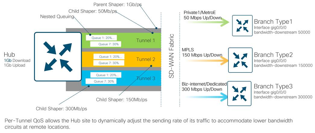
Adaptive QoS for LTE interfaces
Per-Tunnel QoS works effectively when deployed on WAN transport providers such as MPLS or Metro Ethernet with service level agreements (SLAs) for upstream and downstream bandwidth guarantees. This is not often the case with broadband Internet or LTE transports where the available bandwidth at a given time can change dynamically based on subscriber usage or even changing weather conditions. This minimizes the benefits of Per-Tunnel QoS since the bandwidth configurations on spoke routers may be inaccurate during these periods causing the hub router to shape too much traffic or not enough. Adaptive QoS is an enhancement to Per-tunnel QoS for branch routers which adjusts the WAN interface shaper for outbound traffic and also the Per-Tunnel QoS shaper on the hub router for inbound. It does this by monitoring WAN circuits for loss in both directions and notifying the SD-WAN Controllers through OMP messaging.
● With adaptive QoS, the shapers at the remote site WAN edge (interface shaper and per-tunnel shaper) are dynamic in nature and can adapt to the available WAN bandwidth based on loss detected in the upstream or downstream directions.
● Adaptive QoS can be enabled through the SD-WAN Manager on a specific interface of an Edge device that is configured with the spoke role in a hub-to-spoke network topology.
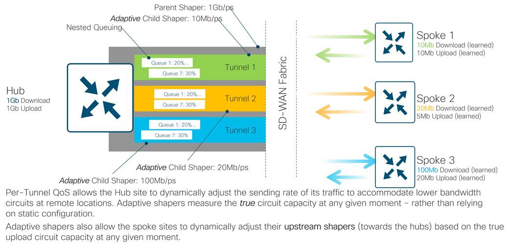
American GasCo deployed adaptive QoS for their remote site WAN edge routers with broadband internet and cellular/LTE transports. This included the integrated cellular interfaces of the ISR1100-LTE routers and on ethernet interfaces connected to cellular LTE modems.
American GasCo store managers were given the option to utilize data plans from any of the major 4G LTE carriers so that they could choose the provider with best coverage in their area. With adaptive QoS, configurations for the upstream and downstream min/max and default values must be provided so that shapers will be adjusted to provide the maximum throughput before drops are observed. These values were obtained from the service providers and verified by American GasCo at several of their sites with Internet speed testing.
● The 4G LTE carriers advertised a range of 14-61 Mbps of download bandwidth and upload speeds of 3–14 Mbps on average and these values were used to derive the min and max kbps shaping rates for adaptive QoS on the interfaces.
Classification and Marking
The classification, marking and forwarding class/queue assignment functions on an SD-WAN edge router can be implemented through access-list configurations in a localized data policy or from centralized data policies from the SD-WAN Controllers.
● With localized data policies, traffic can be classified only on the bases of 5-tuple matches in the packet headers.
● With centralized data policy, traffic can be classified on the basis 5-tuple matches in the packet headers and also from deep packet inspection application signatures in the packet payload.
American GasCo was able to use localized data polices on their data center WAN Edge routers, since application classification and marking was performed on the distribution routers, which were considered trusted. Centralized SD-WAN Controller data polices were created for the branch routers that were required to classify traffic destined to the data center applications and also to the Internet, which would require NBAR/DPI (Network Based Application recognition/deep packet inspection.
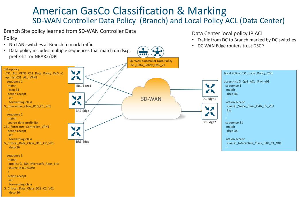
See Appendix C for details of the SD-WAN QoS configurations.
Application-Aware Routing (AAR)
Application-Aware Routing (AAR) provides a traffic-engineering framework that considers real-time performance data and pre-defined SLAs when determining which SD-WAN tunnel flows associated with a particular application class should be placed on. Application aware routing uses performance data collected from the BFD probes sent across SD-WAN tunnels to determine as measurements across each tunnel in order to keep real-time performance measurements of SD-WAN tunnels.
Application-Aware Routing additionally allows the network administrator to set a preferred path as long as the SLAs are satisfied and (optionally) a backup preferred path in situations where no available WAN transports meet the specified SLA.
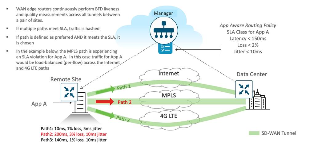
Cisco Catalyst SD-WAN Application-Aware Routing consists of three components:
● Identification
● Defining the SLA requirements
● Application-Aware Routing Policy
Identification
Classify the traffic / Application group of interest. Similar to QoS, AAR can classify traffic on the basis 5 tuple matches in the packet headers and also from deep packet inspection application signatures in the packet payload. AAR can also match based on additional criteria defined in policy lists to include:
Table 21. AAR Matching Criteria
| List Type |
Groups of Interest |
| Cloud SaaS Application List |
Leverage the pre-defined Cloud-SaaS Application list |
| DNS Application List |
Used when split DNS lookup for certain applications is required |
| DNS |
DNS lookup (DNS request / response) packets can be matched |
| DSCP |
Pre-configured traffic with DSCP values, through QoS policy on the service-side traffic, can be leveraged |
| PLP |
Pre-configured traffic part of the Packet Loss Priority (PLP) queue, configured part of QoS policy, can be matched |
| Protocol |
Traffic with certain protocol number |
| Source Data Prefix |
Pre-defined custom data-prefix of the traffic |
| Source Port |
Data traffic with defined port number |
| Destination Data Prefix |
Pre-defined custom data-prefix of the traffic |
| Destination Port |
Data traffic with defined port number |
Defining the Application SLA requirements
The Service Level Agreement specifics the network path characteristics (loss, latency, and jitter) that the application can handle for optimized performance.
The SD-WAN Manager centralized policy wizard provides network administrator options to define custom Service Level Agreement (SLA) or leverage the pre-defined SLAs as shown below:
Table 22. Application SLA Definitions
| Name |
Loss % |
Latency (msec) |
Jitter (msec) |
| Transactional-Data |
5 |
50 |
100 |
| Bulk-Data |
10 |
300 |
100 |
| Voice-And-Video |
2 |
45 |
100 |
| Default |
25 |
300 |
100 |
Application-Aware Routing Policy
The AAR Policy maps the classified traffic to the transport tunnel based on the defined SLA requirement. The Application-Aware Routing policy defined in the SD-WAN Manager binds the selected application/traffic list with the SLA. For all matched data-traffic traversing from the LAN/Service side to remote sites through the device WAN transports, the AAR policy defines the following:
● Preferred Color – the selected data traffic is pinned to the chosen WAN transport(s) as long as the transport(s) meets the specified SLA
● Strict – if enabled, the selected data traffic would be dropped if any of the WAN transport(s) doesn’t meet the specified SLA
● Backup SLA Preferred Color – the selected data traffic is pinned to the chosen WAN transport(s) only when no transport(s) meets the specified SLA and Strict option is not enabled.
● Log – if enabled, a syslog message is generated first time a packet flow is logged and every 5 minutes thereafter, as long as the flow is active
American GasCo SD-WAN Application Aware Routing Design
The AAR design was built on top of the Enterprise 8-class QoS framework. American GasCo deployed 4 custom AAR SLA classes with the following parameters:
Table 23. American GasCo AAR SLA Classes
| AAR SLA Class |
Loss % |
Latency (msec) |
Jitter (msec) |
Fallback Best Tunnel Criteria |
Loss Variance % |
Latency Variance % |
Jitter Variance % |
| SLA_REALTIME |
2 |
300 |
60 |
Loss-latency-jitter |
10 |
100 |
10 |
| SLA_VIDEO |
2 |
600 |
60 |
Loss-jitter-latency |
2 |
100 |
10 |
| SLA_BUSINESS_DATA |
2 |
400 |
100 |
Latency |
- |
100 |
- |
| Default |
5 |
800 |
100 |
Unspecified |
- |
- |
- |
SLA Class Notes:
● BFD measurements reflect round-trip loss, latency and jitter characteristics across SD-WAN tunnels.
● Fallback best tunnel criteria (optionally) allows administrators to specify the order of importance per SLA class when deciding which tunnel is the ‘next best’ when an SLA violation affects a preferred tunnel.
● Loss, Latency, and jitter variance % allow administrators to specify a range of values where SLA measurements would be considered ‘equal’ when attempting to select a fallback tunnel. For example, a latency variance of 10% would treat a pair of tunnels with 50 ms and 54 ms as being same with respect to latency, and AAR would move on to the next SLA criteria to select the preferred path
The AAR Policy was then defined to classify applications into AAR SLA classes based on DSCP matching, and to specific how traffic should be forwarded when tunnel colors performance is determined to be in and out of SLA.
Table 24. American GasCo AAR Policy
| American GasCo Applications |
AAR SLA Class |
TOS Match |
Preferred Color(s) |
SLA Not Met Behavior |
Backup SLA Preferred Color |
| IP telephony |
SLA_REALTIME |
46 |
mpls, private1 |
Load balance |
Biz-internet |
| Video surveillance |
SLA_VIDEO |
26 |
mpls, private1 |
Load balance |
Biz-internet |
| FCC, POS, 0365 |
SLA_BUSINESS_DATA |
18 |
mpls, private1 |
Load balance |
None |
| All others |
Default |
All others |
biz-internet, public-internet |
Load balance |
None |
See Appendix D for details of the SD-WAN AAR configurations.
While completing the detailed design, American GasCo moved to a pilot phase at several stores where they evaluated the SD-WAN use cases and performance of their existing and new applications across each WAN transport type. To prepare for the pilot, American GasCo installed the Catalyst 8500 hub routers in each data center and onboarded them with the control components that had been previously instantiated in AWS by Cisco Cloud operations. This provided their network operations team an opportunity to test their OSS and NMS system integrations and develop procedures for new equipment installations and onboarding. The pilot also gave Cisco Cloud operations an estimate of the volume of application statistics that the SD-WAN Manager would be expected to receive once the network was fully deployed and allowed them to adjust settings in the statistics database volume sizes for alarms that were or were not needed for their use cases.
By following a structured methodology of planning and design, American GasCo was able to reduce risks and achieve the business objectives they had hoped for during the first phase of their SD-WAN deployment. The additional bandwidth brought to each store by the new private and public transport types provided noticeable performance improvements and increased site reliability and uptime. The flexibility to utilize any transport type available at a location removed the dependence on MPLS which reduced operating costs. The simplicity of SD-WAN VPN segmentation reduced the operational burden of configuring site-specific access-control lists, improving security, and freeing up engineers to spend time on more strategic projects for the business.
Appendix A: SD-WAN Centralized SD-WAN Controller Control Policy
control-policy CS1_CP_HubSpoke_DC1_pref_v2
sequence 1
match tloc
site-list CS1_ALL-DC
!
action accept
!
sequence 11
match tloc
!
action reject
!
sequence 21
match route
prefix-list DC2-LAN
tloc-list CS1_DC2_TLOC_List
!
action accept
set
preference 1000
!
sequence 31
match route
prefix-list DC2-LAN
tloc-list CS1_DC1_TLOC_List
!
action accept
set
preference 200
!
sequence 41
match route
tloc-list CS1_DC1_TLOC_List
prefix-list _AnyIpv4PrefixList
!
action accept
set
preference 1000
!
default-action accept
control-policy CS1-Block-DC-TLOCS-and-Routes
sequence 1
match tloc
site-list CS1_ALL-DC
!
action reject
!
sequence 11
match route
site-list CS1_ALL-DC
prefix-list _AnyIpv4PrefixList
!
action reject
!
!
default-action accept
!
lists
prefix-list DC2-LAN
ip-prefix 10.110.0.0/16 le 32
!
site-list CS1_ALL-Branches
site-id 100000-500000
!
site-list CS1_ALL-DC
site-id 100
site-id 110
!
site-list CS1_ALL-Sites
site-id 100-500000
!
tloc-list CS1_DC1_TLOC_List
tloc 192.168.250.149 color private1 encap ipsec
tloc 192.168.250.149 color mpls encap ipsec
tloc 192.168.250.149 color biz-internet encap ipsec
tloc 192.168.250.149 color lte encap ipsec
tloc 192.168.250.153 color private1 encap ipsec
tloc 192.168.250.153 color mpls encap ipsec
tloc 192.168.250.153 color biz-internet encap ipsec
tloc 192.168.250.153 color lte encap ipsec
!
tloc-list CS1_DC2_TLOC_List
tloc 192.168.250.147 color private1 encap ipsec
tloc 192.168.250.147 color mpls encap ipsec
tloc 192.168.250.147 color biz-internet encap ipsec
tloc 192.168.250.147 color lte encap ipsec
tloc 192.168.250.152 color private1 encap ipsec
tloc 192.168.250.152 color mpls encap ipsec
tloc 192.168.250.152 color biz-internet encap ipsec
tloc 192.168.250.152 color lte encap ipsec
!
vpn-list CS1_ALL_VPNS
vpn 1-3
!
prefix-list _AnyIpv4PrefixList
ip-prefix 0.0.0.0/0 le 32
!
apply-policy
site-list CS1_ALL-DC
control-policy CS1-Block-DC-TLOCS-and-Routes out
!
site-list CS1_ALL-Branches
control-policy CS1_CP_HubSpoke_DC1_pref_v2 out
Appendix B: WAN Edge Multicast Configurations
Branch
● Multicast implemented in service VPN 3 only
● Includes static RP-mapping to 10.200.2.100, the anycast RP address configured on DC1-DIST1 and DC1-DIST2 in the data center
● Access-list “multicast-groups” implemented with a CLI add-on template:
“ip access-list standard multicast-groups
10 permit 239.0.0.0 0.255.255.255”
ip multicast-routing vrf 3 distributed
ip pim vrf 3 rp-address 10.100.2.100 multicast-groups
ip pim vrf 3 spt-threshold 0
ip access-list standard multicast-groups
10 permit 239.0.0.0 0.255.255.255
interface Vlan202
description VPN3 Surveillance VRF
vrf forwarding 3
ip address 10.220.0.1 255.255.255.0
ip pim sparse-mode
Datacenter
● DC router is multicast replicator
● All other configurations same as branch router
ip multicast-routing vrf 3 distributed multicast
address-family ipv4 vrf 3
replicator threshold 1000
ip pim vrf 3 rp-address 10.100.2.100 multicast-groups
ip pim vrf 3 spt-threshold 0
ip access-list standard multicast-groups
10 permit 239.0.0.0 0.255.255.255
interface GigabitEthernet0/0/0.112
description VRF3 to DIST1 router
encapsulation dot1Q 112
vrf forwarding 3
ip address 10.100.98.38 255.255.255.252
ip pim sparse-mode
!
interface GigabitEthernet0/0/1.118
description VRF3 to DIST2 router
encapsulation dot1Q 118
vrf forwarding 3
ip address 10.100.98.54 255.255.255.252
ip pim sparse-mode
Appendix C: WAN Edge QoS Configuration
Branch
Class-Map Configuration
● Forwarding class names based on RFC 4594 recommendations
class-map match-any VOICE_PQ_level1
match qos-group 0
!
class-map match-any CRITICAL_DATA
match qos-group 1
!
class-map match-any DEFAULT
match qos-group 2
!
class-map match-any SCAVENGER
match qos-group 3
!
class-map match-any INTERACTIVE
match qos-group 4
!
class-map match-any BULK
match qos-group 5
!
class-map match-any STREAMING_VIDEO
match qos-group 6
!
class-map match-any CALL_SIGNALING
match qos-group 7
Ethernet Policy-Map Configuration
● WAN-QOS-MAP is the local policy applied to Ethernet-connected WAN transports
● SD-WAN Manager 20.6 GUI provisions all queues as bandwidth queues except Queue0 which is designated as a priority queue
● For this design, American GasCo implemented a second priority queue for video with 30% PQ using CLI add-on template with following commands:
“policy-map WAN-QOS-MAP
class Queue6
no bandwidth remaining ratio 20
priority level 2
police rate percent 30”
policy-map WAN-QOS-MAP
class Queue0
police rate percent 10
!
priority level 1
!
class Queue1
bandwidth remaining ratio 25
random-detect precedence-based
!
class class-default
bandwidth remaining ratio 15
random-detect precedence-based
!
class Queue3
bandwidth remaining ratio 1
random-detect precedence-based
!
class Queue4
bandwidth remaining ratio 10
random-detect precedence-based
!
class Queue5
bandwidth remaining ratio 5
random-detect precedence-based
!
class Queue6
police rate percent 30
!
priority level 2
!
class Queue7
bandwidth remaining ratio 4
random-detect precedence-based
Per-Tunnel QoS
● Per-Tunnel QoS defined on all transports with Gigabit Ethernet interface handoff
● Bandwidth-downstream values communicated to Hub router via OMP to determine shaping value from hub to spoke
sdwan
interface GigabitEthernet0/0/0
tunnel-interface
encapsulation ipsec weight 1
no border
color private1 restrict
tunnel-qos spoke
bandwidth-downstream 50000
Hierarchical Service-Policy
● Hierarchical service-policy attached to Gigabit Ethernet interfaces which calls child WAN-QOS-MAP policy and derives shape average value from shaping rate parameter applied to the physical interface during provisioning
policy-map shape_GigabitEthernet0/0/0
class class-default
service-policy WAN-QOS-MAP
shape average 50000000
!
interface GigabitEthernet0/0/0
description private1
ip address 192.168.1.175 255.255.255.0
ip mtu 1500
service-policy output shape_GigabitEthernet0/0/0
LTE Service-Policy
● LTE-WAN-QOS-MAP is the local policy applied to cellular 4G/LTE WAN transports. This policy is the same as the WAN-QOS-MAP with the exception that Queue6 (video traffic) is policed down to 1% to preserve bandwidth for critical data applications.
● For this design, American GasCo implemented a second priority queue for video with 1% PQ using a CLI add-on template with the following commands:
“policy-map LTE-WAN-QOS-MAP
class Queue6
no bandwidth remaining ratio 20
priority level 2
police rate percent 1”
policy-map LTE-WAN-QOS-MAP
class Queue0
police rate percent 14
!
priority level 1
!
class Queue1
bandwidth remaining ratio 50
random-detect precedence-based
!
class class-default
bandwidth remaining ratio 15
random-detect precedence-based
!
class Queue3
bandwidth remaining ratio 1
random-detect precedence-based
!
class Queue4
bandwidth remaining ratio 10
random-detect precedence-based
!
class Queue5
bandwidth remaining ratio 5
random-detect precedence-based
!
class Queue6
police rate percent 1
!
priority level 2
!
class Queue7
bandwidth remaining ratio 4
random-detect precedence-based
Adaptive QoS Configuration
● Adaptive QoS configuration for cellular interfaces
sdwan
interface Cellular0/2/0
tunnel-interface
<snip>
qos-adaptive
period 10
downstream 30000
downstream range 14000 61000
upstream 6000
upstream range 3000 14000
Cellular Hierarchical Service-Policy
● Hierarchical service-policy attached to cellular interfaces which calls child LTE-WAN-QOS-MAP policy and derives shape average value from adaptive QoS parameters
policy-map shape_Cellular0/2/0
class class-default
service-policy LTE-WAN-QOS-MAP
shape average 6000000
!
interface Cellular0/2/0
description 4G LTE Interface
ip address negotiated
service-policy output shape_Cellular0/2/0
Forwarding Class to Queue Mappings
policy
class-map
class Queue0 queue 0
class CRITICAL_DATA queue 1
class Queue1 queue 1
class DEFAULT queue 2
class Queue2 queue 2
class Queue3 queue 3
class SCAVENGER queue 3
class INTERACTIVE queue 4
class Queue4 queue 4
class BULK queue 5
class Queue5 queue 5
class Queue6 queue 6
class STREAMING_VIDEO queue 6
class CALL_SIGNALING queue 7
class Queue7 queue 7
Classification Policy (from the SD-WAN Controller)
● Centralized QoS classification, forwarding class assignment and marking learned dynamically from the SD-WAN Controller centralized policy
Branch1_Type1#show sdwan policy from-vsmart
from-vsmart data-policy _CS1_ALL_VPNS_CS1_DataPolicy_QOS_Classify_FC_Marking
direction from-service
vpn-list CS1_ALL_VPNS
sequence 1
match
source-ip 0.0.0.0/0
dscp 34
action accept
set
forwarding-class STREAMING_VIDEO
sequence 11
match
source-ip 0.0.0.0/0
dscp 46
action accept
set
forwarding-class VOICE_PQ_level1
sequence 21
match
source-ip 0.0.0.0/0
app-list REAL_TIME_APPS
action accept
set
dscp 46
forwarding-class VOICE_PQ_level1
sequence 31
match
source-data-prefix-list CS1_Forecourt_Controller_VPN1
action accept
set
dscp 18
forwarding-class CRITICAL_DATA
sequence 41
match
destination-data-prefix-list CS1_DC_CStore_POS_Server_prefix
action accept
set
dscp 18
forwarding-class CRITICAL_DATA
sequence 51
match
source-ip 0.0.0.0/0
app-list G_APPS_NETWORK_CONTROL
action accept
set
dscp 48
forwarding-class VOICE_PQ_level1
sequence 61
match
source-ip 0.0.0.0/0
app-list G_APPS_SCAVENGER
action accept
set
dscp 8
forwarding-class SCAVENGER
sequence 71
match
source-ip 0.0.0.0/0
app-list APP_BULK_DATA
action accept
set
forwarding-class BULK
sequence 81
match
source-ip 0.0.0.0/0
app-list G_184_Microsoft_Apps_List
action accept
set
dscp 18
forwarding-class CRITICAL_DATA
sequence 91
match
source-ip 0.0.0.0/0
action accept
set
forwarding-class DEFAULT
default-action accept
Data Center
Class-Map Configuration
● DC Class map configurations same as branch with addition of class-map “SDWAN_underlay” for per-tunnel QoS
class-map match-any VOICE_PQ_level1
match qos-group 0
!
class-map match-any CRITICAL_DATA
match qos-group 1
!
class-map match-any DEFAULT
match qos-group 2
!
class-map match-any SCAVENGER
match qos-group 3
!
class-map match-any INTERACTIVE
match qos-group 4
!
class-map match-any BULK
match qos-group 5
!
class-map match-any STREAMING_VIDEO
match qos-group 6
!
class-map match-any CALL_SIGNALING
match qos-group 7
!
class-map match-any SDWAN_underlay
match any
Ethernet Policy-Map Configuration
● WAN-QOS-MAP is child QoS policy applied to all WAN transport interfaces of DC WAN Edge routers
● SD-WAN Manager 20.6 GUI provisions all queues as bandwidth queues except Queue0 which is designated as a priority queue.
● For this design, American GasCo implemented a second priority queue (Queue6) for video with 30% PQ using CLI add-on template with following commands:
“policy-map WAN-QOS-MAP
class Queue6
no bandwidth remaining ratio 30
priority level 2
police rate percent 30”
policy-map WAN-QOS-MAP
class Queue0
police rate percent 10
!
priority level 1
!
class Queue1
bandwidth remaining ratio 25
random-detect precedence-based
!
class class-default
bandwidth remaining ratio 15
random-detect precedence-based
!
class Queue3
bandwidth remaining ratio 1
random-detect precedence-based
!
class Queue4
bandwidth remaining ratio 10
random-detect precedence-based
!
class Queue5
bandwidth remaining ratio 5
random-detect precedence-based
!
class Queue6
police rate percent 30
!
priority level 2
!
class Queue7
bandwidth remaining ratio 4
random-detect precedence-based
Per-Tunnel QoS
● Per-Tunnel QoS with hub role configured on all transport interfaces
sdwan
interface GigabitEthernet0/0/2
tunnel-interface
encapsulation ipsec weight 1
color mpls restrict
tunnel-qos hub
!
interface GigabitEthernet0/0/3
tunnel-interface
encapsulation ipsec weight 1
color biz-internet restrict
tunnel-qos hub
!
interface GigabitEthernet0/0/4
tunnel-interface
encapsulation ipsec weight 1
color private1 restrict
tunnel-qos hub
!
interface Loopback152
tunnel-interface
encapsulation ipsec weight 1
color lte restrict
tunnel-qos hub
Per-Tunnel QoS Parent Policies
● Per-Tunnel QoS parent policies for each transport interface, 50% bandwidth reserved for underlay functions
policy-map per_tunnel_qos_policy_GigabitEthernet0/0/2
class SDWAN_underlay
bandwidth remaining percent 50
service-policy WAN-QOS-MAP
!
policy-map per_tunnel_qos_policy_GigabitEthernet0/0/3
class SDWAN_underlay
bandwidth remaining percent 50
service-policy WAN-QOS-MAP
!
policy-map per_tunnel_qos_policy_GigabitEthernet0/0/4
class SDWAN_underlay
bandwidth remaining percent 50
service-policy WAN-QOS-MAP
!
policy-map per_tunnel_qos_policy_Loopback152
class SDWAN_underlay
bandwidth remaining percent 50
service-policy WAN-QOS-MAP
Hierarchical QoS Service Policy
policy-map shape_GigabitEthernet0/0/2
class class-default
service-policy per_tunnel_qos_policy_GigabitEthernet0/0/2
shape average 950000000
!
!
policy-map shape_GigabitEthernet0/0/3
class class-default
service-policy per_tunnel_qos_policy_GigabitEthernet0/0/3
shape average 950000000
!
!
policy-map shape_GigabitEthernet0/0/4
class class-default
service-policy per_tunnel_qos_policy_GigabitEthernet0/0/4
shape average 950000000
!
!
policy-map shape_Loopback152
class class-default
service-policy per_tunnel_qos_policy_Loopback152
shape average 950000000
interface GigabitEthernet0/0/2
description MPLS link to CE router
<snip>
service-policy output shape_GigabitEthernet0/0/2
!
interface GigabitEthernet0/0/3
description Internet link to INET AGG to DMZ
<snip>
service-policy output shape_GigabitEthernet0/0/3
!
interface GigabitEthernet0/0/4
description Private link to WAN-AGG switch in DC
<snip>
service-policy output shape_GigabitEthernet0/0/4
Appendix D: SD-WAN Controller AAR Data Policy Configuration
viptela-policy:policy
sla-class CS1_SLA_BUSINESS_DATA
latency 400
loss 2
jitter 60
fallback-best-tunnel
criteria latency
latency-variance 100
!
!
sla-class CS1_SLA_DEFAULT
latency 800
loss 5
jitter 60
!
sla-class CS1_SLA_VIDEO
latency 600
loss 2
jitter 80
fallback-best-tunnel
criteria loss jitter latency
loss-variance 10
jitter-variance 10
latency-variance 10
!
!
sla-class CS1_SLA_VOICE
latency 300
loss 2
jitter 60
fallback-best-tunnel
criteria loss latency jitter
loss-variance 10
jitter-variance 10
latency-variance 100
!
!
app-route-policy _CS1_ALL_VPNS_CS1_AAR_Policy
vpn-list CS1_ALL_VPNS
sequence 1
match
dscp 26 34
source-ip 0.0.0.0/0
!
action
sla-class CS1_SLA_VIDEO preferred-color mpls private1
backup-sla-preferred-color biz-internet
!
!
sequence 11
match
dscp 46
source-ip 0.0.0.0/0
!
action
sla-class CS1_SLA_VOICE preferred-color mpls private1
backup-sla-preferred-color biz-internet
!
!
sequence 21
match
dscp 18
source-ip 0.0.0.0/0
!
action
sla-class CS1_SLA_BUSINESS_DATA preferred-color biz-internet public-internet
!
!
sequence 31
match
dscp 8
source-ip 0.0.0.0/0
!
action
sla-class CS1_SLA_DEFAULT preferred-color biz-internet public-internet
!
!
sequence 41
match
dscp 24
source-ip 0.0.0.0/0
!
action
sla-class CS1_SLA_BUSINESS_DATA
!
!
sequence 51
match
source-ip 0.0.0.0/0
!
action
sla-class CS1_SLA_DEFAULT
!
!
default-action sla-class CS1_SLA_DEFAULT
site-list CS1_ALL-Sites
app-route-policy _CS1_ALL_VPNS_CS1_AAR_Policy
For comments and suggestions about this guide and related guides, join the discussion on Cisco Community at https://cs.co/en-cvds.