Cisco Catalyst SD-WAN Administrator-Triggered Cluster Failover Deployment Guide
Available Languages
Bias-Free Language
The documentation set for this product strives to use bias-free language. For the purposes of this documentation set, bias-free is defined as language that does not imply discrimination based on age, disability, gender, racial identity, ethnic identity, sexual orientation, socioeconomic status, and intersectionality. Exceptions may be present in the documentation due to language that is hardcoded in the user interfaces of the product software, language used based on RFP documentation, or language that is used by a referenced third-party product. Learn more about how Cisco is using Inclusive Language.
- US/Canada 800-553-2447
- Worldwide Support Phone Numbers
- All Tools
 Feedback
 Feedback
Design: Administrator-Triggered Disaster Recovery Method
Deployment: Manager Cluster Disaster Recovery (DR)
Operate: Administrator-Triggered Disaster Recovery Method
About the guide
This document provides the design and deployment information for Cisco Catalyst Manager Disaster Recovery (DR) using administrator-triggered failover. It covers information about the different types of disaster recovery methods, along with the steps to set up administrator triggered disaster recovery.
Note, the admin-triggered disaster recovery failover mechanism is currently supported, validated, and tested only for on-premises control component deployments.
The guide assumes that the Controllers and Validators are already deployed, and the Manager nodes are already created and the cluster is already configured. See the Cisco Catalyst SD-WAN Design Guide for additional background information on Cisco Catalyst SD-WAN.
This document contains four major sections:
● The Define section gives background on the SD-WAN solution, along with the details regarding the available disaster recovery options.
● The Design section discusses the solution components, design aspects, and any prerequisites.
● The Deploy section provides information about configurations and best practices.
● The Operate section shows how to manage different aspects of the solution.
Audience
This document is for network architects and operators, or anyone interested in deploying and using the Cisco Catalyst Manager disaster recovery feature, either for production or lab purposes.

| Cisco SD-WAN has been rebranded to Cisco Catalyst SD-WAN. As part of this rebranding, the vManage name has been changed to SD-WAN Manager, the vSmart name has been changed to SD-WAN Controller, and the vBond name has been changed to SD-WAN Validator. Together, the vManage, vSmart, and vBond will be referred to as the SD-WAN control components in this document. |
There are three distinct types of control components within the Cisco Catalyst SD-WAN solution, each responsible for either the orchestration plane, the management plane, or the control plane.
● Orchestration Plane: the Validator, is part of the orchestration plane. It authenticates and authorizes devices onto the network and distributes the list of Controllers and Managers to all the WAN Edge routers.
● Management Plane: the Manager Network Management System (NMS) server is the control component that makes up the management plane. It is a single pane of glass for Day 0, Day 1, and Day 2 operations. It provides centralized provisioning, troubleshooting, and monitoring for the solution.
● Control Plane: the Controller is part of the control plane. It disseminates control plane information between routers, implements control plane policies, and distributes data plane policies to the routers.
This guide focuses on the Manager server, which makes up the management plane.
Manager NMS redundancy and high availability
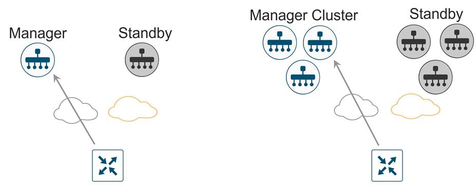
● The Manager can be deployed in two basic ways, either standalone or by clustering. All Manager instances inside a primary cluster operate in active mode. The purpose of a Manager cluster is scale. It does provide a level of redundancy against a single Manager failure, but it does not protect against a cluster-level failure. Clustering across geographical locations is not recommended, as database replication between cluster members requires 4 MS or less of delay between them. Therefore, members of a cluster should reside at the same site. Redundancy is achieved with a backup Manager or backup Manager cluster in standby mode.
● If you are running the Manager in standalone mode, deploy a Manager in active mode as primary, and a Manager in standby mode as backup. It is recommended to deploy these at two different geographical locations to achieve redundancy.
● If you are running the Manager in a cluster, deploy a Manager cluster in active mode as primary, and a Manager cluster in standby mode as backup. A cluster needs a minimum of three Manager instances, each being active and running independently. It is recommended to deploy each cluster at two different geographical locations to achieve redundancy.
The Validator and Controller are stateless. Snapshots of their virtual machines can be made before any maintenance or configuration changes, or their configurations can be copied and saved if running in CLI mode. In addition, if feature or CLI templates are configured on the Manager (required for the Controller if centralized policies are built and applied from the Manager), their configurations will be saved with the Manager snapshots and database. Snapshots can be restored, or the device can be re-deployed and configuration templates pushed from the Manager in a disaster recovery scenario.
The Manager is the only stateful SD-WAN control component, and its backup cannot be deployed in active mode. For the Manager server, snapshots should be taken, and the database backed up regularly.
There are different disaster recovery methods available. In common disaster recovery scenarios, an active Manager or Manager cluster resides at one data center site, along with at least one active Controller and Validator. In a second data center, a standby (inactive) Manager or Manager cluster is deployed, along with at least one active Controller and Validator. On the active Manager or Manager cluster, each Manager instance establishes control connections to Controllers and Validators in both data centers. When the standby Manager or Manager cluster becomes active, it then establishes control connections to the Controllers and Validators in both data centers.
The following disaster recovery methods are available:
● Manual (Manager standalone or cluster) – The backup Manager server or Manager cluster is kept shutdown in cold standby state. Regular backups of the active database are taken, and when the primary Manager or Manager cluster goes down, the standby Manager or Manager cluster is brought up manually and the backup database restored on it.
● Administrator-triggered failover (Manager cluster) (recommended) – In this method, the data is replicated automatically between the primary and secondary Manager clusters, but you must manually perform the Failover to the secondary cluster. This is supported starting in the 19.2 version of Manager code. This is the recommended disaster recovery method.
| Technical Tip |
| Note that administrator-triggered failover disaster recovery for a single node Manager deployment is supported starting in Manager version 20.5. This document only covers administrator-triggered failover for a Manager cluster deployment. |
Design: Administrator-Triggered Disaster Recovery Method
Starting in the 19.2 version of Manager code, the administrator-triggered disaster recovery failover option can be configured. This disaster recovery method applies to Manager clusters which are primary and backup to each other. Note that this method is supported for standalone primary and secondary Manager servers starting in Manager code version 20.5, but this document is focused only on cluster deployments.
For this method, a Manager cluster is configured at one datacenter, while a second Manager cluster is configured at a second datacenter. The two clusters communicate with each other over a DCI link between the datacenters and the clusters must communicate via their cluster link, which is part of VPN 0. Data is replicated automatically between the primary and secondary Manager clusters and a Failover to the secondary cluster is performed manually.
Other control components (Controllers and Validators) are deployed across both primary and secondary data centers and are reachable from Manager servers from both data centers through the transport interfaces. At any given time, however, these control components are connected only to the primary Manager cluster.
The following diagram depicts a typical admin-triggered disaster recovery topology. Note that the Manager cluster link for each Manager is extended across the datacenters and all Manager servers are reachable through this out-of-band interface. Control connections are established from each Manager to other Manager servers in the same cluster through the VPN 0 transport interface and to the Controllers and the Validators in either datacenter through the same interface.

Prerequisites, Best Practices and Recommendations
Some of the best practices and recommendations for Manager clustering and administrator-triggered failover deployment include -
● Deploy each Manager VM on a separate physical server within a datacenter so that a single physical server outage will not impact the Manager cluster for a given datacenter.
● All Manager servers should be running the same software version.
● For each Manager instance within a cluster, a third interface (cluster link) is required besides the interfaces used for VPN 0 (transport) and VPN 512 (management). This interface is used for communication and syncing between the Manager servers within the cluster. This interface should be at least 1 Gbps and have a latency of 4ms or less. A 10 Gbps interface is recommended.
● In ESXi, it is recommended to use VMXNET3 adapters for interfaces. VMXNET3 supports 10 Gbps speeds. To make VMXNET3 NICs available, under ESXi 5.0 and later (VM version 8) compatibility settings, under Edit Settings>VM Options>General Options, choose a Guest OS version that supports VMXNET3 (such as Ubuntu Linux (64-bit) or Red Hat Linux 5 (64-bit) or greater).
● Within a cluster, all Manager nodes should reside on the same LAN segment and be able to reach each other on the out-of-band interface (cluster link). Between datacenters, all Manager servers should also be able to reach each other through the out-of-band interface (cluster link), either through an extended layer 2 segment or through layer 3 routing.
● Across data centers, the following ports need to be enabled on the firewalls for the Manager clusters to communicate with each other:
◦ TCP ports: 8443, 830
● The current supported Manager cluster administrator-triggered failover topology requires all services (application-server, configuration, messaging server, coordination server, and statistics) to be enabled on all the Manager servers in the cluster.
● The configuration and statistics service should be run on at least three Manager devices. Each service must run on an odd number of devices because to ensure data consistency during write operations, there must be a quorum, or simple majority, of Manager devices running and in sync.
● Ensure that you use a net admin user privilege for Disaster Recovery (DR) registration. We recommend that you modify the factory-default password, admin before you start the registration process.
To change user credentials, we recommend that you use the Cisco Catalyst Manager GUI, and not use the CLI of the Cisco Catalyst SD-WAN device.
● If Cisco Catalyst SD-WAN Manager nodes are configured using feature templates, ensure that you create separate feature templates for both primary data center and secondary data center.
When primary cluster is switched over to the secondary cluster, Cisco Catalyst Manager detaches the Cisco Catalyst SD-WAN devices from the feature templates. Therefore, ensure that you reattach the devices to the specific feature templates.
● For an on-premises deployment, ensure that you regularly take backup of the Configuration database from the active Cisco Catalyst Manager instance.
Deployment: Manager Cluster Disaster Recovery (DR)
This section explains the prerequisites and steps to configure administrator triggered disaster recovery failover for a Manager primary/secondary cluster design. The primary and standby Manager clusters are configured with the same number of instances running the same services, and each cluster is in a separate data center.
The Manager cluster design followed in this guide helps achieve:
● Manager redundancy that provides high availability should one Manager in a cluster fail.
● Administrator-triggered failover Disaster Recovery (DR), providing redundancy for an entire cluster should the whole datacenter fail.
Prerequisites to enable Disaster Recovery:
1. Install and configure the required number of Manager instances in a virtual environment. Create a third interface on each Manager device within VPN 0. This is the out-of-band or cluster interface configured on VPN 0 of each Manager node involved in disaster recovery. This is the same interface that is used by the Manager for communicating with its peers in a cluster.
Note: You need at least three nodes in each of the two Manager clusters to enable DR. Therefore, install and deploy 6 Manager instances.
2. Within each Manager instance, the organization name must be configured, certificates installed, and tunnel interfaces active. The bare minimal configuration on each Manager instance is as given below,
system
host-name
system-ip
site-id
organization-name
vbond
vpn 0
interface (tunnel interface)
ip address
tunnel-interface
no shutdown
interface (out-of-band/ cluster interface)
ip address
no shutdown
ip route 0.0.0.0/0 (next hop for tunnel interface)
Make sure all Manager servers can reach each other’s out-of-band/ Cluster interface.
3. To install a Manager cluster, follow the steps listed in https://www.cisco.com/c/en/us/td/docs/routers/sdwan/configuration/sdwan-xe-gs-book/manage-cluster.html. Note, the current supported Manager cluster topology requires all services to be enabled on all the Manager servers in the cluster. This includes, application-server, configuration-db, messaging server, coordination server and statistics-db.
4. Before starting with the DR registration procedure, ensure that no other procedures are running such as software upgrades, template attachments etc. on either the primary or secondary cluster. Note, DR must be registered on the primary Cisco Catalyst Manager cluster.
Process 1: Disaster Recovery Registration
Step 1. Log into any Manager instance, that is a part of the primary cluster to begin the Disaster Recovery registration process.
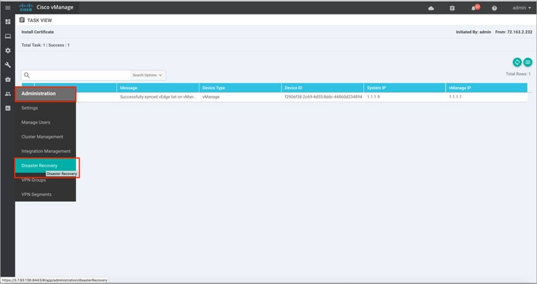
Step 2. Navigate to Administration > Disaster Recovery.
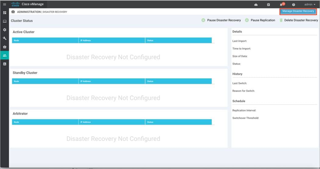
Step 3. Click on Manage Disaster Recovery to enter the out-of-band/ cluster IP address of a Manager instance from the primary cluster, along with the admin username and password for the cluster.
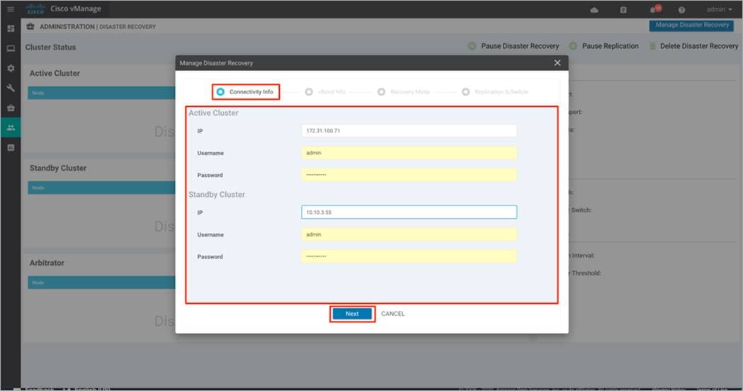
Step 4. Under Connectivity Info:
● Enter the out-of-band/ cluster IP address of one of the Manager instances in the active cluster and credentials for the active cluster.
● Then, enter the out-of-band/ cluster IP address of any of the Manager instances in the standby cluster, followed by the username and password for the standby cluster.
Finally, click Next to continue.
| Technical Tip |
| Once you have entered the password here and configured DR, do not change that password. |
Step 5. Under vBond Information, enter the IP address and the admin User Name and Password for the first Validator in the primary cluster.
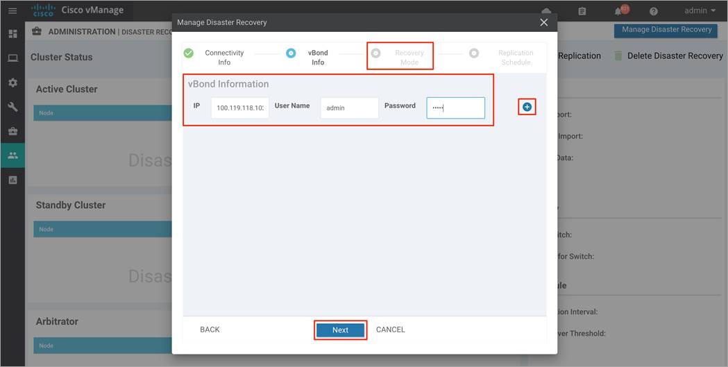
Note, if you have more than one Validator in the deployment, click on the + button to enter details to the second Validator. Repeat this step, until you have listed all the Validators in your deployment. Finally, click Next to continue.
| Technical Tip |
| Once you have entered the password within the vBond Information and configured DR, do not change that password. |
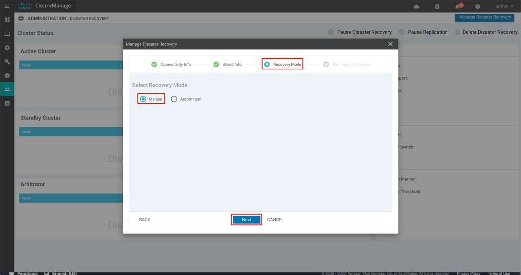
Step 6. In this deployment, the Recovery Mode is set to Manual.
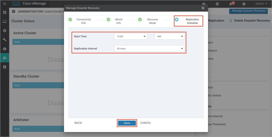
Step 7. Under the Replication Schedule, enter the Start Time and Replication Interval. In a production environment, the Replication Interval must be configured to at least 30 minutes. The control component and edge lists are uploaded to the standby cluster, during the first replication.
Finally, click Save.
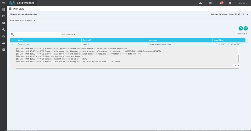
Step 8. You will be navigated to the Disaster Recovery Registration page. This will restart the Application Server on each of the Manager devices, including on the Manager where you are currently using the GUI. The registration may take up 20-30 minutes to complete. Refresh the browser to see that DR is successfully configured.
| Technical Tip |
| When the Application Server restarts on the Manager that you are using, an error may be displayed at the top of the page. This is normal because the browser is trying to refresh the page while the Application Server is restarting. |
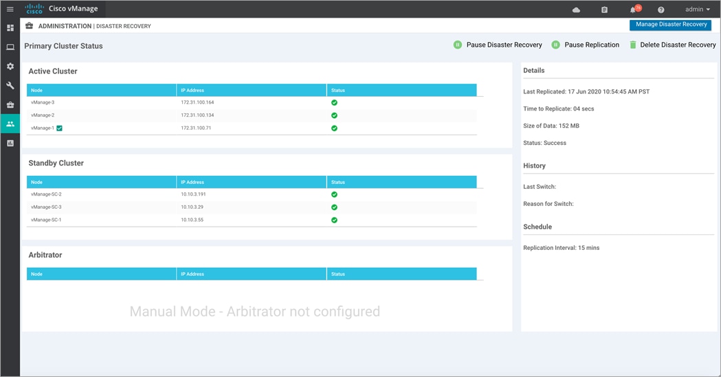
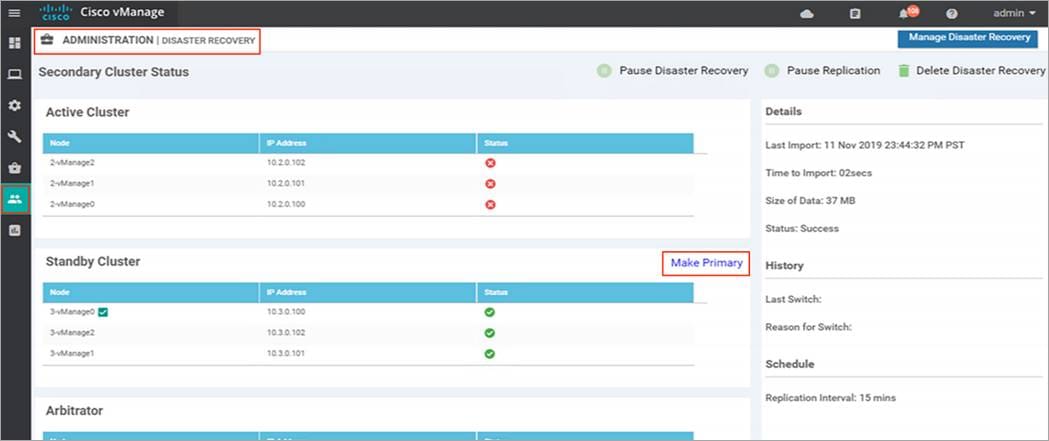
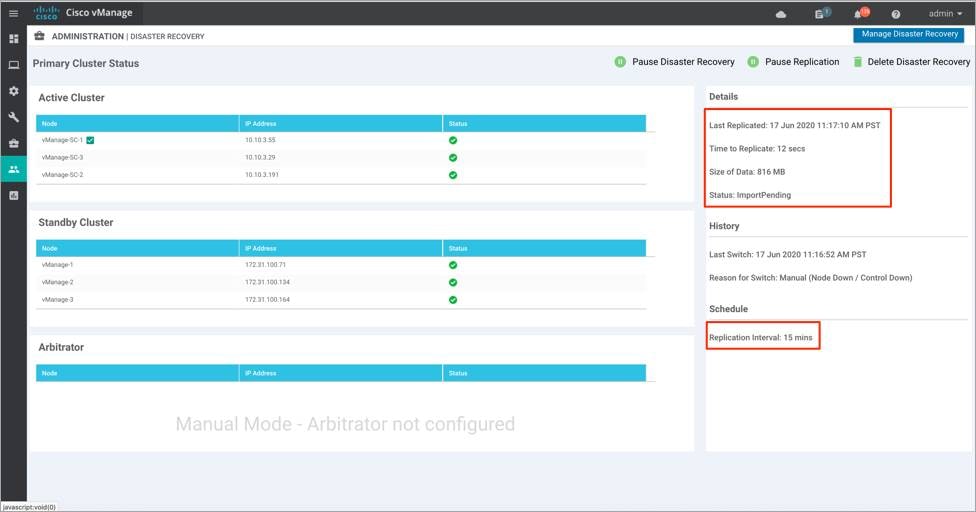
Step 9. Navigate back to the Administration > Disaster Recovery to view the status of the active and standby clusters.
The example figure below is taken from the primary Manager cluster, wherein the DR registration was initiated.
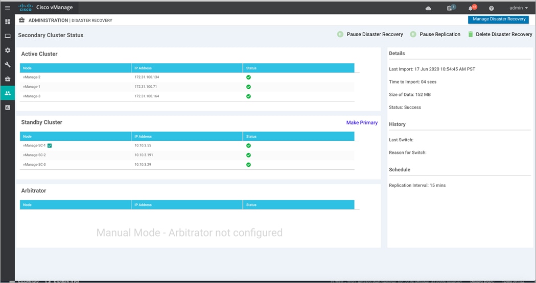
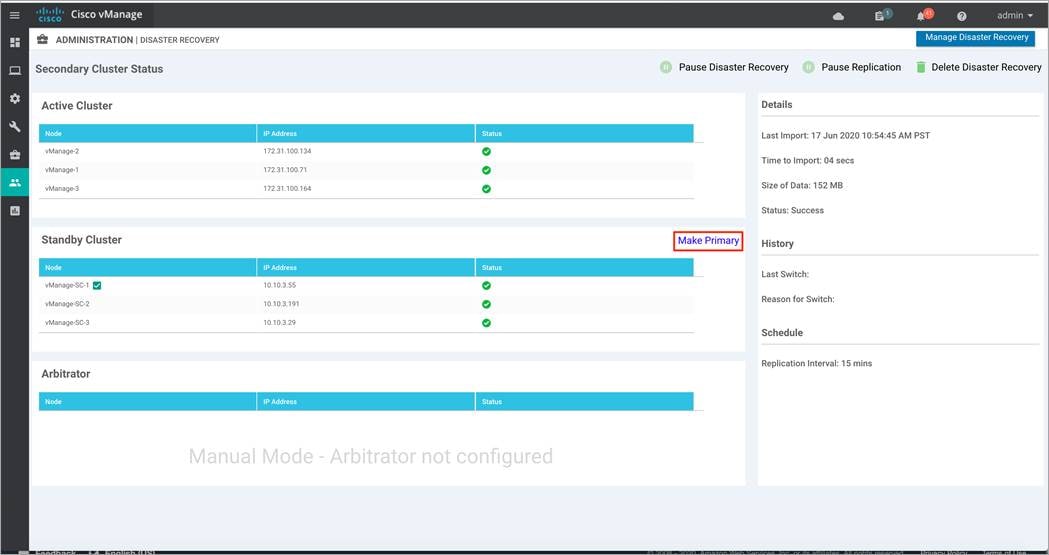
And the following figure displays the view from a secondary Manager cluster.
Process 2: Manual Failover
A manual scheduled failover helps test the operation of disaster recovery.
Overall steps to perform manual Failover include the following:
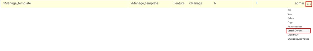
● Begin by detaching device templates associated with the Cisco Catalyst Manager nodes of the primary cluster before you perform a Failover. Note: Detach device templates attached to a Manager node.
● Shut off the tunnel interfaces part of the primary Cisco Catalyst Manager cluster to prevent devices from toggling during the Failover.
● From a Cisco Catalyst Manager system on the secondary cluster, wait for data replication to complete and then click Make Primary to enable the Failover.
Step 1. Navigate to Administration > Disaster Recovery on one of the standby cluster nodes. Within Standby Cluster, look for the option Make Primary located in the middle of the screen. Click this option, after the tunnel interfaces on the active Manager cluster is shut.
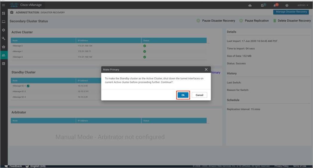
Step 2. A pop-up screen displays the following. Again, make sure to shut down tunnel interface on all nodes of the current active cluster before clicking Ok.
Step 3. The Failover process starts again.
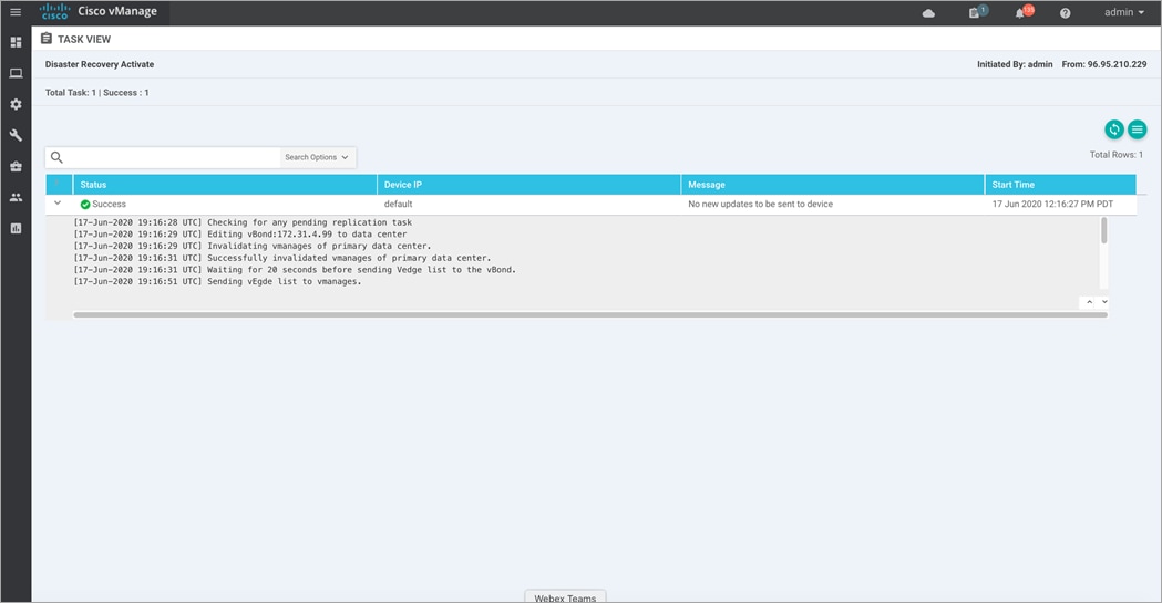
Step 4. Post successful completion of the Failover process, the Manager cluster that was previously in standby status will now be active.
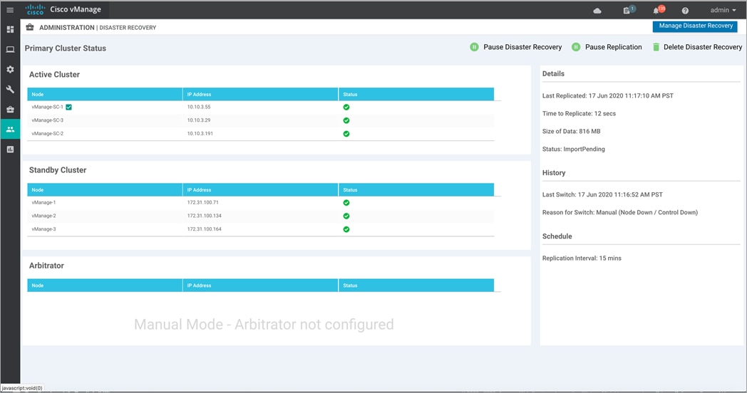
| Technical Tip |
| The green tick marks that indicate the status of each Manager instance is based on a simple ping test to the cluster out-of-band interface on each node, which takes up to a minute to recognize that the interface is unreachable. The status icon does not indicate the status of the tunnel interface itself. This means it is possible for the green check mark to still show green when the tunnel interfaces are down, and the cluster is impacted. Verify that the devices are offline and/or the tunnel interfaces are shut down before attempting a Failover. |
Step 5. Lastly, turn on the tunnel interfaces on all the nodes of the new Active cluster. This brings up the control connections from other control component(s)/ devices.
Devices and control components converge to the secondary cluster and that cluster assumes the role of the primary cluster. When this process completes, the original primary cluster assumes the role of the secondary cluster. Then data replicates from the new primary cluster to the new secondary cluster.
Process 3: Disaster Recovery Operations
This section describes how to handle a disaster recovery in a variety of situations.
Procedure 1. Failover due to Loss of Primary Manager Cluster
This procedure explains the steps followed to Failover from primary to secondary (standby) Manager cluster, due to loss of all the Manager(s) of the primary cluster.
| Technical Tip |
| Do not manually switch over unless all of the active cluster nodes show red and tunnel interfaces are shut down. If one or more of the active cluster nodes has control connections, the Failover may fail. |
Step 1. Log in to Manager GUI on the secondary cluster and select Administration > Disaster Recovery.
Step 2. Click Make Primary.
The devices as well as control components will converge to standby cluster, and it assumes the role of primary.
When the original primary Manager cluster is recovered and back online, it assumes the role of secondary cluster and starts receiving data from the primary cluster.
| Technical Tip |
| ● If a partial loss of the primary Cisco Catalyst Manager cluster is seen, we recommend that you try to recover the primary cluster instead of switching over to the secondary cluster. A cluster with N nodes is operational if (N/2) +1 nodes are operational. A cluster with N nodes becomes read only if (N/2) +1 or more nodes are lost. ● Also, note the operator needs to validate that the tunnel interface is shut on the original primary cluster once it is up or back online. This operation cannot be performed until the cluster is up. |
Procedure 2. Failover due to Loss of Primary Data Center
This procedure focuses on the steps followed to Failover from primary to secondary (standby) Data Center if the primary Data center cluster goes down.
Step 1. Log in to Manager GUI on the secondary cluster and select Administration > Disaster Recovery.
Step 2. Click Make Primary to begin the Failover process.
During the Failover, only the Cisco Validators in the secondary data center are updated with a new valid Cisco Catalyst Manager list. As a result, the edge devices and control components (which are online) converge to the stand by cluster and it assumes the role of the primary cluster.
After the original primary data center recovers and all VMs including control components, are back online, then these control components are updated with a new valid Cisco Catalyst Manager and converge to the new primary Cisco Catalyst Manager cluster. The original primary cluster assumes the role of secondary cluster and begins to receive data from the primary cluster.
| Technical Tip |
| ● The operator needs to validate that the tunnel interface is shut on the original primary cluster once it is up or back online. This operation cannot be performed until the site is up. ● Also note, In the event that a link failure occurs between your data centers but the WAN in the primary data center is operational and data replication fails. In such situations, attempt to recover the link so that data replication can resume. |
Operate: Administrator-Triggered Disaster Recovery Method
This section explains some of the common troubleshooting tips and errors noticed on enabling Disaster Recovery (DR).
Common Issues seen during registration:
Device Registration Fails
Solution: Verify the reachability to the Validator from all cluster members on the secondary cluster/reachability between the secondary cluster and primary cluster on the transport interface (VPN 0)/ Check that you have the correct username and password.
Failed to find vBond IP/UUID in the registration task details page
Solution: Make sure the Validators are both connected to the registered data center before retrying registration. If the error occurs while the Validators are already connected then, go to the rediscover page on the primary Manager(s) GUI and rediscover the Validators. This action will ensure that a corresponding entry of Validator/vBond is present in the configuration-db.
Timeout while clicking next on any registration step
Solution: Make sure IP address is reachable and credentials provided are correct.
Some Common Troubleshooting Tips:
● Verify the replication details status on the disaster recovery page to ensure all data is being transferred from primary Manager cluster to secondary cluster.
In case of replication failure: Verify IP reachability from primary Manager cluster.
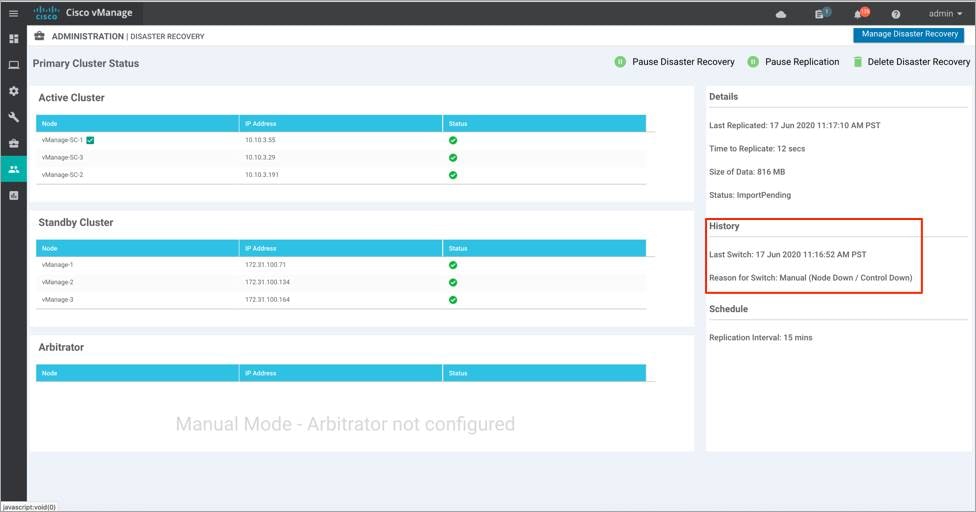
● Verify the Failover timestamp on primary and secondary clusters in situations of Failovers.
The following products and software versions are included as part of validation in this deployment guide. This validated set is not inclusive of all possibilities.
Table 1. Cisco Catalyst SD-WAN Hardware
| Product |
Software version |
| Manager |
20.1.1 |
| Validator |
20.1.1 |
| Controller |
20.1.1 |
For comments and suggestions about this guide and related guides, join the discussion on Cisco Community at https://cs.co/en-cvds.