Software-Defined Access Macro Segmentation Deployment Guide
Available Languages
Bias-Free Language
The documentation set for this product strives to use bias-free language. For the purposes of this documentation set, bias-free is defined as language that does not imply discrimination based on age, disability, gender, racial identity, ethnic identity, sexual orientation, socioeconomic status, and intersectionality. Exceptions may be present in the documentation due to language that is hardcoded in the user interfaces of the product software, language used based on RFP documentation, or language that is used by a referenced third-party product. Learn more about how Cisco is using Inclusive Language.
- US/Canada 800-553-2447
- Worldwide Support Phone Numbers
- All Tools
 Feedback
 Feedback
Cisco DNA Center (DNAC) is the network management and command center for Cisco DNA, built on intent-based networking principles, it helps you build the new network and deliver better experiences more securely, so you can focus on your business, and not on your network. It creates a holistic end to end platform for your enterprise so you can better manage the business and its not only Graphical Interface, but builds on 30 years of Cisco Networking known how’s. Cisco DNA Center provides a centralized management dashboard for complete control of this new network. This platform can simplify IT network operations, proactively manage the network, provide consistent wired and wireless policy, and correlate insights with contextual cognitive analytics.
Cisco DNA Center is a dedicated hardware appliance powered through a software collection of applications, processes, services, packages, and tools, and it is the centerpiece for Cisco® Digital Network Architecture (Cisco DNA™). This software provides full automation capabilities to deploy networks in minutes, perform device upgrades and patches networkwide with a single click and help ensure configuration consistency and save your team time. It also provides visibility and network assurance through intelligent analytics combined with AI/ML which has more than 30 years of best practices to help optimize your network's performance, reduce troubleshooting time for your team, and lower the cost of network operations
Cisco Software-Defined Access (SD-Access) is the industry’s first intent-based networking solution for the Enterprise built on the principles of Cisco’s Digital Network Architecture (Cisco DNA). Cisco SD-Access provides automated end-to-end segmentation to separate user, device and application traffic without redesigning the network. Cisco SD-Access automates user access policy so organizations can make sure the right policies are established for any user or device with any application across the network. This is accomplished with a single network fabric across LAN and WLAN which creates a consistent user experience anywhere without compromising on security.
Building this next-generation solution involved some key foundational element including:
Controller-based orchestrator to drive business intent into the orchestration and operation of network elements including day-0 configuration of devices and polices associated with users, devices and endpoints as they connect to network.
Network fabric leveraging Virtual Network (VN) overlays in order to support mobility, segmentation and programmability at very large scale.
Programmable switches to build a modern infrastructure for automated device provisioning, open API interfaces, granular visibility using telemetry capabilities along with seamless software upgrades.
This guide is intended to provide technical guidance to design, deploy and operate Macro Segmentation across Software-Defined Access Fabric. It focuses on the steps to enable device level Segmentation across the SD-Access Fabric and Fusion device configuration to handle communication between separate VN’s or VRF or from VN/VRF to Shared services residing at the Data Center.
This guide contains four major sections:
The Define section defines problem being solved with Macro Segmentation and provides information about how to plan for deployment, and other considerations.
The Design section highlights the typical deployment topology and discusses Border and Fusion device considerations.
The Deploy section provides information about various procedures to deploy the solution along with recommended practices.
The Operate section shows how to verify segmentation is in place and endpoints in one VN or VRF is not allowed to communicate with endpoints in other VN by default, unless permitted.
What is covered in this Guide?
This guide provides guidance to Cisco Software Defined Access customers who want to segment and protect their wired or wireless networks designed with Cisco Catalyst Switch platforms. The configurations listed in this document are working configurations that have been validated on a Cisco Catalyst 9000 series switches, Cisco Wireless Lan Controllers, Cisco DNA Center & Cisco ISE. The code versions are listed in Appendix A for your convenience
There are two options to integrate wireless into an existing wired network which is based on Cisco SD Access. CUWN Wireless Over the Top (OTT) which is the existing CAPWAP tunnel (both Data and Control Plane) extending between the APs to WLC and Fabric Enabled Wireless (FEW) where control plane is centralized and data plane is distributed using VXLAN directly from the Fabric enabled AP’s. The focus in this document is on Fabric Enabled Wireless as OTT wireless does not provide all the benefits of the Fabric integrated SD-Access wireless deployment. A truly integrated SD-Access wireless deployment provides support for integrated two-level segmentation, greater scalability via the use of a distributed data plane and consistent policy for both wired and wireless users.
What is not covered in this Guide?
Although this prescriptive deployment guide is about Cisco DNA Center and Software Defined Access, it does not cover the installation of the Cisco DNAC appliance, validating Micro segmentation uses cases, connecting multiple sites using SD-Access or SD-WAN transit, Extended Nodes and Fabric-in-a-box architecture.
Prior knowledge of LISP, VXLAN and ISE fundamentals are not required but may be helpful in understanding certain SDA functionality and SDA components.
This section provides a high-level overview of Software-Defined Access solution and components
SD-Access Deployment Components
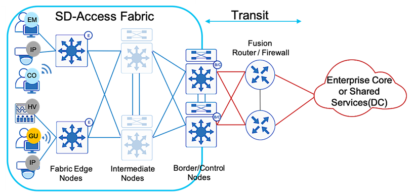
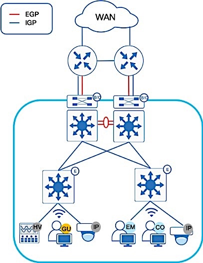
The SD-Access 1.3 solution in Figure 1 supports provisioning of the following fabric components
Fabric edge node (E): Equivalent to an access layer switch in a traditional campus LAN design which provides first-hop services for Endpoints, IP phones, and access points directly connected to a fabric.
Fabric control plane node (C): One or more network elements that implement the LISP Map-Server (MS) and Map-Resolver (MR) functionality. The control plane node’s host tracking database keep track of all endpoints in a fabric site and associates the endpoints to fabric nodes in what is known as an EID-to-RLOC binding in LISP.
Fabric border node (B): One or more network elements that connect the SD-Access fabric to the networks external to the Fabric and serves as the Entry & Exit point for data traffic. The border node is the device physically connected to a transit or to a next-hop device connected to the outside world.
Fabric site: An independent fabric that includes a control plane node and edge node and usually includes an ISE Policy Service Node (PSN) and fabric-mode WLC. A fabric border node is required to allow traffic to egress and ingress the fabric site.
Fabric WLC: With SD-Access Wireless, the Control plane is centralized. This means that, as with CUWN, a CAPWAP tunnel is maintained between APs and WLC. the main difference is that, the data plane is distributed using VXLAN directly from the Fabric enabled APs.
Virtual Network (VN): Equivalent to virtual routing and forwarding (VRF) instances in traditional segmentation environment. VNs are created in the Policy application and provisioned to the fabric nodes as a VRF instance. VN and VRF are used interchangeably in this document.
Scalable Group Tag (SGT): A Cisco TrustSec component that operates as a form of metadata to provide logical segmentation based on group membership.
Transit: Connects a fabric site to an external network (IP-Based transit) or to one or more fabric sites (SD-Access transit). IP-Based transit networks connect the fabric to external networks using VRF-lite. SD-Access transits carry SGT and VN information inherently carrying SGTs and maintaining segmentation between fabric sites without requiring VRF-lite.
Fabric domain: Encompasses one or more fabric sites and any corresponding transit(s) associated with those sites.
Host Pool: The binding of a reserved IP address pool to a Virtual Network which associates a segment to a VRF.
In all network deployments there is a common set of resources needed by every endpoint. The following are some common examples:
● Identity services (e.g. AAA/RADIUS)
● Domain name services (DNS)
● Dynamic host configuration protocol (DHCP)
● IP address management (IPAM)
● Monitoring tools (e.g. SNMP)
● Data collectors (e.g. NetFlow, syslog)
● Other infrastructure elements
These common resources are often called “Shared services”. These shared services will generally reside outside of the SD-Access fabric. In most cases, such services reside in the Datacenter and are part of the Global Routing Table (GRT).
SD-Access fabric clients operate in overlay virtual networks. Thus, if the shared services are part of the global routing space or part of another VRF, some method of VRF route leaking between user VRFs and Shared services is required, and this is achieved using a Fusion device or Firewall.
In the Software Defined Access solution, devices are managed and configured by Cisco DNAC, but there is a part of the topology known as the underlay which has to be manually configured via CLI. A Fusion device is basically an external Router, L3 Switch, or Firewall which is located outside of the SD-Access Fabric and performs basic inter-VRF route leaking (import/export of routes from one VN to another VN) in order to allow communications between VRFs or between one VN/VRF and the Global routing table (GRT).It doesn’t have to be a dedicated device performing route leaking, rather any upstream device (WAN/MAN device or even Data Center L3 Switch) connected to the border node can perform this functionality if it supports advanced routing capabilities. This guide depicts the fusion device directly connected to the border node and location elsewhere is beyond the scope of this document.
Segmentation is a method used to separate specific group of users or devices from other group(s) for security purposes. SD-Access network segmentation can be described as a process of breaking down or splitting a single large network with a single routing table into any number of smaller logical networks (segments) providing isolation between segments, minimizing attack surface and introducing enforcement points between segments. Segmentation within SD-Access takes place at both a MACRO and MICRO level through virtual networks and SGTs respectively. By providing two levels of segmentation, SD-Access makes a secure network deployment possible for enterprises, and at the same time provides the simplest such approach for organizations to understand, design, implement and support. In the SD-Access Fabric, information identifying the virtual network and scalable group tag (SGT) are carried in the VXLAN network identifier (VNI) field with the VXLAN-GPO header.
In SD-Access, some enhancements to the original VXLAN specifications have been added, most notably the use of scalable group tags (SGTs). This new VXLAN format is currently an IETF draft known as Group Policy Option (or VXLAN-GPO).
Macro Segmentation logically separates a network topology into smaller virtual networks, using a unique network identifier and separate forwarding tables. This is instantiated as Virtual Routing and Forwarding (VRF) instance on switches or routers and referred to as a Virtual network (VN) on Cisco DNA Center.
A Virtual network (VN) is a logical network instance within the SD-Access fabric, providing layer 2 or Layer 3 services and defining a Layer 3 routing domain. As described above, within the SD-Access fabric, information identifying the virtual network is carried in the VXLAN Network Identifier (VNI) field within the VXLAN header. The VXLAN VNI is used to provide both the Layer 2(L2 VNI) and Layer 3(L3 VNI) segmentation.
Within the SD-Access fabric, LISP is used to provide control plane forwarding information. LISP instance ID provides a means of maintaining unique address spaces in the control plane and this is the capability in LISP that supports virtualization. External to the SD-Access fabric, at the SD-Access border, the virtual networks map directly to VRF instances, which may be extended beyond the fabric. The table below provides the terminology mapping across all three technologies
| Cisco DNA Center |
Switch/Router side |
LISP |
| Virtual Network (VN) |
VRF |
Instance ID |
| IP Pool |
Vlan/SVI |
EID Space |
| Underlay Network |
Global Routing Table |
Global Routing Table |
Each network is unique, and each environment has its own challenges. This section provides an overview of the topology as seen in Figure 2, used throughout this guide and describes important design considerations.
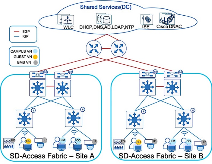
The Shared Services block contains the Cisco DNA Center hardware appliance which serves as a key component for implementation of automation and assurance capabilities in the Cisco SD-Access solution. Deployments may consist of one physical (single-node) appliance and can be expanded into a three-node cluster for high availability (HA). Cisco DNA Center provides the platform from which an SD-Access solution is designed, provisioned, monitored, and maintained.
The Cisco DNA Center software also integrates Cisco ISE nodes configured and dedicated to achieve policy and segmentation capabilities of SD-Access like Authentication, Authorization and Accounting (AAA) for secured fabric access. Cisco ISE provides a key security platform for integration of user/device identity into the SD-Access network and allows for policy and segmentation capabilities to be defined using endpoint and group identity rather than traditional IP addressing.
The SD-Access solution encompasses both Wired and Wireless network elements to provide the ability to create a seamless network fabric and implement consistent management and policy across Wired and Wireless infrastructure. As discussed previously, Wireless in SD-Access deployment is distributed at the edge switches for optimal performance and scalability and has centralized wireless control plane for RRM, client onboarding and client mobility. To support Cisco SD-Access Wireless, the solution includes both Cisco 9800 IOS XE based WLCs with controller redundancy at Site-A and AireOS controller at Site-B.
Within sites, in general, we recommend building hierarchical network designs similar to enterprise networks in order to provide scalability and redundancy at every network tier. While the three-tier architecture is proven in larger-scale enterprise campus networks, network design may vary based on the overall network size, physical connections and so on. The underlay topology represented in Figure 2 above shows two sites with collapsed core design (for simplicity and lower scale) connected by Enterprise WAN/IP Transit. The existing Enterprise core network runs Open Shortest Path First (OSPF) as the IGP routing protocol. This provides IP reachability between sites and shared services.
At each Fabric site, the underlay provides the basic transport for the network. Into the underlay are mapped all the physical network devices, such as Routers and Switches. The connectivity between these devices is provided using a fully routed network design with traditional Layer 3 routing protocol for a simple, stable and solid foundation that assists in providing the maximum uptime. The Core switches in each site operate as Fabric Border and Control Plane nodes which are the entry and exit point for the Fabric Site. Cisco DNA Center provides a prescriptive LAN automation service to automatically discover, provision and deploy network devices according to Cisco validated design best practices using the routed access deployment model and Intermediate System to Intermediate System (IS-IS) as the routing protocol. The network underlay is not used for client traffic; client traffic uses the Fabric overlay where all of the users, devices and things within a fabric-based network are mapped into. The overlay supports virtualized services such as segmentation for endpoints and supports constant changes as new services are added and deleted.
An SD-Access fabric domain may be composed of single or multiple sites. Each site may require different aspects of scale, resiliency, and survivability. Multiple fabric sites corresponding to a single fabric domain will be interconnected by a transit network. In general, a transit network area exists to connect to the external world and there are several approaches for external connectivity such as IP Transit, SD-Access Transit & SD-WAN Transit.
To provide end-to-end policy and segmentation, the transit network should be capable of carrying the endpoint context information (VRF and SGT) across the network. By default, Endpoint context information is not carried across the IP Transit network. Additional configuration like VRF-Lite across dot1q trunk or Sub-interface + SGT inline tagging are required to carry endpoint context information across an IP transit network. Border Gateway Protocol (BGP) is the protocol of choice between Fabric Border and Fusion/WAN device for route exchange since it provides an inherent way of preventing routing loops compared to any other IGP protocol. Routes from the existing enterprise network are mutually redistributed between BGP and the IGP(OSPF) and route-maps are used to prevent routing loops due to two-way redistribution.
In contrast, SD-Access Transit provides Campus/LAN like connectivity between fabric sites and maintains endpoint context or end to end segmentation across sites. With this transit type configurations are automated and complex mappings simplified with no requirement of Security Group Tag Exchange Protocol (SXP) to provide IP to SGT bindings. For more information on SD-Access Transit, please refer to SD-Access Transit for Distributed Campus Prescriptive Deployment Guide.
In the Define section, we have gone through the various segmentation technologies offered within SD-Access. This guide focuses mainly on Macro segmentation, hence let’s look at the business requirements driving the need for Macro segmentation.
Virtual networks (VNs) provide a first level of segmentation to ensure no communications between users and devices located in different Virtual Networks providing a macro level of segmentation as they separate blocks of users and devices. This is applicable to most organizations that host different types of users and things sharing a common network infrastructure and requiring isolation from one another while still having access to common set of shared network services.
When evaluating whether or not a specific business function or application warrants its own virtual network, it is important to assess the following criteria:
● Does the application or business function as well as the devices accessing it extend from the edge of the network into the core?
● Are the user and device communications primarily limited to that virtual network, with only limited access required in or out of the virtual network?
● Within a virtual network, will communications between devices be allowed?
● Will the scope of a network audit for regulatory compliance be reduced with the isolation enabled by a virtual network or VRF?
● Is there a requirement to completely isolate one type of users from another (e.g. Guest Users vs Corporate Users or Corporate user’s vs Building management system)?
Generally, if the answers to some of the above is yes, this may sway the decision to define a virtual network or VRF for these applications and functions. It is apparent that the use of virtual networks reduces the complexity of enforcing a security policy by strategically limiting access to only those that need it. Refer to SDA Segmentation Design Guide for more in depth information.
Below are some of the guidelines to consider on the number of virtual networks that need to be defined as these are fabric wide constructs.
● VRF-enabled device shares device resources (such as CPU, memory, hardware and so on) between various virtual instances. This essentially means splitting up of existing resources to number of Virtual networks defined.
● Use of VN does not eliminate the need for edge security functions. Therefore, many of the security features that are recommended at the edge of network should still be implemented and this is true of identity-based techniques such as 802.1x and MAB.
● VN is currently a “global” construct in SD-Access. This means that the fabric-enabled device with the lowest number of supported VRF entries (per-domain) will determine the per-domain scale limit. Select devices with sufficient VRF scale to support your fabric.
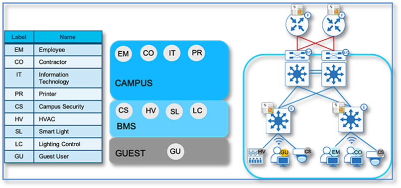
Hence the best approach for creating dedicated virtual networks is to start small and grow into it. As part of this deployment guide, since strict isolation is required between users and more vulnerable Building Management Systems (BMS) like HVAC, Campus Security, etc. All enterprise users are part of CAMPUS Virtual networks and Building Management systems in BMS Virtual Network. These are the some of the common virtual network definitions which appear in most enterprise networks.
Also, when considering Wireless Guest Design, SD-Access Fabric offers a dedicated Guest virtual network as another virtual network in the SD-Access Fabric where Guest Traffic can be extended to a DMZ via traditional methods from the Border node. This type of deployment eliminates the guest anchor controller and VN creation is fully automated by Cisco DNA Center providing a consistent solution and policy for Wired and Wireless guest users.
Also, when considering the number of virtual networks that need to be defined, another important consideration is whether or not communications between virtual networks is a requirement. If so, some form of inter VRF route leaking will be required which allows the advertisement or “leaking” of routes from one VRF to another. This requires a Fusion device supporting the BGP extended community attribute and route target import export functions. Although route target provides the mechanism to identity which VNs should receive the routes, it does not provide a facility that can prevent routing loops. These loops could occur if routes learned from a VN are advertised back to the same VN.
However, as useful as VNs are, they become even more powerful when augmented with micro-segmentation, which allows for a group-based access control even within a VN. Although this is out of scope in this document, additional information about micro-segmentation can be found in the SDA Segmentation Design Guide.
SD-Access Fabric Border Design Consideration
The fabric overlay works by tunneling traffic between routing locators (RLOC) which are always the Loopback 0 interface of the Fabric devices. Any traffic with a destination outside of the fabric site must traverse the border nodes.
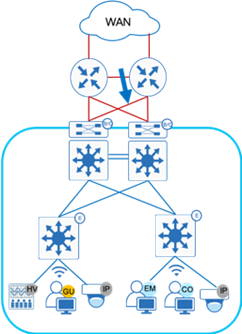
In the network topology depicted in Figure 3, where there isn’t a full mesh connectivity between Border Nodes and Fusion devices and the uplink interface or upstream device fails, the Loopback 0 interface (the RLOC) of that border node is still reachable by other Fabric devices in the fabric. This leads to a potential blackholing of packets. There is no built-in method in Cisco DNA Center provisioning or in LISP to mitigate this issue. To protect against such connectivity failures or an upstream device failure and to enable automatic traffic redirection, creating an iBGP neighbor relationship between the two border nodes for every configured VN and GRT is recommended.
Border nodes may be either Layer-3 switches which supports multiple logical connections using 802.1Q tagging on trunk interface or a true routing platform with sub interfaces on routers. This prescriptive deployment guide uses Catalyst 9500 High Performance switches as the fabric border nodes, therefore iBGP configuration will be shown using 802.1Q tagging using trunk interfaces and allowing selective VLANs on these trunks.
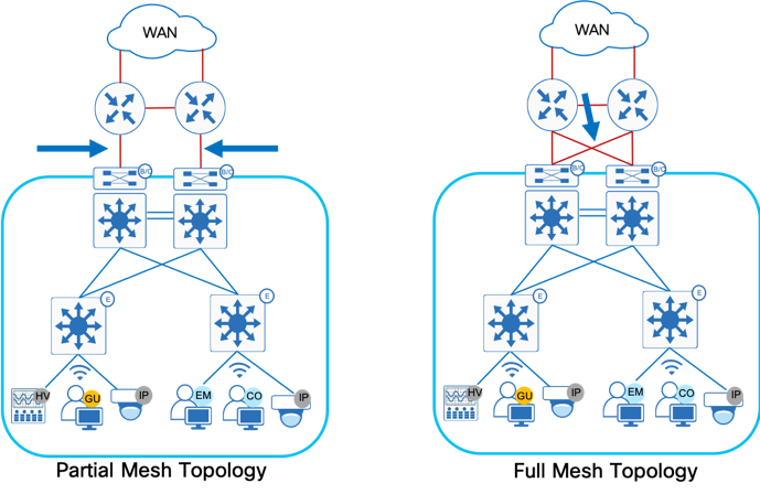
The preferred design uses a cross-link between redundant border devices, see Full Mesh Topology on Figure 3. In case of full mesh connectivity between Border nodes and Fusion devices as shown in Figure 3, iBGP neighbor relationship is not a mandatory requirement.
SD-Access Fabric Border Automation for External connectivity
The primary goal of Cisco DNA Center is to provide end to end automation to transform the network administrator’s business intent into device-specific network configuration. Naturally, there will always be traffic which needs to flow between the SD-Access Fabric endpoints and endpoints or servers located outside the fabric, in external networks. These traffic flows will take place via the Fabric Border nodes. Cisco DNA Center provides a prescriptive Layer 3 Border Handoff automation to automatically share same physical link carrying multiple VLANs between the Border Node and Fusion device. To connect border node devices into your enterprise network, you establish connectivity across interfaces configured using VRF-lite, which uses 802.1Q VLAN tagging to separate the VRFs in case of Layer 3 Switch or physical port configured with Sub-interfaces if using a Cisco Router.
As part of the Layer-3 border handoff automation, Cisco DNA Center will use Variable Length Subnet Mask (VLSM) on the defined Border Handoff automation pool to create multiple /30 subnets. Each subnet (equal to number of VN’s created) is associated with a VLAN ID and does support the reuse of VLANs when a device is provisioned and un-provisioned. Starting with DNAC release 1.3.3.x release, Cisco DNA Center User Interface border automation supports user defined VLAN ID to be used per VN for VRF-Lite handoff between border and fusion device. If left to default, Cisco DNA Center will provision the VLANs starting with 3001 and increments up to VLAN 3500 depending on number of virtual networks. If the border automation VLAN ID provisioned by Cisco DNAC is conflicting with VLAN ID used in your environment, you can manually configure VRF-Lite between the border node and the fusion device.
The external device handling routing among multiple virtual networks and a global routing instance acts as a fusion device for those networks. The separation of connectivity/routing tables is maintained using VRFs connected by 802.1Q-tagged interfaces to the border, also known as VRF-lite. Establishing the underlay connectivity using BGP allows Cisco DNA Center to manage initial discovery and configuration using the link, and then to use the same link augmented with additional tags and BGP sessions as needed for overlay VN connectivity. The underlay always resides in the global routing table.
SD-Access Fabric Border Connectivity between Border and Fusion device (Dual Links for Automation)
The following consideration is only applicable if there is not full mesh connectivity between border nodes and fusion devices .
For DNA Center to discover devices or to run LAN automation across the site, basic end to end underlay reachability to all fabric devices is required. If it is an existing infrastructure (brownfield) the connectivity (underlay) between these devices is provided using a fully routed network (IGP) design. If it’s a new infrastructure(greenfield), DNA Center LAN Automation can be used to fully automate the underlay connectivity using ISIS routed network Design.
Special consideration is required if only a single link exists between the border and fusion devices. As part of the border automation workflow, Cisco DNA Center automatically configures the links between border and fusion device with VRF-Lite and an external BGP handoff per VRF Instance. For this to succeed, the interface on the border connecting to the fusion device must not have any configuration, even a description. Hence, to ease the border automation and maintain DNA Center reachability to fabric devices, it is recommended to have dual links between the border and the upstream fusion device as seen by the red and blue line in Figure 4. This is so that reachability between Cisco DNA Center and the Fabric device is maintained by the IGP link (Blue Link) until the BGP relationship is fully established (GRT + Per VRF Instance) and redistribution between IGP and BGP is completed. Upon completing the border migration and establishing eBGP neighborship, eBGP routes will be preferred over IGP routes and hence it would then be safe to shut down and decommission the IGP/Blue link.
Several fusion device design considerations apply and are dependent on whether the shared services are located in the GRT or located in another VRF.
Shared services in the GRT
● The fabric border node forms an external BGP routing adjacency with the fusion device, using the global routing table
● On the border node, the same routing adjacency is formed in each VRF context (BGP address- family)
● On the fusion router, routes between the SD-Access VNs are exchanged with the GRT of the external network through selective route imports/export. Refer to Process 9 Procedure 5 for examples.
| Tech tip |
| BGP is the routing protocol of choice for this route exchange since it provides an inherent way of preventing routing loops (using AS_ PATH attribute). Other routing protocols can be used, but require complex distribute-lists and prefix- lists to prevent loops |
Shared services in separate VRF:
Similar to above method:
● The fabric border node forms an external BGP routing adjacency with the fusion router, using the global routing table.
● A separate routing adjacency is formed for each BGP address family, between the border node and fusion router.
● On the Fusion router, routes between the SD-Access VNs and Shared Services VN is leaked using Inter-VRF Route leaking concepts.
There are four main challenges using the fusion router method to achieve inter-VN communication:
● Multiple touch points: manual configuration must be done at multiple points (wherever the route-leaking is implemented)
● Route duplication: Routes leaked from one VRF to another are also programmed in the hardware tables for both VRFs, resulting in greater TCAM utilization
● Loss of SGT context: SGT group tags are not maintained across VRFs and must be re-classified once the traffic enters the other VRF if inline tagging is not manually configured on the links between the border and fusion devices.
● Traffic hair pinning: Inter-VN traffic needs to be routed to the fusion router, and then back to the fabric border node
This section focuses on deployment guidelines with various workflows starting from device discovery through to Fabric automation.
The steps defined in the following Processes are documented in the Cisco SD-Access Distributed Campus Prescriptive Deployment Guide. Please refer to that guide to complete the following procedures.
Cisco SD-Access Distributed Campus Prescriptive Deployment Guide
Process 1: Preparing the Network for Discovery
The topology in this prescriptive guide will leverage manual underlay configuration for the majority of the underlay network except access switches in both Site A and Site B. Lan Automation will be leveraged for Access Switches only to showcase the Automation capabilities available within the Cisco DNA Center.
Procedure 1. Steps for building manual underlay. For detailed configuration refer to the Appendix 4 section.
Step 1. Configure Underlay network devices management (Hostname, VTY, SNMP, Loopback and System MTU 9100) using the Cisco IOS XE CLI.
Step 2. Configure underlay network links for routed access connectivity.
Step 3. Enable routing connectivity (OSPF) at border towards external router (Fusion device).
Cisco SD-Access Distributed Campus Prescriptive Deployment Guide
Process 2: Discovering the Network Infrastructure
Step 1. Please refer to the Discovering the Network Infrastructure procedure to perform device discovery.
Step 2. Please refer to the Define the Network Device Role procedure to set the network device role.
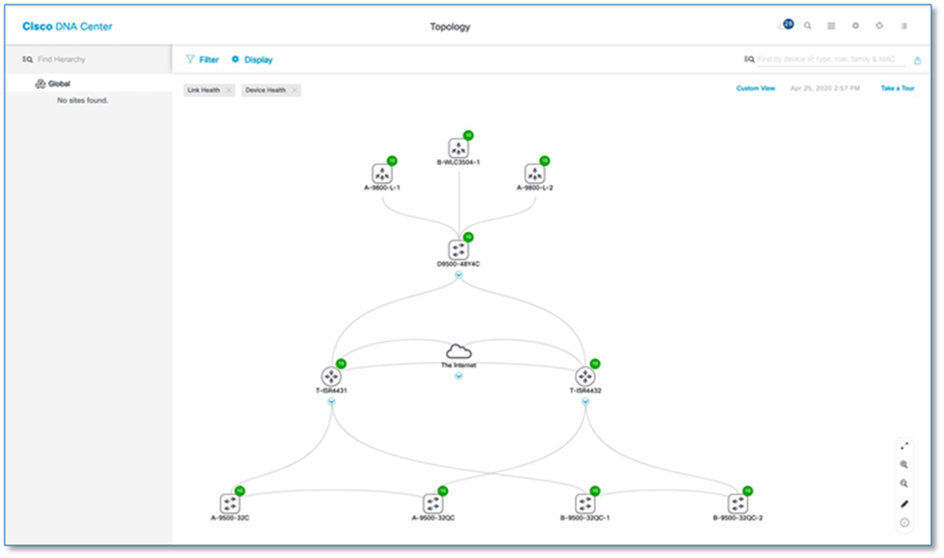
Step 3. Upon device discovery, navigate to Tools > Topology and select Toggle Topology View from the Cisco DNA Center Home page to view the network topology after Device Discovery.
Cisco SD-Access Distributed Campus Prescriptive Deployment Guide
Process 3: Integrating Cisco DNA Center with Identity Service Engine
Step 1. Please refer to the Integrating Cisco DNA Center with the Identity Services Engine process for integrating Cisco DNA Center with the Identity Services Engine in the Cisco SD-Access Distributed Campus PDG.
Cisco SD-Access Distributed Campus Prescriptive Deployment Guide
Process 4: Modeling Network using the Design Application
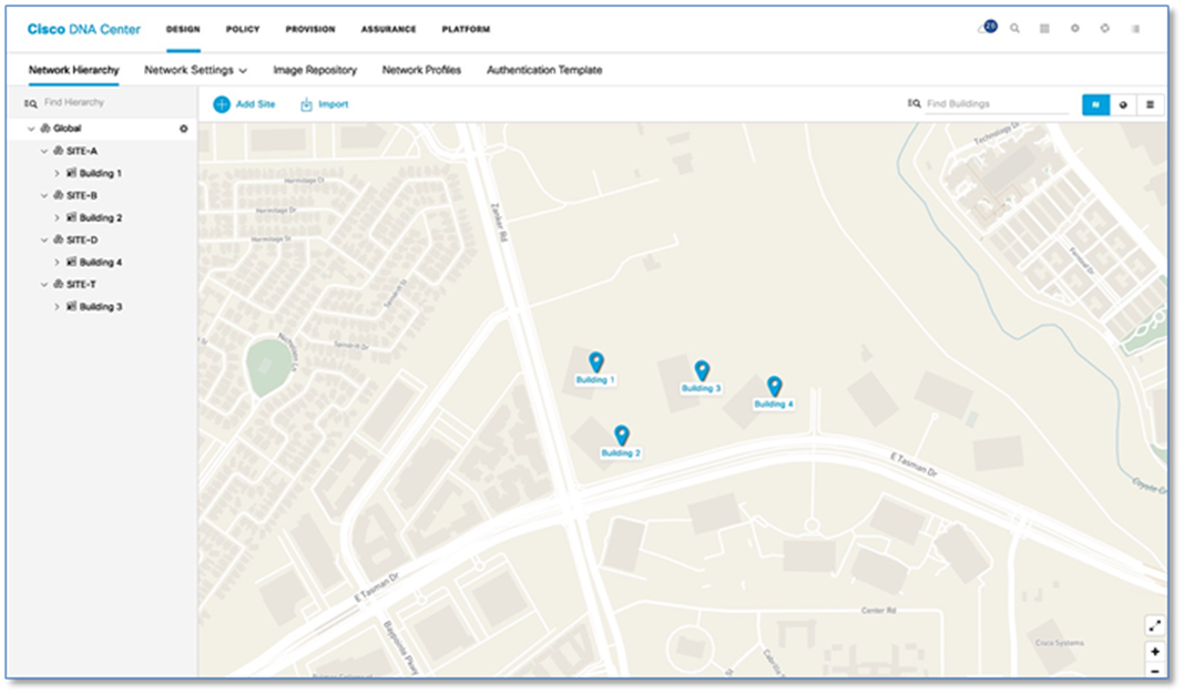
Procedure 1. Creating the network hierarchy
Step 1. Please refer to the Create the Network Hierarchy procedure in the Cisco SD-Access Distributed Campus PDG. Refer to Figure 6 below for Network Hierarchy created as per the topology in Figure 2.
Cisco SD-Access Distributed Campus Prescriptive Deployment Guide
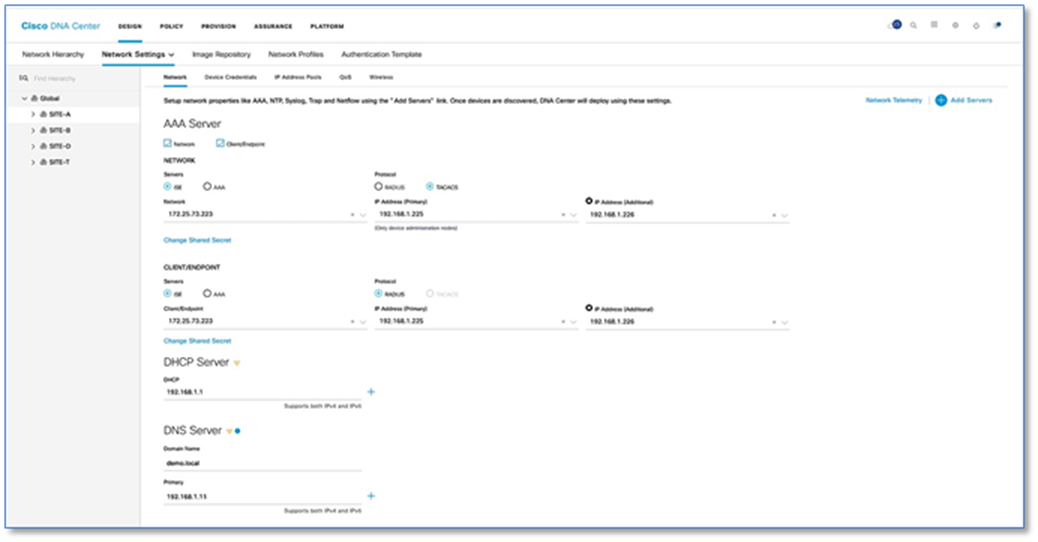
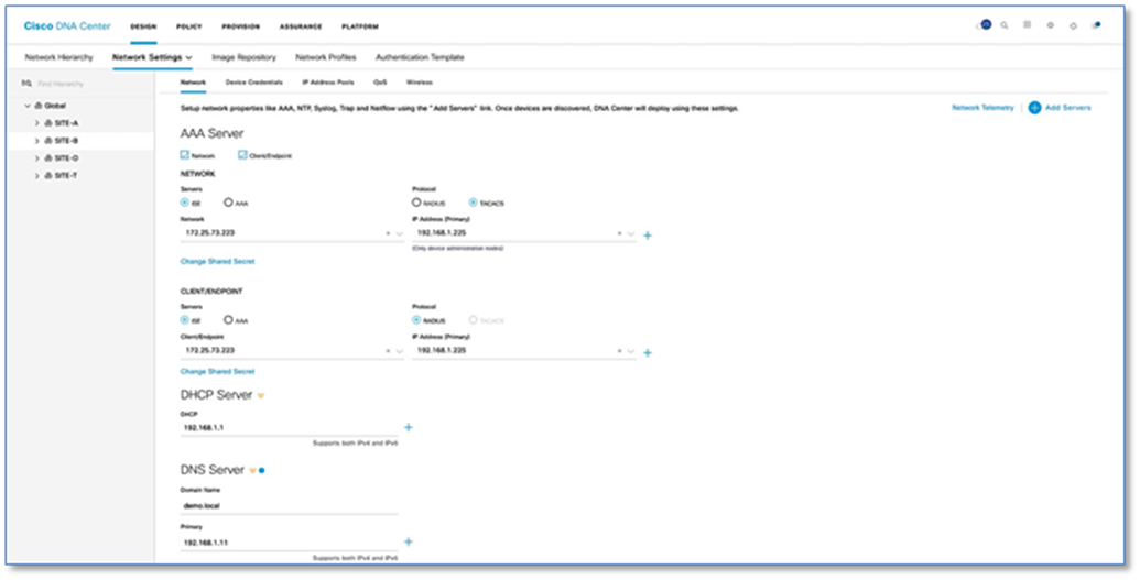
Procedure 2. Define network settings and services
Step 1. Please refer to the Define Network Settings and Services procedure in the Cisco SD-Access Distributed Campus PDG. Refer to the Figure 7 and 8 for defined Network Settings and Services for SITE-A (Figure 7) and SITE-B (Figure 8).
Cisco SD-Access Distributed Campus Prescriptive Deployment Guide
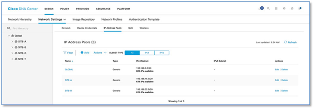
Procedure 3. Create and reserve IP address pool
IP address pools are created within Cisco DNA Center and are the IP subnets which are deployed for use by users, devices and things attached to the SD-Access Fabric. Host pools defined within a fabric deployment are bound to a given Virtual Network and rolled out to all Fabric edge switches in the fabric site. Each IP host pool is associated with a distributed anycast default gateway where every edge switch serves as a local default gateway for all endpoints connected to that switch.
Table 1 below shows an example of the Global IP address pools(/20s) which are created first at Global Level and reserved at site level(/24s) later.
Table 1. IP Address Pools Site-A and Site-B
| Location |
Pool Name |
Network/Mask |
Gateway |
DHCP Server |
DNS Server |
| Global |
192.168.0.0 |
192.168.0.0/20 |
- |
- |
- |
|
|
MGMT (Cross Connects) |
192.168.2.0/24 |
- |
- |
- |
|
|
MGMT (Loopback) |
192.168.3.0/24 |
- |
- |
- |
|
|
LAN_POOL-SITE-A |
192.168.4.0/25 |
- |
- |
- |
|
|
LAN_POOL-SITE-B |
192.168.4.128/25 |
- |
- |
- |
|
|
BORDER_HANDOFF-SITE-A |
192.168.5.0/25 |
- |
- |
- |
|
|
BORDER_HANDOFF-SITE-B |
192.168.5.128/25 |
- |
- |
- |
| SITE-A |
Global |
192.168.16.0/20 |
- |
- |
- |
| SITE-A |
DATA-SITE-A |
192.168.16.0/24 |
192.168.16.1 |
192.168.1.1 |
192.168.1.11 |
| SITE-A |
VOICE-SITE-A |
192.168.17.0/24 |
192.168.16.1 |
192.168.1.1 |
192.168.1.11 |
| SITE-A |
WIFI-SITE-A |
192.168.18.0/24 |
192.168.18.1 |
192.168.1.1 |
192.168.1.11 |
| SITE-A |
BMS-SITE-A |
192.168.19.0/24 |
192.168.19.1 |
192.168.1.1 |
192.168.1.11 |
| SITE-A |
GUEST-SITE-A |
192.168.20.0/24 |
192.168.20.1 |
192.168.1.1 |
192.168.1.11 |
| SITE-A |
AP-SITE-A |
192.168.21.0/24 |
192.168.21.1 |
192.168.1.1 |
192.168.1.11 |
| SITE-B |
Global |
192.168.32.0/20 |
|
|
|
| SITE-B |
DATA-SITE-B |
192.168.32.0/24 |
192.168.32.1 |
192.168.1.1 |
192.168.1.11 |
| SITE-B |
VOICE-SITE-B |
192.168.33.0/24 |
192.168.33.1 |
192.168.1.1 |
192.168.1.11 |
| SITE-B |
WIFI-SITE-B |
192.168.34.0/24 |
192.168.34.1 |
192.168.1.1 |
192.168.1.11 |
| SITE-B |
BMS-SITE-B |
192.168.35.0/24 |
192.168.35.1 |
192.168.1.1 |
192.168.1.11 |
| SITE-B |
GUEST-SITE-B |
192.168.36.0/24 |
192.168.36.1 |
192.168.1.1 |
192.168.1.11 |
| SITE-B |
AP-SITE-B |
192.168.37.0/24 |
192.168.37.1 |
192.168.1.1 |
192.168.1.11 |
Step 1. Please refer to the Reserve IP Address Pools procedure in the Cisco SD-Access Distributed Campus PDG. Figure 9 below illustrates the Global IP Address Pool assignment.
Cisco SD-Access Distributed Campus Prescriptive Deployment Guide
| For the Type of IP address Pools, use following options: · LAN to assign IP addresses to LAN interfaces for applicable VNFs and underlays · Management to assign IP addresses to management interfaces · Generic for all other network types |
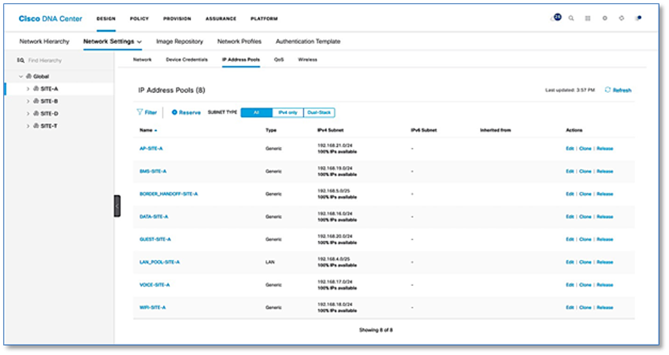
Step 2. Please refer to the Reserve IP Address Pools procedure in the Cisco SD-Access Distributed Campus PDG to add the address pools per site in Cisco DNA Center. Figure 10 below illustrates IP Pool Assignment for Site A.
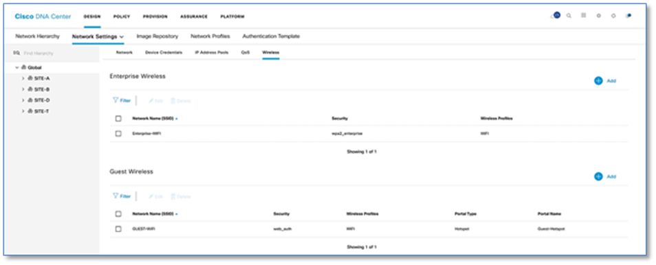
Procedure 4. Configuring enterprise & guest wireless network (SSID’s)
Step 1. Please refer to the Design Enterprise Wireless SSIDs for SD-Access Wireless procedure in the Cisco SD-Access Distributed Campus PDG to create Enterprise Wireless SSID in Cisco DNA Center.
Cisco SD-Access Distributed Campus Prescriptive Deployment Guide
Step 2. Please refer to the Design Enterprise Wireless SSIDs for SD-Access Wireless procedure in the Cisco SD-Access Distributed Campus PDG to create a Guest Wireless SSID in Cisco DNA Center. Figure 11 below illustrates Wireless SSID creation at the end of the workflow.
Cisco SD-Access Distributed Campus Prescriptive Deployment Guide
Process 5: Network Segmentation using the Policy Application
The SD-Access policy application allows the creation of fabric-wide policies to provides multiple levels of segmentation to address customer requirements. Segmentation within SD-Access is enabled through the combined use of both Virtual Networks (VN), which are synonymous with VRFs, and Cisco Scalable Group Tags (SGTs).
By default, Cisco DNA Center has a DEFAULT_VN that can be used if you do not wish to create a custom named VN. This VN always exists in a fabric and is the VN into which users, devices and things are mapped by default if no other VN is chosen.
The INFRA_VN is another default VN which always exists in a fabric where infrastructure devices such as APs and Extended Nodes are mapped into. This VN is somewhat special in that users are never mapped into this VN. It is mapped into the Global Routing Table (GRT) in the underlay on the borders, but with a LISP instance in the GRT to keep track of these infrastructure devices and their locations. INFRA_VN is also used for the PnP onboarding services for these devices through Cisco DNA Center.
The best approach to create dedicated virtual networks is to start small and grown into it. Figure 12 highlights how a typical enterprise network might be segmented. We have three Virtual Network - CAMPUS, BMS and GUEST and you will find respective scalable groups (e.g. EM, CO) within a Virtual Network.
Procedure 1. Access Control Application integration
Cisco DNA Center is now integrated with Access Control Application (ACA) to simplify group-based access control policy management directly within Cisco DNA Center. This also provides a greater level of interoperability with non-Cisco identity solutions. ACA provides the ability to classify a variety of endpoints (users, enterprise devices, IoT devices or even workloads running in private or public clouds) to be mapped into scalable groups in Cisco DNA Center. These scalable groups can then be used to define group-based access control policies in Cisco DNA Center which are deployed to Cisco ISE for distribution to a SD-Access deployment.
| Tech tip |
| This deployment guide is focused on the creation and use of VNs to provide network segmentation. This procedure is optional and not required if Scalable Group Tags will never be used for micro segmentation. It is recommended that the migration is performed. Essentially this migration will restrict all SGT and Scalable Group Policy creation to ACA only and any attempt to perform those actions at ISE will result in an error. |
Follow these optional steps to perform a one-time migration.
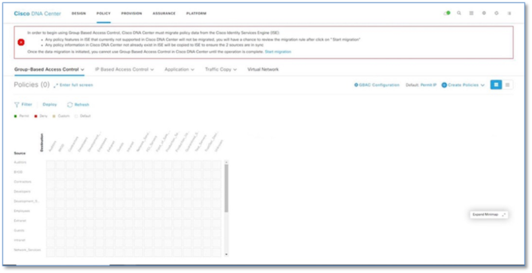
Step 1. Navigate to Policy from the Cisco DNA Center home page.
Step 2. Click on the Start Migration hyperlink within the banner.
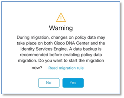
Step 3. Click Yes on warning dialog window once the migration rules are Read.
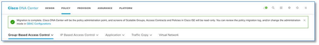
Step 4. Migration takes couple of minutes and with successful migration a new Banner pops up with Migration Complete message.
Procedure 2. Create a virtual network
You can create a virtual network to segment your physical network into multiple logical networks
Step 1. Navigate to Policy > Virtual Network from the Cisco DNA Center home page,
Step 2. Click + to create a new Virtual Network.
Step 3. In the Virtual Network Name field, enter the name of the virtual network (E.g. CAMPUS)
Step 4. (Optional) Drag and drop groups from the Available Scalable Groups area to the Groups in the Virtual Network area.
Step 5. Click Save.
Step 6. To create other virtual networks (IOT, BMS), repeat above steps.
Procedure 3. Create a Guest virtual network
In SD-Access, we can create a Guest Virtual Network as well as a dedicated Guest Border, Control Plane, and ISE PSN (Policy Services Node/RADIUS server). In this guide, we use the same Border, Control Plane, and ISE PSN as the Enterprise network.
Step 1. Navigate to Policy > Virtual Network from the Cisco DNA Center home page,
Step 2. Click + to create a new Virtual Network.
Step 3. In the Virtual Network Name field, enter the name of the virtual network (E.g. GUEST)
Step 4. Check the Guest Virtual Network check box, to configure the virtual network as a guest network.
Step 5. Click Save.
Process 6: Deploying SD-Access Fabric with the Provision Application
Once your Network Design has been defined and you have created the VNs for your network in Cisco DNA center, you can provision your devices. Provisioning devices includes the following aspects:
● Adding devices to Sites: This step involves assigning network devices from the inventory to the sites created as part of the design workflow. This makes the device ready to accept the site-specific design parameters.
● Deploying the required setting and policies to devices in the inventory: This step involves the provisioning of the configuration based on design workflow. When the provisioning step is executed, all the parameters which were set in the design for the site are provisioned to the device based on Cisco best practice recommendations.
● Creating Fabric domains and adding devices to Fabric: This step involves creating a Fabric Domain, Fabric Sites, Transit Sites and a Fabric overlay network
Procedure 1. Adding devices to sites and provisioning network settings
Please refer to the Assign Network Devices to Site and Provision Network Settings procedure in the Cisco SD-Access Distributed Campus PDG to assign network devices to sites and provision network settings in Cisco DNA Center.
Cisco SD-Access Distributed Campus Prescriptive Deployment Guide
| Tech tip |
| Here is the list of IOS XE features configured as part of the Provision process. Add AAA Configuration, Add Password Encryption Configuration, Add DNS Configuration, Add HTTP / HTTPS Server Configuration, Add NTP Configuration, Add TrustSec Configuration Add ACL Configuration |
Procedure 2. Discover fabric edge devices using LAN automation
Cisco DNA Center provides a tool that can be used to automate the deployment of the network itself. This capability employs a seed device and starting from that device can “walk out” up to two layers within the network hierarchy and automate the deployment of new devices it discovers. LAN automation is initiated only on directly connected neighbors and is intended to support the deployment of an underlay suitable later for overlay of an SD-Access fabric.
For detailed information on LAN Automation, refer to below deployment guide.
Cisco DNA Center LAN Automation Deployment Guide
Procedure 3. Configure and provision Cisco Wireless LAN Controllers at Site-A and Site-B
Catalyst 9800 Series WLCs support the ability to be configured in an active/standby high availability (HA) stateful switch-over (SSO) pair. Cisco DNA Center supports the ability to take two controllers of the same model, running the same OS version, and configure them into an HA SSO pair.
Refer to Appendix 3 for detailed steps to configure C9800-L Controllers as HA Pair, Setting Management interface for WLC and Provisioning network settings.
Process 7: Deploying Fabric/Transit Network with the Provision Application
A fabric is a logical group of devices that is managed as a single entity in one or multiple locations. Fabric enables several capabilities such as creation of virtual networks to support mobility and segmentation, users and devices groups and advanced reporting functions. Cisco DNA Center allows you to add devices to fabric network. These devices can be configured to act as control plane, border, or edge devices within the fabric Network.
Provisioning the fabric overlay involves the following steps:
● Create Fabric Domain
● Creating Fabric Sites within Fabric Domain
● Assigning and provision Fabric roles
● Host Onboarding
Procedure 1. Create an SD-Access fabric domain
A fabric domain is a logical administrative construct in Cisco DNA Center that is managed as single entity in one or multiple locations and interconnected by a transit site. This prescriptive deployment guide includes a single fabric domain that will encompass the buildings (sites) created in Design section.
Please refer to the Create a Fabric Domain detailed procedure in the Cisco SD-Access Distributed Campus PDG in Cisco DNA Center.
Cisco SD-Access Distributed Campus Prescriptive Deployment Guide
Procedure 2. Creating additional SD-Access fabric sites
A fabric site is an independent fabric area with a unique set of network devices; control plane, border node, edge node, wireless controller, ISE PSN. Different levels of redundancy and scale can be designed per site by including local resources; DHCP, AAA, DNS, Internet, and so on. A fabric site can cover a single physical location, multiple locations, or only a subset of a location as well.
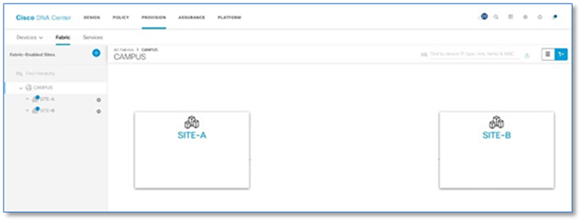
Please refer to the Add Fabric-Enabled Sites to the Fabric Domain procedure to create new fabric sites within CAMPUS fabric domain in Cisco DNA Center.
Cisco SD-Access Distributed Campus Prescriptive Deployment Guide
Procedure 3. Create a transit/peer network
A transit/peer network connects two or more fabric sites with each other or connects the fabric site with external networks; Internet, data center, and so on. There are two types of transit networks:
● IP transit: Uses a regular IP network to connect to an external network or to connect two or more fabric sites.
● SDA transit: Uses LISP/VXLAN encapsulation to connect two fabric sites. The SDA transit area may be defined as a portion of the fabric that has its own control plane nodes, but does not have edge or border nodes. However, it can work with a fabric that has an external border. Using SDA transit, an end-to-end policy plane is maintained using SGT group tags.
To create IP Transit Network:
Step 1. Navigate to Provision > Fabric from the Cisco DNA Center home page.
Step 2. Select the + button next to Add Fabric or Transit/Peer Network and select Transit/Peer Network
Step 3. Enter Name (e.g. IP_TRANSIT) for Transit/Peer Network
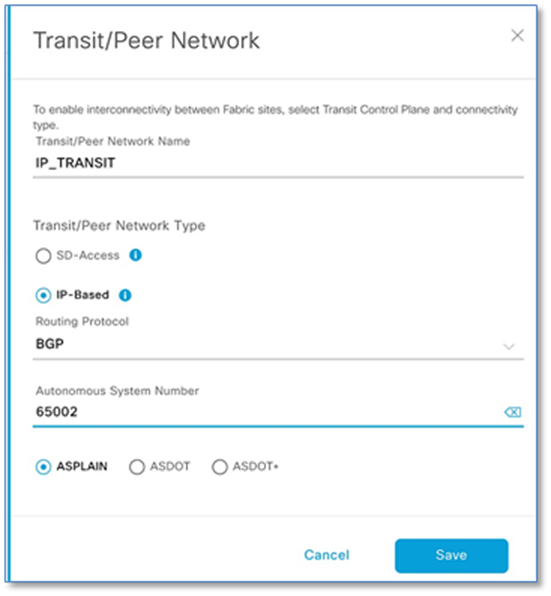
Step 4. Select IP-Based Radio Button under Transit/Peer Network Type
Step 5. Enter Autonomous System Number (e.g. 65002)
Step 6. Click Save
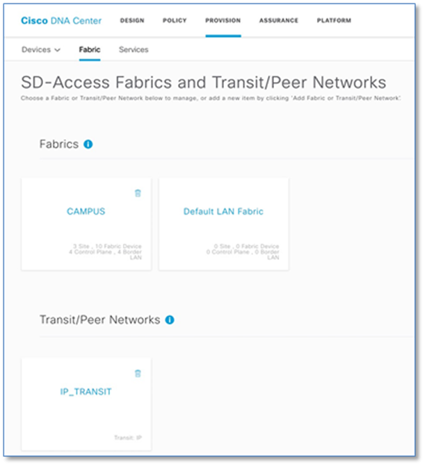
The following screenshot shows the summary of the fabric set up so far. One Fabric Domain (CAMPUS) and one Transit/Peer Networks.
Procedure 4. Provisioning fabric overlay and add device as border node at SITE-A
After you have created a fabric domain, fabric sites and transit network, next step involves selection of fabric edge, fabric border and fabric control plane nodes within the respective fabric sites to build the fabric overlay on the existing underlay network.
When provisioning a device as a border node, there are three options to indicate the type of network(s) to which the border node is connected:
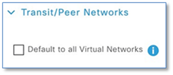
An Internal Border is connected to the known routes in the deployment such as a Data Center. As an Internal border, it will register these known routes with the site-local control plane node which directly associates these prefixes with the fabric. Unchecking the Default to all Virtual Networks sets the device as an Internal Border.
An External Border is connected to unknown routes such as the Internet, WAN, or MAN. Most networks use an external border, for a common exit point from a fabric, such as for the rest of an enterprise network along with the Internet. The external border is an efficient mechanism to offer a default exit point to all virtual networks in the fabric, without importing any external routes. This is the default border type on the DNA Center 1.3.3.1 release.
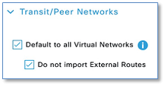
An Anywhere Border is used when the network uses one set of devices to egress the site. It is directly connected to both known and unknown routes. A border node connected to an SD-Access transit may use this option if it is also connected to a fusion router to provide access to shared services. Unchecking the Do not import External Routes checkbox sets the device as Anywhere Border (Internal + External)
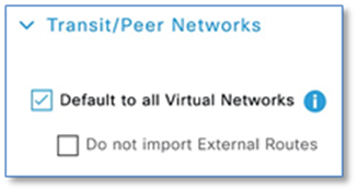
As part of this prescriptive deployment guide and the topology used, we will be using an External Border as it’s the only explicit exit point out from the fabric site and we don’t need to import any of the external networks into the VNs in the Fabric.
After you have created a fabric domain, fabric sites and transit/peer networks, the next step is to add devices to the fabric and specify whether the device should act as a control plane node, an edge node or a border node.
The Control plane function is either co-located on a single device with fabric border functions or implemented on a dedicated device for the control plane node. Dedicating a device for control plane only function results in greater scalability and improved fault tolerance. In this prescriptive deployment guide, we have chosen to implement a collocated fabric control plane/border node set of functions on a common device for SITE-A and SITE-B.
As discussed in the Design Section, due to lack of physical interfaces on the fusion router, just one link (Layer 3) was used for connectivity between border and fusion devices. For Cisco DNA Center border automation, the border interface connecting to the Fusion device has to be a layer 2 interface (Layer 2). This is completed using the default interface command. Reachability of Primary Border(A-9500-32C) is still available through Peer Border(A-9500-32QC). This is depicted earlier in Figure 5.
Step 1. Log into the primary border node and enter configuration mode. Issue the following command on the interface connecting to your fusion router.
A-9500-32C(config)#default interface hu1/0/3
Step 2. Synchronize the device for Cisco DNA Center to collect the latest device configuration. Navigate to Provision > Network Devices > Inventory then select the device and click the Actions drop-down. Select Inventory > Resync Device.
Step 3. Add the device as Border Node. Navigate to Provision > Fabric from the Cisco DNA Center menu.
Step 4. From the list of fabric domains Choose CAMPUS.
Step 5. Choose SITE-A. All devices in the network that have been inventoried/provisioned are displayed.
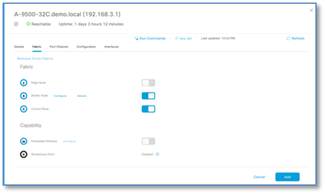
Step 6. Select A-9500-32C, Click the toggle button next to Border Node to enable the selected device as a border node.
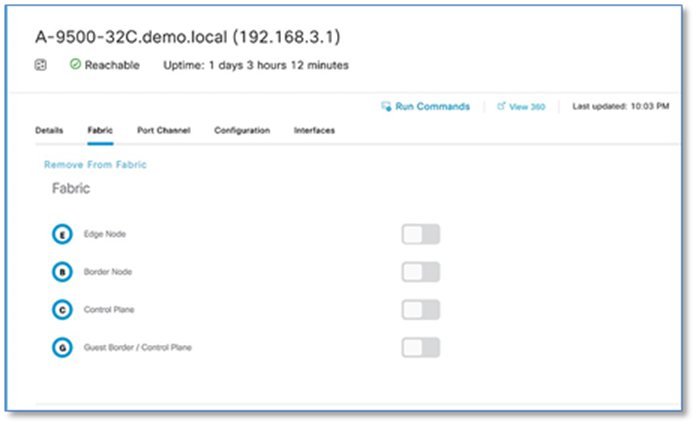
Step 7. A slide-in window appears with name of the device and expanded Layer 3 Handoff.
Step 8. With ASPLAIN radio button selected, key in the BGP Local Autonomous Number = 65001
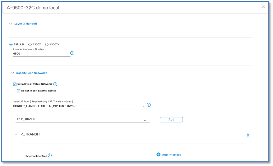
Step 9. By default, a border node is designated as External Border.
Step 10. In Select IP Pool field, Use the drop down to select the Border Handoff Pool (For SITE-A: BORDER_HANDOFF-SITE-A pool) for Cisco DNAC to automate VRF-Lite and BGP handoff between the border and upstream device, in our case ISR4K.
| Tech Tip |
| During the Layer-3 border handoff automation, Cisco DNA Center uses VLSM on the defined Border Handoff address pool to create multiple /30 subnets. Each subnet is associated with a VLAN beginning at 3001. Cisco DNA Center does not currently support the reuse of VLANs when a device is provisioned and un-provisioned. The VLAN number will continue to advance as demonstrated in the screen captures. |
Step 11. In Select Transit/Peer Network, use drop down to select IP: IP_TRANSIT and Click ADD to add the transit network
Step 12. Click on drop down next to previously configured IP_TRANSIT to add external interface on the border connecting to the upstream ISR Routers.
Step 13. Click + next to Add Interface to enter interface details on new slide-in pane.
Step 14. Choose the External interface from the drop-down list connected to first fusion device (e.g. hu 1/0/3)
Step 15. Select all virtual networks which should be advertised by the border to the fusion device. You can select one, multiple or all virtual networks.
Step 16. Click Save to exit the Add Interface slide-in plane.
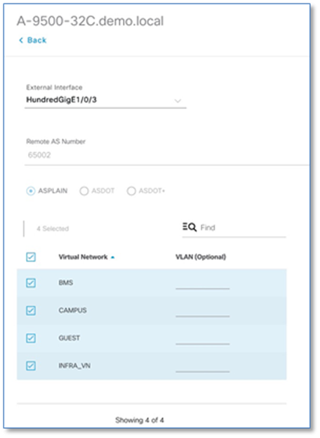
| Tech Tip |
| Starting with Cisco DNA Center release 1.3.3.1, the UI allows you to set the VLAN-Id manually for the VRF-Lite Handoff between the border and fusion device. If left to default, Cisco DNA Center will provision VLAN starting at 3001 and incrementing up to VLAN 3500 depending on number of virtual networks. |
| Tech Tip |
| The INFRA_VN is described in the next process. It is associated with the global routing table – it is not a VRF definition – and is used by access points and extended nodes. If these devices require DHCP, DNS, and other shared services, the INFRA_VN should be selected under Virtual Network. |
Step 17. Click Add button at the bottom to complete the border node workflow.
Step 18. Next to Control Plane function on the same device, click the toggle button next to Control Plane as show in screenshot then click Add.
Step 19. Click Save and Apply to initiate the Fabric Provisioning.
Procedure 5. [Optional] – Provision Redundant Border handoff
In case of Full Mesh connectivity between Border Node and Fusion device, follow the steps below to edit the current border configuration.
Step 1. Navigate to Provision > Fabric > CAMPUS > SITE-A and select Border Node and Click Configure
Step 2. Under Transits, click > to expand the previously defined IP Transit.
Step 3. Click + Add Interface to add 2nd external Interface
Step 4. Select the External Interface from the new slide-in pane and select required virtual networks.
Step 5. Click Save.
Step 6. Click Add and Apply.
Procedure 6. Add device as edge node – SITE-A
To add a device as an edge node.
Step 1. Navigate to Provision > Fabric from the Cisco DNA Center home page.
Step 2. From the list of fabric domains Choose CAMPUS fabric domain. Screen displays all the sites in the fabric domain.
Step 3. Choose SITE-A.
Step 4. Select edge device (e.g. A-9300-24P), Click the toggle button next to Edge Node to enable the select device as an edge node.
Step 5. Click Add
Step 6. Repeat the above steps for other edge nodes at SITE-A.
Step 7. Click Save and Apply
Procedure 7. Add redundant device as a border node at SITE-A
As stated in the Design section, to ease the migration process, it’s recommended to have two links between Border Node and Fusion device. This avoids having to perform the following, temporary configuration, for reachability to other fabric devices prior to adding the redundant device as a border node.
Cisco DNA Center, as part of border automation, configures the interface connecting to the fusion device.
Step 1. Navigate to Provision > Fabric > CAMPUS (fabric domain) > SITE-A fabric Site.
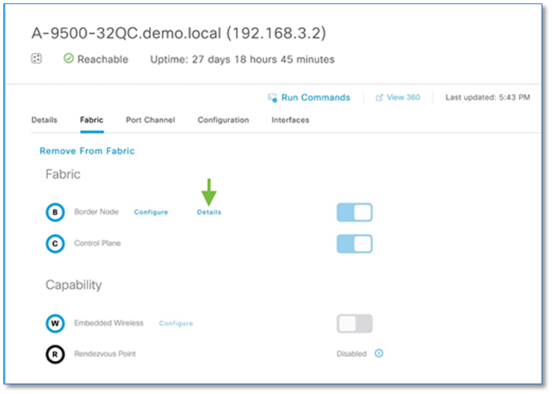
Step 2. Click on the fabric border (A-9500-32C) which was provisioned earlier.
Step 3. Click Details link next to border node and Click > to expand the information. The Layer-3 handoff provisioning information is displayed along with the Local IPs and necessary Remote IPs.
Step 4. To establish a temporary OSPF neighbor relationship between A-9500-32C border and Fusion device (A-ISR4431) on INFRA_VN SVI execute the following CLI.
Device: A-9500-32C
router ospf 1
network 192.168.5.12 0.0.0.3 area
Device: A-ISR4431
default interface GigabitEthernet 0/0/2
!
interface GigabitEthernet 0/0/2
mtu 9100
no shut
!
interface GigabitEthernet0/0/2.3004
encapsulation dot1Q 3004
ip address 192.168.5.14 255.255.255.252
!
router ospf 1
network 192.168.5.12 0.0.0.3 area 0
Step 5. Repeat the steps in Procedure 4 to add the redundant Border to Fabric.
Procedure 8. Add device as border node and fabric edges at SITE-B
Follow the steps in Procedure 4 and Procedure 6 to add the switches at SITE-B as border node & fabric edges.
Procedure 9. Add WLC to fabric at SITE-A
To add a Cisco Wireless LAN Controller to fabric:
Step 1. Navigate to Provision > Fabric from the Cisco DNA Center menu.
Step 2. From the list of fabric domains Choose CAMPUS. Screen displays all the sites in the fabric domain.
Step 3. Choose SITE-A.
Step 4. Select controller (A-9800-L-1), click the toggle button next to Wireless to add to the fabric.
Step 5. Click Add
Step 6. Click Save
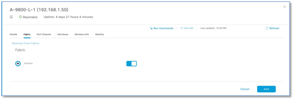
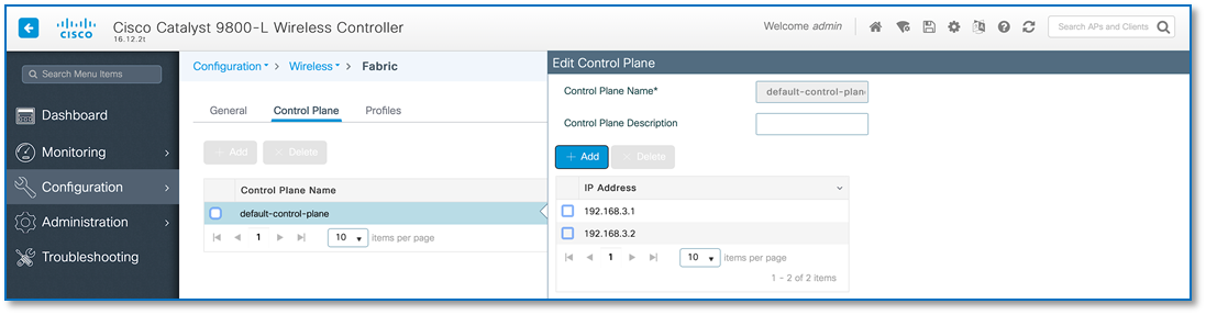
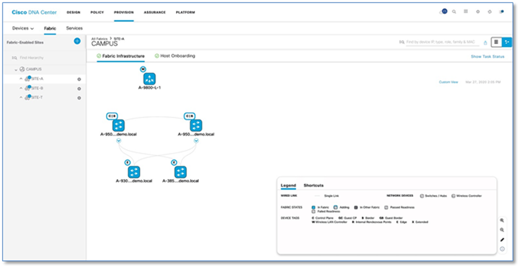
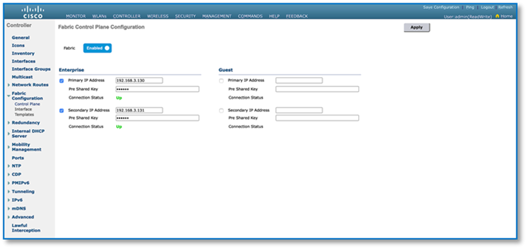
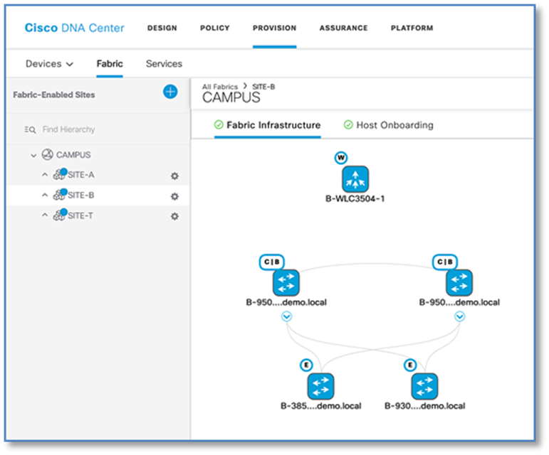
Figure 29 confirms the insertion of the Fabric Control Plane Node IP addresses into the WLC configuration while Figure 30 confirms the C9800 Wireless LAN Controller addition into the fabric at Site A and. Figure 31 and 32 reflects an AireOS based controller addition into the Fabric at Site B.
Process 8: Configuring Host Onboarding with PROVISION Application
The Host Onboarding tab lets you configure settings for the various kinds of devices or hosts that can access the fabric domain. The Host onboarding workflow allows you to authenticate (Statically or Dynamically), classify and assign an endpoint to a scalable group and then associate an IP Pool to a Virtual Network.
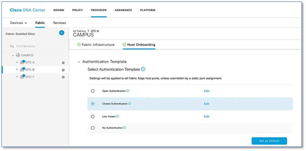
Procedure 1. Authentication template selection.
These templates are predefined configurations which automatically push the required configurations to all Fabric Edges. Below are four authentication templates available to choose from:
● Open Authentication (Monitor-Mode): A host is allowed network access without having to go through 802.1X authentication.
● Closed Authentication: Any traffic prior to authentication is dropped, including DHCP, DNS, and ARP.
● Low Impact: Security is added by applying an ACL to the switch port, to allow very limited network access prior to authentication. After a host has been successfully authenticated, additional network access is granted.
● No Authentication.
Follow the steps below to define the Closed Authentication Template for the SITE-B fabric:
Step 1. Navigate to Provision > Fabric from the Cisco DNA Center menu.
Step 2. From the list of fabric domains, Select CAMPUS fabric domain.
Step 3. From the list of fabric-enabled Sites, select SITE-B fabric site
Step 4. Click on Host Onboarding tab
Step 5. Click > symbol next to Authentication Template to drop down the authentication templates supported.
Step 6. Select Closed Authentication radio button and click on Set as Default button to save the template. The Edit hyperlink next to the template allows to change the order of authentication methods, 802.1x to MAB Fallback timer, Wake on LAN, and Number of hosts (Multi-Auth vs Single-Host). Leave it as default for now.
Step 7. Repeat the steps above for configuring global template for SITE-A Fabric as well.
| Tech tip |
| Beginning with Cisco DNA Center Release 1.3.3.x, the hitless authentication change feature lets you switch from one authentication method to another without removing the devices from the fabric. |
Procedure 2. Associate IP address pools to virtual networks
This procedure associates unicast or multicast IP address pools to virtual networks (default, guest, or user defined). The IP address pools displayed are site-specific pools only. When an IP address pool is associated to virtual network, Cisco DNA Center immediately connects to each fabric edge node to create the appropriate switch virtual interface (SVI) for host communications.
Follow the steps below to associate IP address Pool to Virtual Network for the SITE-A fabric.
Step 1. Navigate to Provision > Fabric from the Cisco DNA Center menu.
Step 2. From the list of fabric domains, Select CAMPUS fabric domain.
Step 3. From the list of fabric-Enabled Sites, Select SITE-A fabric Site
Step 4. Click on Host Onboarding tab
Step 5. Click > symbol next to Virtual Network to display VN created in Policy section.
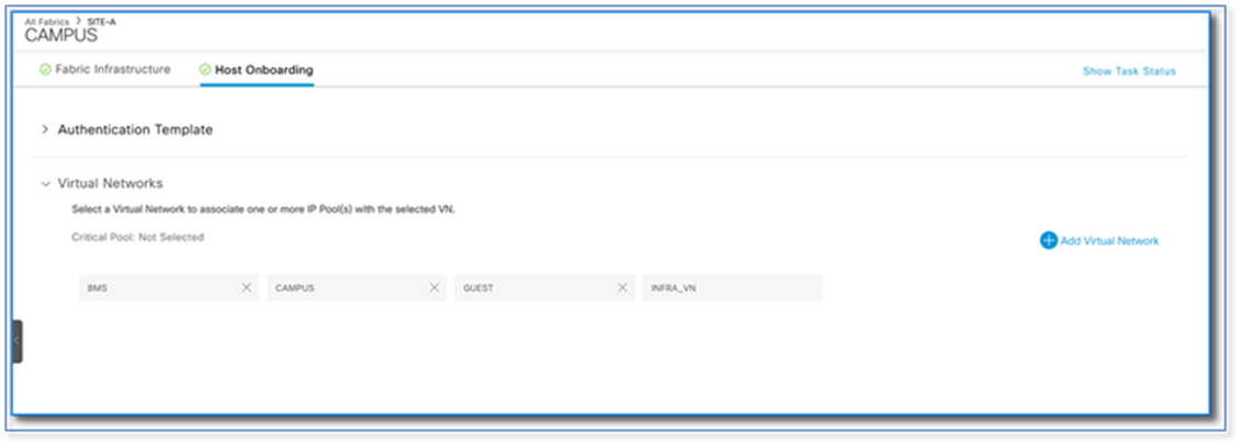
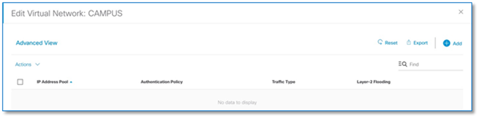
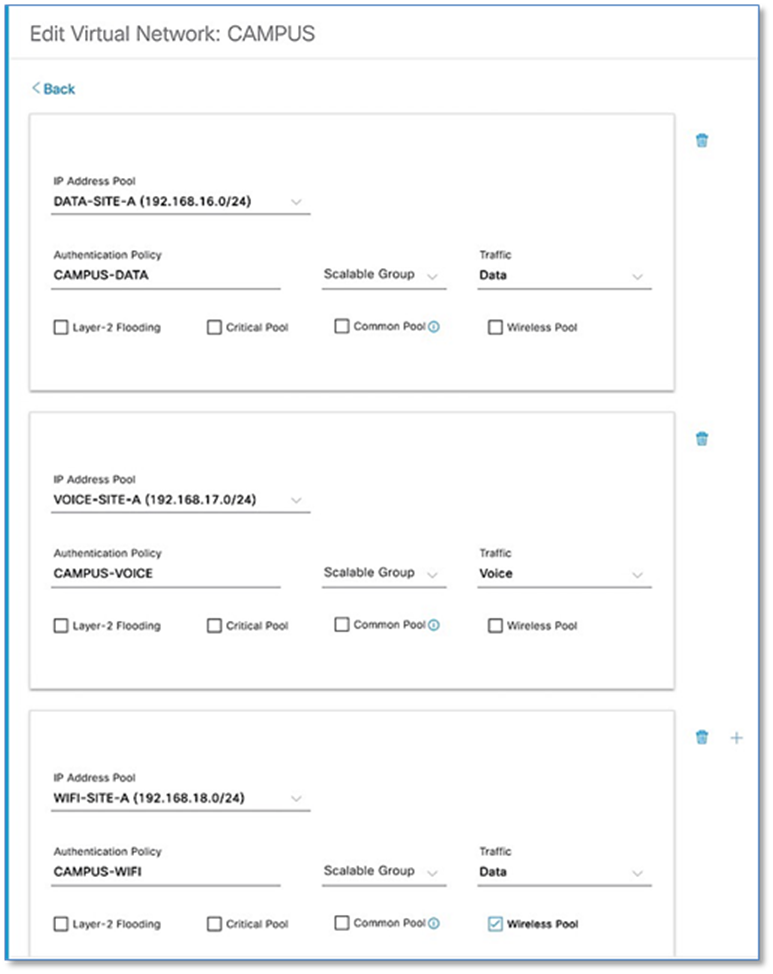
Step 6. Select CAMPUS virtual network to associate the IP pool for Wired Clients.
Step 7. In Edit Virtual Network Window, click Add to associate an IP address pool to the selected virtual network.
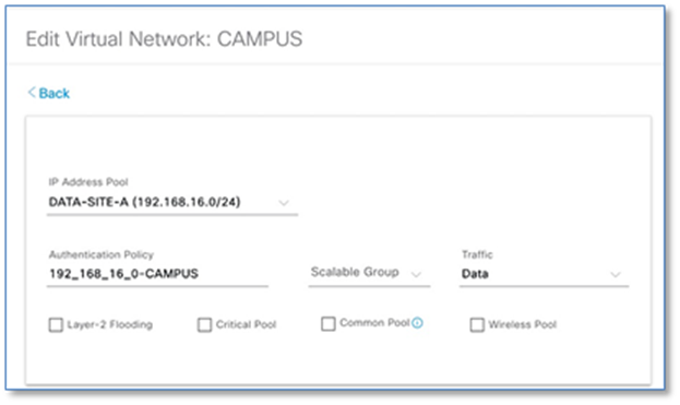
Step 8. Fill in the required fields as shown in Screenshot below and click Add. Edit the Authentication Policy Field to give a meaningful VLAN Name as shown in the second Screen Shot below. Use the + symbol to associate multiple IP address Pool to VN.
| Tech tip |
| Cisco DNA Center generates well-formatted VLAN names when deploying an IP pool to a VN. The format is ([IP_Pool_Subnet]-[Virtual_Network_Name]), where the subnet octets are separated by underscores, not decimals. Refer to Figure 35. Edit the well-formatted VLAN name to a name which can be used in common across multiple sites with multiple address pools to minimize the number of policies and authorization profiles required per Fabric Site on Cisco ISE. Consistent use of VLAN name can be used regardless of IP Pool. Refer to Figure 36. |
Step 9. Click Add then Save
| Tech tip |
| Number of IP pools supported per site varies from 100 to 600 pools depending on the model of DNAC appliance. Cisco DNA Center 1.3.3.0 Appliance: Scale and Hardware Specifications |
Step 10. Repeat the above steps for Enterprise-Wifi pool with the additional step to enable the selected IP pool as a wireless pool. Refer to Figure 37.
| Tech Tip |
| Wireless Pool check box solves two problem: · Reduces the number of IP Pools Wireless LAN Controllers need to keep track. · Only Wireless Pools to be available for SSID to IP Pool Association. |
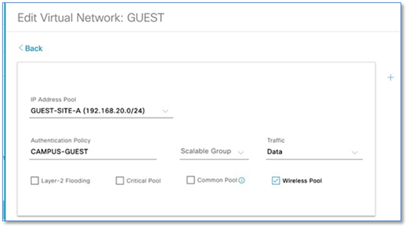
Step 11. Repeat above steps to associate IP address pool for the BMS and Guest virtual networks.
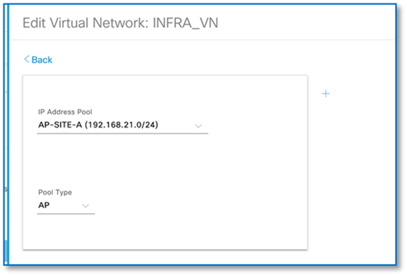
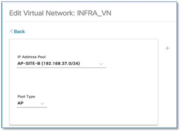
An additional VN that exists by default within an SD-Access deployment is the INFRA_VN (Infrastructure VN), into which network infrastructure devices such as access points and extended node switches are mapped. This VN is “special” as users are never mapped into this VN.
Step 12. Follow the steps above to associate the IP Pools for the Access Points in each of the two sites in the INFRA_VN and choose AP as Pool Type. Refer to the screenshots below.
Procedure 3. Associating IP address pool to SSID
Follow the steps below to associate IP address pools for SSIDs (Guest or Enterprise SSIDs) defined earlier
Step 1. Navigate to Host Onboarding > Wireless SSID’s section as seen in Figure 40 below.
Step 2. Click Choose Pool drop down and select an IP pool reserve for the GUEST-WIFI and ENTERPRISE-WIFI SSID as shown in screenshot below.

Step 3. Click Save and Apply.
Step 4. Repeat IP pool assignment for SSIDs in the other sites(s).
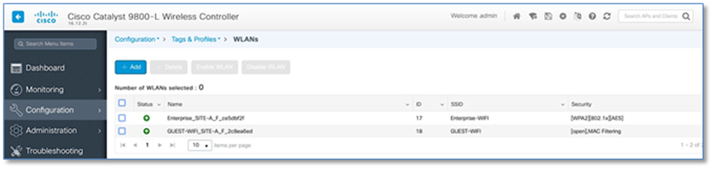
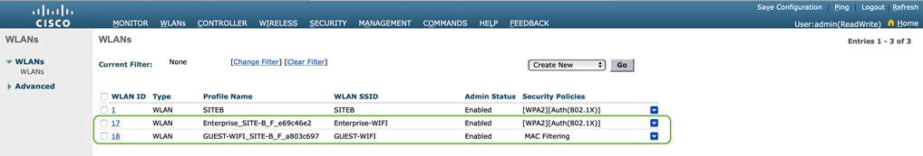
Step 5. With above configuration, WLAN Status on the C9800 Wireless LAN Controllers should move to UP State. From the Site-A and Site-B Catalyst 9800 user interfaces, navigate to Configuration > Tags & Profiles > WLAN.
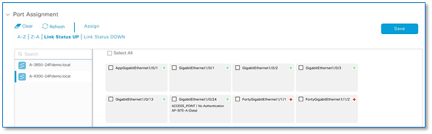
Procedure 4. Port assignment
Individual port assignments apply specific configurations to a port based on a type of device that is connected to that port. Settings here override the authentication template selected globally.
As part of this topology, with the closed authentication template selected globally, no port assignment changes are required for connection of user devices. However, changes are required for those ports that Access Points will be connected to.
Procedure 2 Step 12 above, automatically pushes a configuration macro to all the Fabric Edge switches. Cisco APs connected to a switchport will be recognized as an Access Point through CDP and the macro will be applied to the port automatically while assigning the physical port to the right VLAN. The CDP macro on the Fabric Edges for AP onboarding is pushed only if the no-authentication template is selected globally. Since the globally selected template is closed authentication, follow below steps to override the global configuration via port assignment.
Step 1. Navigate to Provision > Fabric from the Cisco DNA Center menu.
Step 2. From the list of fabric domains, Select CAMPUS fabric domain.
Step 3. From the list of fabric-enabled Sites, Select SITE-A fabric Site
Step 4. Click on Host Onboarding tab
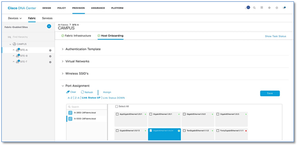
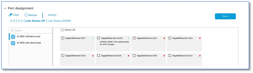
Step 5. Under Port Assignment (Refer to Figure 43), Select an Edge Node (e.g. A-9300-24P) to which the AP is connected
Step 6. Click Link Status UP hyperlink to display the ports which are in UP state on TOP.
Step 7. Select the check box of the interface (e.g. GigabitEthernet1/0/24) to which Access Point is connected
Step 8. Click Assign
Step 9. In the Port Assignment slide pane, select Access Point (AP) under Connected Device Type and leave all other to prepopulated defaults. Refer to Figure 44
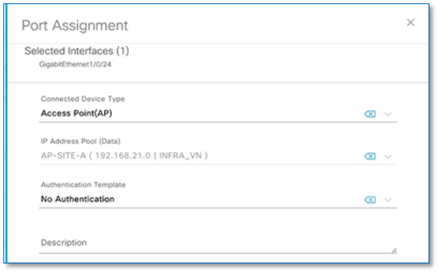
Step 10. Click Update, Save and Apply
Step 11. Repeat above procedure for access point at SITE-B
| Tech tip |
| Fabric constraints related to Host Onboarding: · Cisco SD-Access deployments support only APs, extended nodes, user devices (such as a single computer or a single computer plus phone), and single servers. · Each port can learn up to a maximum of 10 MAC addresses due to IPDT config pushed by DNAC. · Servers with internal switches or virtual switches are not supported. · Other networking equipment (such as hubs, routers, and switches) is not supported. |
Process 9: Providing Access to Shared Services via IP Transit
As part of Fabric Overlay workflow, VNs defined and created were provisioned to the Fabric devices in the form of VRF definitions and LISP Instance Id’s. Later in the Host Onboarding workflow, IP pools for respective traffic types were associated to virtual networks.
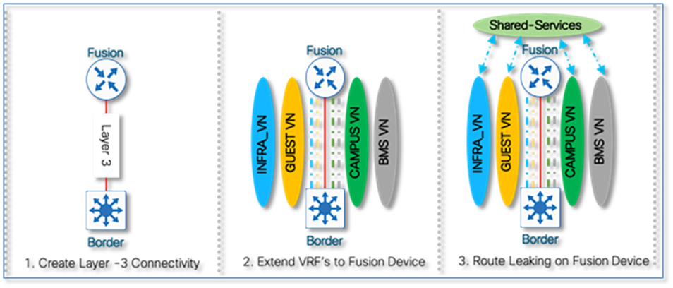
Shared Services such as DHCP and DNS hosted in the data center will generally reside outside of SD-Access fabric. Several design considerations apply, depending on whether the shared services reachable via the Global routing table (GRT) or located in another VRF. Hence, we need a method to advertise these shared services routes from the GRT/VRF to the VN routing tables on the border nodes so that endpoints in the fabric can access them. This is accomplished using Fusion devices/IP Transit network.
As part of the topology used in this prescriptive deployment guide, shared services resides in the GRT and hence we will extend the VRF definitions to Fusion Device to enable the leaking of routes between the various VRFs to GRT and shared services routes to the VRFs for both fabric Sites.
Access to shared services is a multi-step workflow performed primarily on the command-line interface of the fusion device.
● Create the VRF-Lite connectivity between fusion device and border node.
● Establish BGP peering per VRF/GRT between fusion device and the border node.
● Perform two-way route leaking between VRF to GRT and vice versa on fusion device
Procedure 1. Configuring VRF definitions to fusion devices
As part of the fabric overlay provisioning workflow, Cisco DNA Center automates VRF, VRF-Lite connectivity and BGP configuration on the border node. We can leverage the VRF configuration on the Border node to extend the VRFs to the Fusion device.
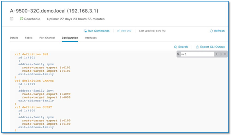
The VRF configuration on the border node can be retrieved using device’s CLI, Command Runner tool or through the Inventory device configuration on the Cisco DNA Center. To use Inventory device configuration option to display the border node VRF configuration, follow the below steps
Step 1. Navigate to Provision > Fabric from the Cisco DNA Center menu.
Step 2. From the list of fabric domains, select CAMPUS fabric domain.
Step 3. From the list of fabric-enabled sites, select SITE-A fabric Site
Step 4. Click on the border node (A-9500-32C) and in the slide-in window, click on configuration tab to view the Border node configuration.
Step 5. Click on Search and type in VRF. Scroll up to view vrf definition. Refer to Figure 48
Step 6. Copy 3 VRF definition as is and paste it on the both Fusion devices.
Procedure 2. Configuring VRF-Lite connectivity on fusion devices.
As part of the fabric overlay provisioning workflow, Cisco DNA Center provisions a VRF-Lite configuration on the border nodes. The following steps will create the corresponding VRF-Lite configuration on the fusion device. We will leverage the configuration on the Border node to determine the corresponding configuration needed on the fusion device.
Step 1. Navigate to Provision > Fabric from the Cisco DNA Center menu.
Step 2. From the list of fabric domains, select CAMPUS fabric domain.
Step 3. From the list of fabric-enabled sites, select SITE-A fabric Site
Step 4. Click on the border node (A-9500-32C) and in the slide-in window
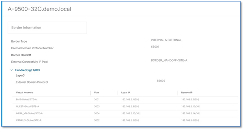
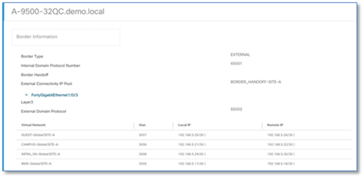
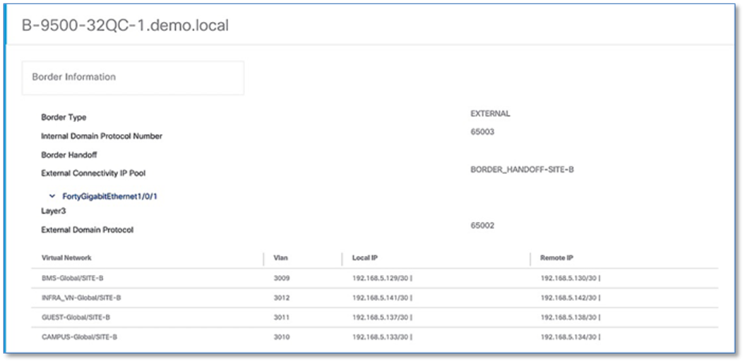
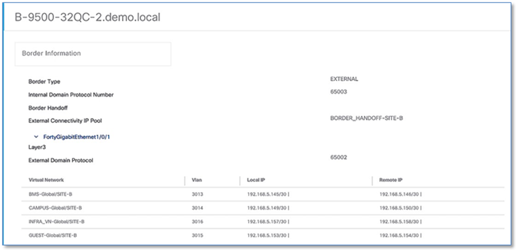
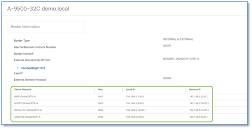
Step 5. In the slide-in window, click on the Details link next to border node for the Border information slide-in window.
Step 6. Click > to expand the information on external interface to display VN, Vlan IDs, Local IP and Remote IP. Note this information as this will be used in the next step to build the fusion device configuration.
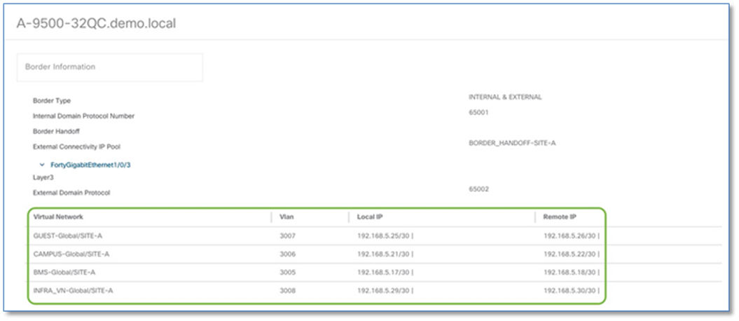
Step 7. Repeat the steps above to collect information of the redundant border node (A-9500-32QC)
The fusion device can be a Cisco router, switch or firewall. This deployment guide uses a pair of ISR 4K routers as fusion devices common to both SITE-A and SITE-B. The VRF-Lite configuration will therefore utilize sub-interfaces on the router side while Cisco DNA Center has already provisioned VLANs, SVIs and trunk ports on the border nodes to extend the VRFs.
The following steps will use the IP address and VLAN information from the Border Node Handoff Information. Refer to Figure 50 and 51.
Step 8. Configure the sub-interfaces on fusion device towards connecting to the Site A border node.
Device: T-ISR4431
interface GigabitEthernet0/0/3
description *** 1G link to A-9500-32C Hun 1/0/3 ***
mtu 9100
!
interface GigabitEthernet0/0/3.3001
encapsulation dot1Q 3001
vrf forwarding BMS
ip address 192.168.5.2 255.255.255.252
!
interface GigabitEthernet0/0/3.3002
encapsulation dot1Q 3002
vrf forwarding CAMPUS
ip address 192.168.5.6 255.255.255.252
!
interface GigabitEthernet0/0/3.3003
encapsulation dot1Q 3003
vrf forwarding GUEST
ip address 192.168.5.10 255.255.255.252
| Tech Tip |
| INFRA_VN (3004) was previously configured for fusion device 1. Hence ignoring the configs here. |
Step 9. Verify IP connectivity between the fusion device and the border nodes using ping commands
Device: T-ISR4431
ping vrf BMS 192.168.5.1
ping vrf CAMPUS 192.168.5.5
ping vrf GUEST 192.168.5.9
ping 192.168.5.13
Step 10. Configure the redundant fusion device’s sub-interfaces connected to the Site A redundant border node.
Device: T-ISR4432
default interface GigabitEthernet0/0/3
!
interface GigabitEthernet0/0/3
description *** 1G link to A-9500-32QC Fo1/0/3 ***
mtu 9100
no shutdown
!
interface GigabitEthernet0/0/3.3005
encapsulation dot1Q 3005
vrf forwarding BMS
ip address 192.168.5.18 255.255.255.252
!
interface GigabitEthernet0/0/3.3006
encapsulation dot1Q 3006
vrf forwarding CAMPUS
ip address 192.168.5.22 255.255.255.252
!
interface GigabitEthernet0/0/3.3007
encapsulation dot1Q 3007
vrf forwarding GUEST
ip address 192.168.5.26 255.255.255.252
!
interface GigabitEthernet0/0/3.3008
encapsulation dot1Q 3008
ip address 192.168.5.30 255.255.255.252
Step 11. Verify IP connectivity between the fusion device and the border node using ping commands
Device: T-ISR4432
ping vrf BMS 192.168.5.17
ping vrf CAMPUS 192.168.5.21
ping vrf GUEST 192.168.5.25
ping 192.168.5.29
Step 12. Configure sub-interfaces on fusion device connected to the Site B border Node.
Device: T-ISR4431
interface GigabitEthernet0/0/2
description *** 1G link to B-9500-32QC-1 Fo1/0/1 ***
mtu 9100
!
interface GigabitEthernet0/0/2.3009
encapsulation dot1Q 3009
vrf forwarding BMS
ip address 192.168.5.130 255.255.255.252
bfd interval 100 min_rx 100 multiplier 3
no bfd echo
!
interface GigabitEthernet0/0/2.3010
encapsulation dot1Q 3010
vrf forwarding CAMPUS
ip address 192.168.5.134 255.255.255.252
bfd interval 100 min_rx 100 multiplier 3
no bfd echo
!
interface GigabitEthernet0/0/2.3011
encapsulation dot1Q 3011
vrf forwarding GUEST
ip address 192.168.5.138 255.255.255.252
bfd interval 100 min_rx 100 multiplier 3
no bfd echo
!
interface GigabitEthernet0/0/2.3012
encapsulation dot1Q 3012
ip address 192.168.5.142 255.255.255.252
bfd interval 100 min_rx 100 multiplier 3
no bfd echo
Step 13. Verify IP connectivity between the fusion device and the border node using ping commands.
Device: T-ISR4431
ping vrf BMS 192.168.5.129
ping vrf CAMPUS 192.168.5.133
ping vrf GUEST 192.168.5.137
ping 192.168.5.141
Step 14. Configure the redundant fusion device connected to the Site B redundant border node.
Device: T-ISR4432
default interface GigabitEthernet0/0/2
!
interface GigabitEthernet0/0/2
description *** 1G link to B-9500-32QC-2 Fo1/0/1 ***
mtu 9100
no ip address
negotiation auto
!
interface GigabitEthernet0/0/2.3013
encapsulation dot1Q 3013
vrf forwarding BMS
ip address 192.168.5.146 255.255.255.252
bfd interval 100 min_rx 100 multiplier 3
no bfd echo
!
interface GigabitEthernet0/0/2.3014
encapsulation dot1Q 3014
vrf forwarding CAMPUS
ip address 192.168.5.150 255.255.255.252
bfd interval 100 min_rx 100 multiplier 3
no bfd echo
!
interface GigabitEthernet0/0/2.3015
encapsulation dot1Q 3015
vrf forwarding GUEST
ip address 192.168.5.154 255.255.255.252
bfd interval 100 min_rx 100 multiplier 3
no bfd echo
!
interface GigabitEthernet0/0/2.3016
encapsulation dot1Q 3016
ip address 192.168.5.158 255.255.255.252
bfd interval 100 min_rx 100 multiplier 3
no bfd echo
Step 15. Verify IP connectivity between the fusion device and the border node using ping commands
Device: T-ISR4432
ping vrf BMS 192.168.5.145
ping vrf CAMPUS 192.168.5.149
ping vrf GUEST 192.168.5.153
ping 192.168.5.157
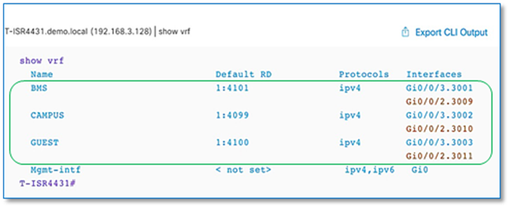
Step 16. Verify VRF-Lite connectivity on fusion devices.
Procedure 3. Establish BGP adjacencies between fusion devices and border nodes
Now that IP connectivity has been established and verified, BGP peering can be created between the fusion routers and the border nodes.
Step 1. Configure the BGP routing process on primary fusion device (T-ISR4431) connected to the Site A Border Node.
Step 1. Use the corresponding autonomous-system defined in the IP-based transit. As a recommended practice, the Loopback 0 interface is used as the BGP router ID and set the update source as respective sub-interface.
Device: T-ISR4431
router bgp 65002
bgp router-id interface Loopback0
bgp log-neighbor-changes
bgp graceful-restart
neighbor 192.168.5.13 remote-as 65001
neighbor 192.168.5.13 update-source Gi0/0/3.3004
!
address-family ipv4
bgp aggregate-timer 0
network 192.168.3.128 mask 255.255.255.255
neighbor 192.168.5.13 activate
exit-address-family
!
address-family ipv4 vrf BMS
bgp aggregate-timer 0
neighbor 192.168.5.1 remote-as 65001
neighbor 192.168.5.1 update-source Gi0/0/3.3001
neighbor 192.168.5.1 activate
exit-address-family
!
address-family ipv4 vrf CAMPUS
bgp aggregate-timer 0
neighbor 192.168.5.5 remote-as 65001
neighbor 192.168.5.5 update-source Gi0/0/3.3002
neighbor 192.168.5.5 activate
exit-address-family
!
address-family ipv4 vrf GUEST
bgp aggregate-timer 0
neighbor 192.168.5.9 remote-as 65001
neighbor 192.168.5.9 update-source Gi0/0/3.3003
neighbor 192.168.5.9 activate
exit-address-family
Step 2. Configure the BGP routing process on the redundant fusion device connected to the Site A redundant border node.
Device: T-ISR4432
router bgp 65002
bgp router-id interface Loopback0
bgp log-neighbor-changes
bgp graceful-restart
neighbor 192.168.5.29 remote-as 65001
neighbor 192.168.5.29 update-source Gi0/0/3.3008
!
address-family ipv4
bgp aggregate-timer 0
network 192.168.3.129 mask 255.255.255.255
neighbor 192.168.5.29 activate
exit-address-family
!
address-family ipv4 vrf BMS
bgp aggregate-timer 0
neighbor 192.168.5.17 remote-as 65001
neighbor 192.168.5.17 update-source Gi0/0/3.3005
neighbor 192.168.5.17 activate
exit-address-family
!
address-family ipv4 vrf CAMPUS
bgp aggregate-timer 0
neighbor 192.168.5.21 remote-as 65001
neighbor 192.168.5.21 update-source Gi0/0/3.3006
neighbor 192.168.5.21 activate
exit-address-family
!
address-family ipv4 vrf GUEST
bgp aggregate-timer 0
neighbor 192.168.5.25 remote-as 65001
neighbor 192.168.5.25 update-source Gi0/0/3.3007
neighbor 192.168.5.25 activate
exit-address-family
Step 3. Configure the BGP Routing process on fusion device connected to the Site border node.
Device: T-ISR4431
router bgp 65002
neighbor 192.168.5.141 remote-as 65003
neighbor 192.168.5.141 update-source GigabitEthernet0/0/2.3012
neighbor 192.168.5.141 fall-over bfd
!
address-family ipv4
neighbor 192.168.5.141 activate
exit-address-family
!
address-family ipv4 vrf BMS
neighbor 192.168.5.129 remote-as 65003
neighbor 192.168.5.129 update-source GigabitEthernet0/0/2.3009
neighbor 192.168.5.129 fall-over bfd
neighbor 192.168.5.129 activate
exit-address-family
!
address-family ipv4 vrf CAMPUS
neighbor 192.168.5.133 remote-as 65003
neighbor 192.168.5.133 update-source GigabitEthernet0/0/2.3010
neighbor 192.168.5.133 fall-over bfd
neighbor 192.168.5.133 activate
exit-address-family
!
address-family ipv4 vrf GUEST
neighbor 192.168.5.137 remote-as 65003
neighbor 192.168.5.137 update-source GigabitEthernet0/0/2.3011
neighbor 192.168.5.137 fall-over bfd
neighbor 192.168.5.137 activate
exit-address-family
Step 4. Configure BGP routing process on redundant fusion device connected to the Site B redundant border node.
Device: T-ISR4432
router bgp 65002
neighbor 192.168.5.157 remote-as 65003
neighbor 192.168.5.157 update-source GigabitEthernet0/0/2.3016
neighbor 192.168.5.157 fall-over bfd
!
address-family ipv4
neighbor 192.168.5.157 activate
exit-address-family
!
address-family ipv4 vrf BMS
neighbor 192.168.5.145 remote-as 65003
neighbor 192.168.5.145 update-source GigabitEthernet0/0/2.3013
neighbor 192.168.5.145 fall-over bfd
neighbor 192.168.5.145 activate
exit-address-family
!
address-family ipv4 vrf CAMPUS
neighbor 192.168.5.149 remote-as 65003
neighbor 192.168.5.149 update-source GigabitEthernet0/0/2.3014
neighbor 192.168.5.149 fall-over bfd
neighbor 192.168.5.149 activate
exit-address-family
!
address-family ipv4 vrf GUEST
neighbor 192.168.5.153 remote-as 65003
neighbor 192.168.5.153 update-source GigabitEthernet0/0/2.3015
neighbor 192.168.5.153 fall-over bfd
neighbor 192.168.5.153 activate
exit-address-family
Procedure 4. Verify BGP neighbor establishment between the fusion and border nodes
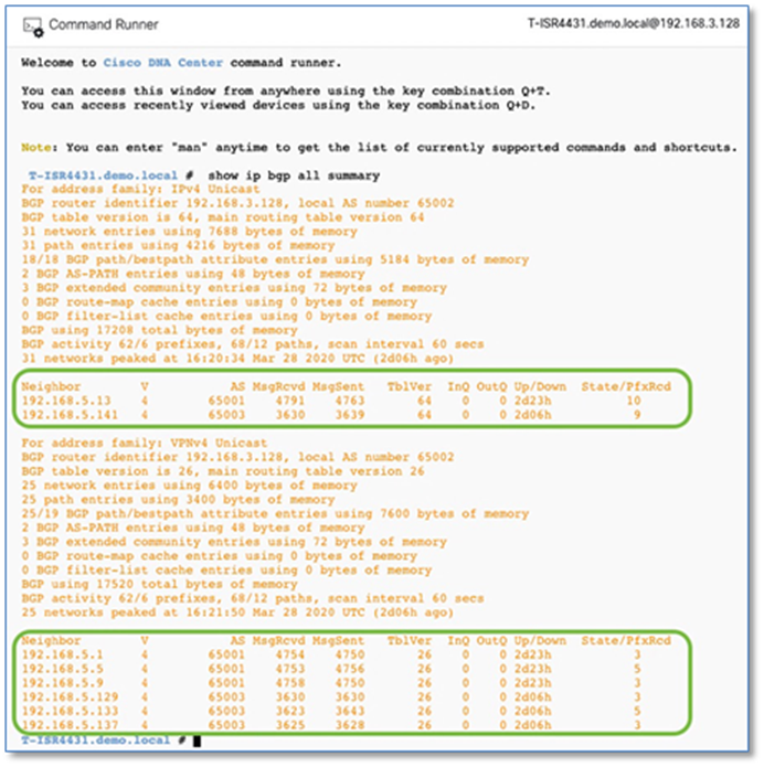
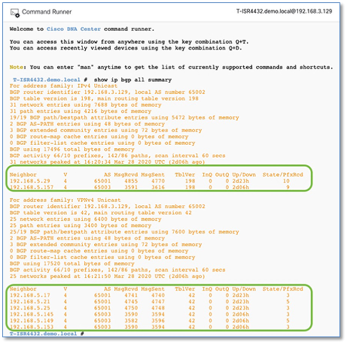
Procedure 5. Redistribution and route leaking between VRF and global
With Shared Services routes in the GRT on the Fusion device and BGP adjacencies formed, import and export maps can be used under VRF definitions to leak routes between Global and VRFs. It’s always a good practice to attach a route-map with a match prefix-list to control the route leaking.
Step 1. Configure prefix-list matching the data center subnets and IP address pools with virtual networks.
Device: T-ISR4431 & T-ISR4432
ip prefix-list DATA-SITE-A permit 192.168.16.0/24
ip prefix-list VOICE-SITE-A permit 192.168.17.0/24
ip prefix-list WIFI-SITE-A permit 192.168.18.0/24
ip prefix-list BMS-SITE-A permit 192.168.19.0/24
ip prefix-list GUEST-SITE-A permit 192.168.20.0/24
ip prefix-list AP-SITE-A permit 192.168.21.0/24
ip prefix-list LAN_POOL-SITE-A permit 192.168.4.0/25 le 32
ip prefix-list LAN_POOL-SITE-A permit 192.168.3.0/25 le 32
ip prefix-list DATA-SITE-B permit 192.168.32.0/24
ip prefix-list VOICE-SITE-B permit 192.168.33.0/24
ip prefix-list WIFI-SITE-B permit 192.168.34.0/24
ip prefix-list BMS-SITE-B permit 192.168.35.0/24
ip prefix-list GUEST-SITE-B permit 192.168.36.0/24
ip prefix-list AP-SITE-B permit 192.168.37.0/24
ip prefix-list LAN_POOL-SITE-B permit 192.168.4.128/25 le 32
ip prefix-list LAN_POOL-SITE-A permit 192.168.3.128/25 le 32
Step 2. Configure route-maps
Device: T-ISR4431 & T-ISR4432
route-map GRT-2-FABRIC permit 10
match ip address prefix-list DC_Routes
!
route-map GUEST_VN permit 10
match ip address prefix-list GUEST-SITE-A
match ip address prefix-list GUEST-SITE-B
!
route-map BMS_VN permit 10
match ip address prefix-list BMS-SITE-A
match ip address prefix-list BMS-SITE-B
!
route-map CAMPUS_VN permit 10
match ip address prefix-list DATA-SITE-A
match ip address prefix-list VOICE-SITE-A
match ip address prefix-list WIFI-SITE-A
match ip address prefix-list DATA-SITE-B
match ip address prefix-list VOICE-SITE-B
match ip address prefix-list WIFI-SITE-B
Step 3. Configure Import and Export maps per VRF definition to perform Route Leaking from Global to VRF and Vice Versa
Device: T-ISR4431 & T-ISR4432
vrf definition CAMPUS
address-family ipv4
import ipv4 unicast map GRT-2-FABRIC
export ipv4 unicast map CAMPUS_VN
!
vrf definition BMS
address-family ipv4
import ipv4 unicast map GRT-2-FABRIC
export ipv4 unicast map BMS_VN
!
vrf definition GUEST
address-family ipv4
import ipv4 unicast map GRT-2-FABRIC
export ipv4 unicast map GUEST_VN
Step 4. Route redistribution across routing protocols
Configured in the LAN Automation workflow, ISIS is the routing protocol configured between fabric borders and fabric edges and a default route is injected from the border nodes towards fabric edges. To make the fabric control plane protocol more resilient, it's important that a specific route to the WLC is present in each fabric edge Global Routing Table. Hence the route to WLC's IP address should be either redistributed into the underlay IGP protocol at the Border or configured statically at each node. In other words, the WLC should be reachable through a specific route rather than just the default route.
Device: A-9500-32C and A-9500-32QC
ip prefix-list DC_Routes permit 192.168.1.0/24
!
route-map DC_Subnets permit 10
match ip address prefix-list DC_Routes
!
router isis
redistribute bgp 65001 route-map DC_Subnets
Device: B-9500-32QC-1 and B-9500-32QC-2
ip prefix-list DC_Routes permit 192.168.1.0/24
!
route-map DC_Subnets permit 10
match ip address prefix-list DC_Routes
!
router isis
redistribute bgp 65003 route-map DC_Subnets
Step 5. To advertise the ISIS routes which includes fabric edge loopbacks and cross connect IP address into BGP, perform the the following redistribution.
Device: A-9500-32C and A-9500-32QC
ip prefix-list LAN_POOL-SITE-A permit 192.168.4.0/25 le 32
!
route-map ISIS-2-BGP permit 10
match ip address prefix-list LAN_POOL-SITE-A
!
router bgp 65001
address-family ipv4
redistribute isis route-map ISIS-2-BGP
Device: B-9500-32QC-1 and B-9500-32QC-2
ip prefix-list LAN_POOL-SITE-B permit 192.168.4.128/25 le 32
!
route-map ISIS-2-BGP permit 10
match ip address prefix-list LAN_POOL-SITE-B
!
router bgp 65003
address-family ipv4
redistribute isis route-map ISIS-2-BGP
Step 6. To advertise the OSPF learned Data Center Routes into BGP, perform the following redistribution.
Device: T-ISR4431 & T-ISR4432
router bgp 65002
!
address-family ipv4
redistribute ospf 1 route-map GRT-2-FABRIC
Step 7. To advertise the fabric’s BGP learnt routes into OSPF, perform the following redistribution.
Device: T-ISR4431 & T-ISR4432
route-map FABRIC-2-GRT permit 10
match ip address prefix-list DATA-SITE-A
match ip address prefix-list VOICE-SITE-A
match ip address prefix-list WIFI-SITE-A
match ip address prefix-list DATA-SITE-B
match ip address prefix-list VOICE-SITE-B
match ip address prefix-list WIFI-SITE-B
!
route-map FABRIC-2-GRT permit 20
match ip address prefix-list BMS-SITE-A
match ip address prefix-list BMS-SITE-B
!
route-map FABRIC-2-GRT permit 30
match ip address prefix-list GUEST-SITE-A
match ip address prefix-list GUEST-SITE-B
!
route-map FABRIC-2-GRT permit 40
match ip address prefix-list AP-SITE-A
match ip address prefix-list AP-SITE-B
match ip address prefix-list LAN_POOL-SITE-A
match ip address prefix-list LAN_POOL-SITE-B
!
router ospf 1
redistribute bgp 65002 route-map FABRIC-2-GRT
Step 8. Verify route redistribution and route leaking
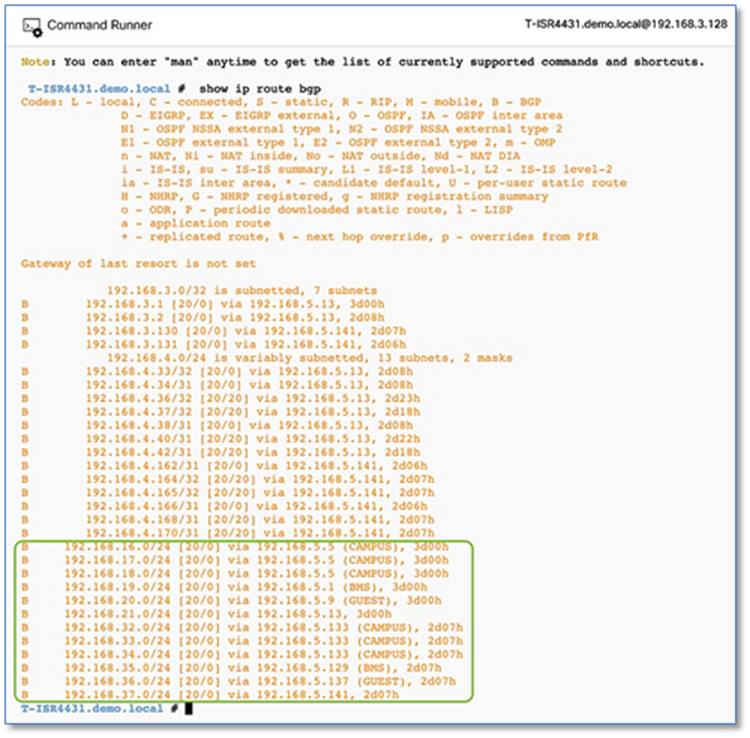
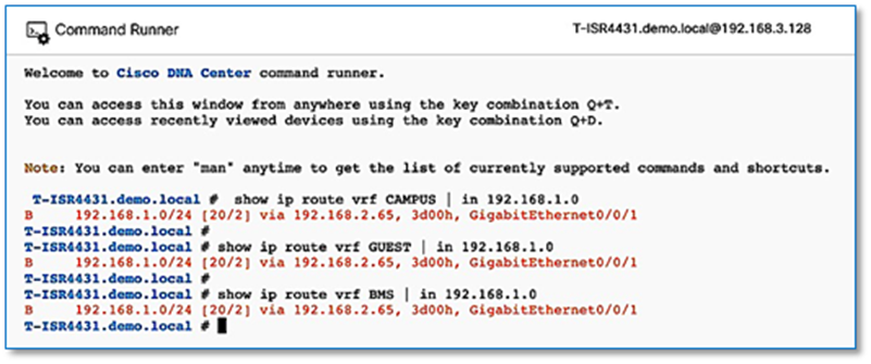
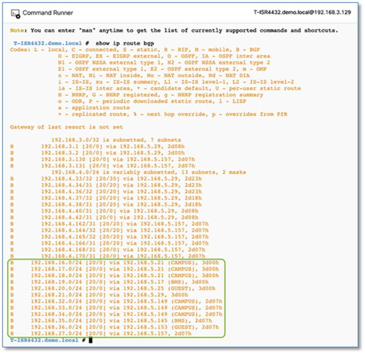
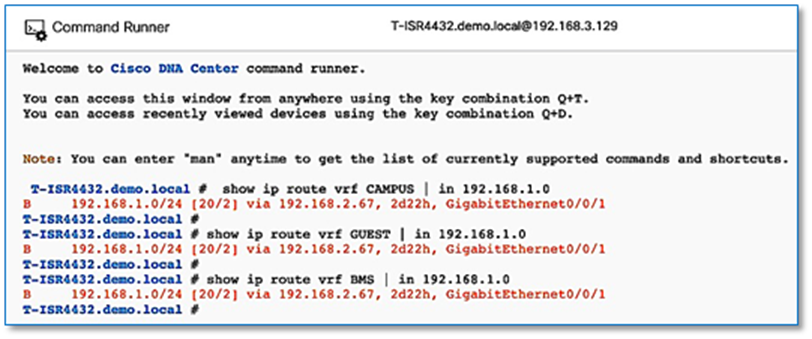
Procedure 6. Configuring iBGP adjacencies between border nodes
As discussed in the design consideration section, if there isn’t full mesh connectivity between border nodes and the fusion device, it is recommended to configure iBGP between the two borders nodes to protect against connectivity failure.
| Tech tip |
| To detect forwarding path failures faster and decrease BGP reconvergence time, enable BFD on the SVI’s and register BGP as registered protocol with BFD. Refer to Appendix section for detailed configuration. |
Step 1. Set the interface between two border nodes to default.
Device: A-9500-32C
default interface HundredGigE1/0/7
Device: A-9500-32QC
default interface FortyGigabitEthernet1/0/7
Device: B-9500-32QC-1 and B-9500-32QC-2
Default interface FortyGigabitEthernet1/0/2
Step 2. Define VLAN numbers and configure SVIs.
Device: A-9500-32C
vlan 3101
name 3101
!
vlan 3102
name 3102
!
vlan 3103
name 3103
!
vlan 3104
name 3104
!
interface Vlan3101
description vrf interface to Border Node
vrf forwarding BMS
ip address 192.168.2.60 255.255.255.254
no ip redirects
ip route-cache same-interface
!
interface Vlan3102
description vrf interface to Border Node
vrf forwarding CAMPUS
ip address 192.168.2.62 255.255.255.254
no ip redirects
ip route-cache same-interface
!
interface Vlan3103
description vrf interface to Border Node
vrf forwarding GUEST
ip address 192.168.2.64 255.255.255.254
no ip redirects
ip route-cache same-interface
!
interface Vlan3104
description interface to Border Node
ip address 192.168.2.66 255.255.255.254
no ip redirects
ip route-cache same-interface
!
interface HundredGigE1/0/7
description *** 40G Link to C9500-32QC Fo 1/0/7 ***
switchport mode trunk
switchport trunk allowed vlan 3101-3104
Device: A-9500-32QC
vlan 3101
name 3101
!
vlan 3102
name 3102
!
vlan 3103
name 3103
!
vlan 3104
name 3104
!
interface Vlan3101
description vrf interface to Border Node
vrf forwarding BMS
ip address 192.168.2.61 255.255.255.254
no ip redirects
ip route-cache same-interface
!
interface Vlan3102
description vrf interface to Border Node
vrf forwarding CAMPUS
ip address 192.168.2.63 255.255.255.254
no ip redirects
ip route-cache same-interface
!
interface Vlan3103
description vrf interface to Border Node
vrf forwarding GUEST
ip address 192.168.2.65 255.255.255.254
no ip redirects
ip route-cache same-interface
!
interface Vlan3104
description interface to Border Node
ip address 192.168.2.67 255.255.255.254
no ip redirects
ip route-cache same-interface
!
interface FortyGigabitEthernet1/0/7
description *** 40G Link to A9500-32C Hu1/0/7 ***
switchport mode trunk
switchport trunk allowed vlan 3101-3104
Device: B-9500-32QC-1
vlan 3109
name 3109
!
vlan 3110
name 3110
!
vlan 3111
name 3111
!
vlan 3112
name 3112
interface Vlan3109
description vrf interface to Border Node
vrf forwarding BMS
ip address 192.168.2.148 255.255.255.254
no ip redirects
ip route-cache same-interface
!
interface Vlan3110
description vrf interface to Border Node
vrf forwarding CAMPUS
ip address 192.168.2.150 255.255.255.254
no ip redirects
ip route-cache same-interface
!
interface Vlan3111
description vrf interface to Border Node
vrf forwarding GUEST
ip address 192.168.2.152 255.255.255.254
no ip redirects
ip route-cache same-interface
!
interface Vlan3112
description interface to Border Node
ip address 192.168.2.154 255.255.255.254
no ip redirects
ip route-cache same-interface
!
interface FortyGigabitEthernet1/0/2
description *** 40G Link to B-9500-32QC-2 Fo 1/0/2 ***
switchport mode trunk
switchport trunk allowed vlan 3109-3112
Device: B-9500-32QC-2
vlan 3109
name 3109
!
vlan 3110
name 3110
!
vlan 3111
name 3111
!
vlan 3112
name 3112
!
interface Vlan3109
description vrf interface to Border Node
vrf forwarding BMS
ip address 192.168.2.149 255.255.255.254
no ip redirects
ip route-cache same-interface
!
interface Vlan3110
description vrf interface to Border Node
vrf forwarding CAMPUS
ip address 192.168.2.151 255.255.255.254
no ip redirects
ip route-cache same-interface
!
interface Vlan3111
description vrf interface to Border Node
vrf forwarding GUEST
ip address 192.168.2.153 255.255.255.254
no ip redirects
ip route-cache same-interface
!
interface Vlan3112
description interface to Border Node
ip address 192.168.2.155 255.255.255.254
no ip redirects
ip route-cache same-interface
!
interface FortyGigabitEthernet1/0/2
description *** 40G Link to B-9500-32QC-1 Fo 1/0/2 ***
switchport mode trunk
switchport trunk allowed vlan 3109-3112
Step 3. Enable iBGP between border nodes and use VLAN IDs as the update source
Device: A-9500-32C
router bgp 65001
neighbor 192.168.2.67 remote-as 65001
neighbor 192.168.2.67 update-source Vlan3104
!
address-family ipv4
neighbor 192.168.2.67 activate
exit-address-family
!
address-family ipv4 vrf BMS
neighbor 192.168.2.61 remote-as 65001
neighbor 192.168.2.61 update-source Vlan3101
neighbor 192.168.2.61 activate
exit-address-family
!
address-family ipv4 vrf CAMPUS
neighbor 192.168.2.63 remote-as 65001
neighbor 192.168.2.63 update-source Vlan3102
neighbor 192.168.2.63 activate
exit-address-family
!
address-family ipv4 vrf GUEST
neighbor 192.168.2.65 remote-as 65001
neighbor 192.168.2.65 update-source Vlan3103
neighbor 192.168.2.65 activate
exit-address-family
Device: A-9500-32QC
router bgp 65001
neighbor 192.168.2.66 remote-as 65001
neighbor 192.168.2.66 update-source Vlan3104
!
address-family ipv4
neighbor 192.168.2.66 activate
exit-address-family
!
address-family ipv4 vrf BMS
neighbor 192.168.2.60 remote-as 65001
neighbor 192.168.2.60 update-source Vlan3101
neighbor 192.168.2.60 activate
exit-address-family
!
address-family ipv4 vrf CAMPUS
neighbor 192.168.2.62 remote-as 65001
neighbor 192.168.2.62 update-source Vlan3102
neighbor 192.168.2.62 activate
exit-address-family
!
address-family ipv4 vrf GUEST
neighbor 192.168.2.64 remote-as 65001
neighbor 192.168.2.64 update-source Vlan3103
neighbor 192.168.2.64 activate
exit-address-family
Device: B-9500-32QC-1
router bgp 65003
neighbor 192.168.2.155 remote-as 65003
neighbor 192.168.2.155 update-source Vlan3112
!
address-family ipv4
neighbor 192.168.2.155 activate
exit-address-family
!
address-family ipv4 vrf BMS
neighbor 192.168.2.149 remote-as 65003
neighbor 192.168.2.149 update-source Vlan3109
neighbor 192.168.2.149 activate
exit-address-family
!
address-family ipv4 vrf CAMPUS
neighbor 192.168.2.151 remote-as 65003
neighbor 192.168.2.151 update-source Vlan3110
neighbor 192.168.2.151 activate
exit-address-family
!
address-family ipv4 vrf GUEST
neighbor 192.168.2.153 remote-as 65003
neighbor 192.168.2.153 update-source Vlan3111
neighbor 192.168.2.153 activate
exit-address-family
Device: B-9500-32QC-2
router bgp 65003
neighbor 192.168.2.154 remote-as 65003
neighbor 192.168.2.154 update-source Vlan3112
!
address-family ipv4
neighbor 192.168.2.154 activate
exit-address-family
!
address-family ipv4 vrf BMS
neighbor 192.168.2.148 remote-as 65003
neighbor 192.168.2.148 update-source Vlan3109
neighbor 192.168.2.148 activate
exit-address-family
!
address-family ipv4 vrf CAMPUS
neighbor 192.168.2.150 remote-as 65003
neighbor 192.168.2.150 update-source Vlan3110
neighbor 192.168.2.150 activate
exit-address-family
!
address-family ipv4 vrf GUEST
neighbor 192.168.2.152 remote-as 65003
neighbor 192.168.2.152 update-source Vlan3111
neighbor 192.168.2.152 activate
exit-address-family
Step 4. Disable OSPF between Fusion and Border Node.
The temporary OSPF adjacency which was established in Procedure 8 – Step 4a between Fusion and Border can be removed at this stage as we have an active BGP adjacency and BGP routes are preferred over OSPF due to administrative distance.
Device: A-9500-32C
router ospf 1
no network 192.168.5.12 0.0.0.3 area 0
Device: A-ISR4431
router ospf 1
no network 192.168.5.12 0.0.0.3 area 0
Step 5. Resync border & fusion devices. From the Cisco DNA Center, navigate to Provision > Inventory > Actions > Inventory and click Resync Device. This allows Cisco DNA Center to export configurations to update device inventory.
Step 6. Verify the iBGP adjaceny between border nodes at SITE-A and SITE-B
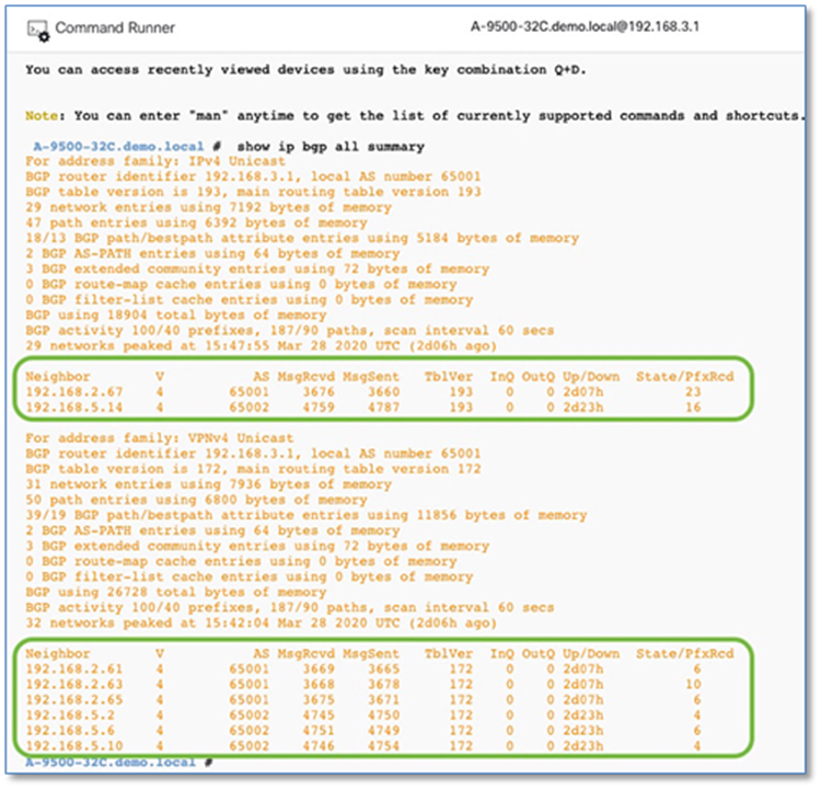
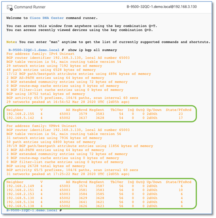
Process 10: Provisioning Access Points
Now that the Host Onboarding of the access point on the fabric edge has been completed and the required route leaking of shared services is complete, access points can now get an IP address from the DHCP Server which includes vendor-specific DHCP option 43 to join a specific WLC.
Once the APs are registered to the WLC, they will appear on the Cisco DNAC inventory page. APs must be provisioned to receive the correct RF profile configuration and to join the overlay network in the SD-Access wireless access point role. The following steps will provision the access points to floors in a building (site) and provision them with an RF profile, allowing them to operate in the fabric role.
Procedure 1. SITE-A AP provisioning
Provisioning an access point is similar to provisioning a network device.
Please refer to the Provisioning and Verifying Access Points procedure on for detailed steps on provisioning Access Points.
Cisco SD-Access Distributed Campus Prescriptive Deployment Guide
Below is the summary for review at the end of provisioning workflow with selected device location and other parameters left at its default.
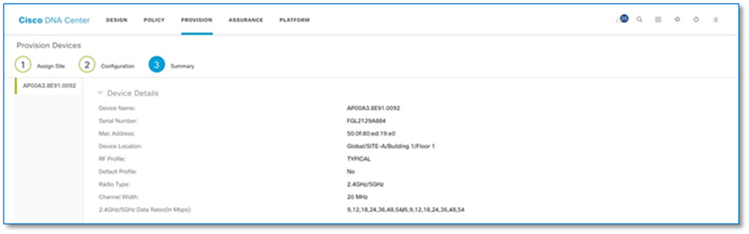
As part of the AP provisioning, the AP is configured with policy and site tags for the fabric on the C9800 Wireless LAN Controller.
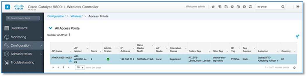
Procedure 2. SITE-B AP provisioning
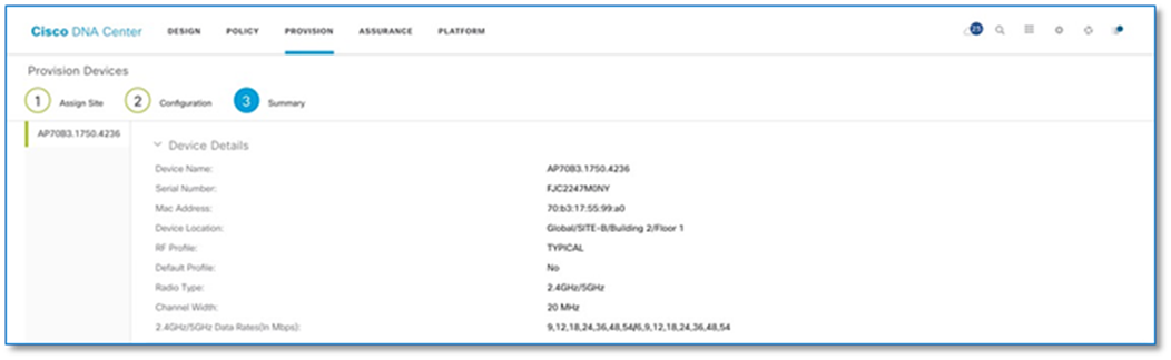
As part of AP the provisioning, the AP group config gets pushed to the WLC with the name of the site it was mapped to.
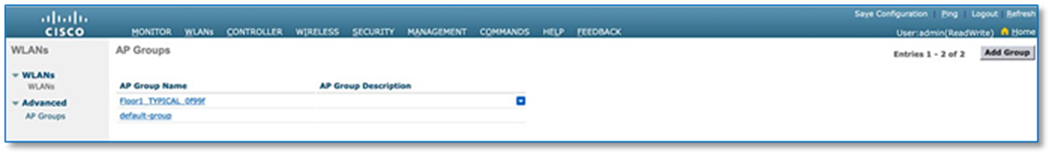
Procedure 3. Access Point Verification
Using either the device Command Runner Tool or the Global Command Runner Tool (Tools>Command Runner) you can validate the Access Tunnel status between the AP and Fabric Edge. Use show access-tunnel summary command on the respective Fabric Edge validate the tunnel status. Refer to Figure 63 below.
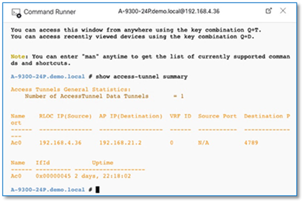
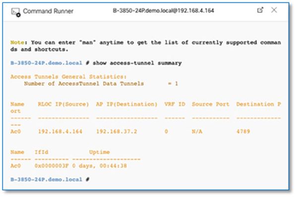
Procedure 1. Verify end to end connectivity
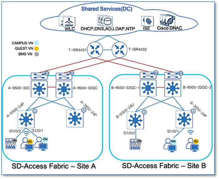
1. Endpoints with Dot1x authentication are preconfigured to use windows credentials for Dot1x authentication.
2. ISE is integrated with Active Directory to validate employee credentials for Dot1x and MAB endpoints. Endpoint MAC address are pre-added into ISE database.
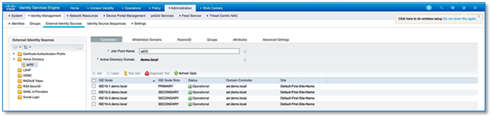
3. Authentication, Authorization polices including policy-sets are preconfigured on Cisco ISE as shown below
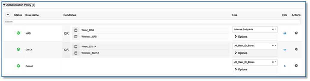
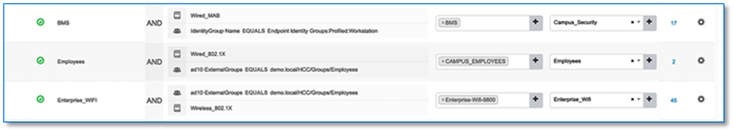
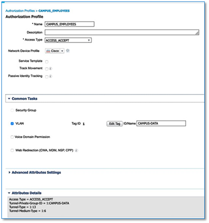
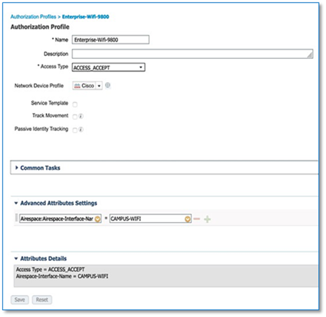
| Tech tip |
| ID/Name Tag in Figure 69 and 70 needs to match the Authentication policy field name as in Process 8 Procedure 2 Step 8 |
4. The following table highlights the endpoint to VN mapping on fabric nodes.
| VIRTUAL NETWORK |
IP POOL |
VLAN |
SUBNET |
SWITCH |
INTERFACE |
AUTH METHOD |
|
|
|
|
|
|
|
|
| CAMPUS |
DATA-SITE-A |
CAMPUS-DATA |
192.168.16.0/24 |
A-9300-24P |
G1/0/1 |
DOT1X |
| CAMPUS |
DATA-SITE-B |
CAMPUS-DATA |
192.168.32.0/24 |
B-3850-24P |
G1/0/1 |
DOT1X |
| BMS |
BMS-SITE-A |
CAMPUS-BMS |
192.168.19.0/24 |
A-9300-24P |
G1/0/2 |
MAB |
| BMS |
BMS-SITE-B |
CAMPUS-BMS |
192.168.35.0/24 |
B-9300-24U |
G1/0/2 |
MAB |
| GUEST |
GUEST-SITE-A |
CAMPUS-GUEST |
192.168.20.0/24 |
A-9300-24P |
G1/0/24(AP) |
WEBAUTH |
| GUEST |
GUEST-SITE-B |
CAMPUS-GUEST |
192.168.36.0/24 |
B-3850-24P |
G1/0/23(AP) |
WEBAUTH |
Procedure 2. Verify CAMPUS VN to Shared Service Traffic Flow
1. Endpoint connected to SITE-A fabric edge (A-9300-24P) on Port G1/0/1 is requested to authenticate.
1. Endpoint enabled for dot1x authentication and are preconfigured to use windows login credentials.
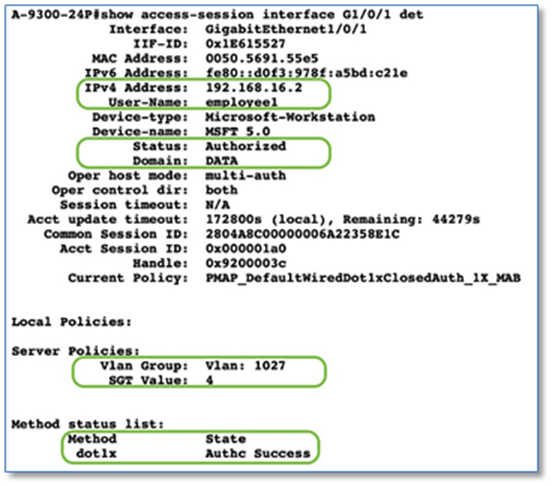
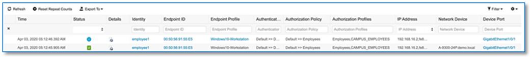
2. On the fabric edge node to display the local EID Prefix, use the LISP Database command along with mapping Instance-id.
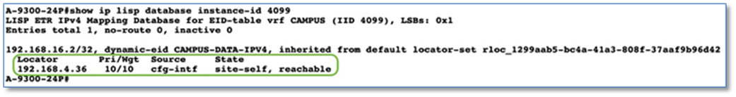
3. Verify the endpoint registration on the SITE-A primary control plane node.
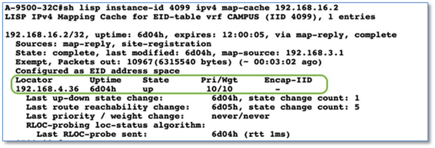
4. On the Fabric edge node, display the current LISP map cache.
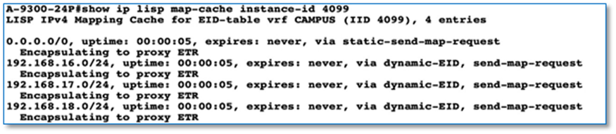
Note that there is no map-cache entry for the shared service prefix 192.168.1.0/24, and the only entry covering that prefix is the LISP default entry 0.0.0.0/0.
5. Use LIG to trigger a control plane lookup or perform a ping from the Endpoint (192.168.16.2) to Shared Service Subnet to trigger a control plane lookup
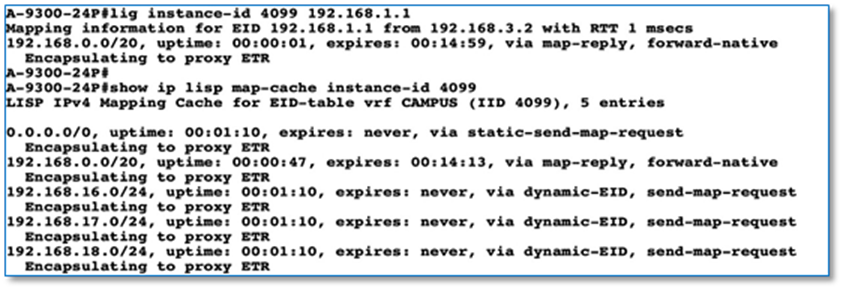
LISP computes this aggregate (192.168.0.0/20) as the largest possible block that does not contain known EID prefixes but does cover the queried address. This is due to LISP’s history as a method to solve the Default-Free Zone (DFZ) and TCAM space concerns.
Verify the Map-Cache, which now has a state of forward-native but an action of encapsulating to proxy ETR. What is the result when the packet is forwarded? To understand the forwarding decision, the LISP configuration and CEF tables must observed.
6. Verify a proxy-ETR is configured on the edge node for the instance ID 4099
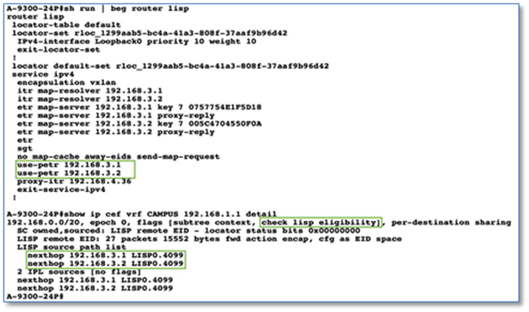
The SITE-A border nodes (192.168.3.1 and 192.168.3.2) are configured as proxy-ETR entries. This configuration is done at the default service ipv4 level under router lisp and therefore inherited by all instance IDs. With the presence of this configuration, the edge node should forward packets destined for 192.168.1.1 to the SITE-A borders based on the LISP map cache entry.
From the perspective of CEF, the Fabric Edge node will check to see if the packet meets the LISP eligibility checks. If met, the packet will be forwarded using the LISP virtual interface 4099.
7. Verify the physical forwarding path for the LISP map cache entry.
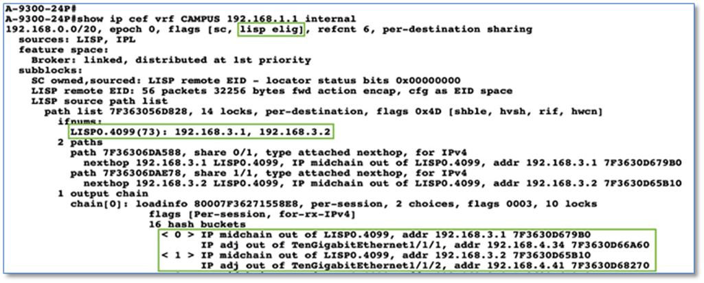
From the perspective of CEF, the edge node will encapsulate the packet as it is LISP eligible and send it from the interface LISP0.4099 with a destination of either 192.168.3.1 or 192.168.3.2. To reach either of these IP addresses, the TenGigabitEthernet 1/1/1 or 1/1/2 interface is used with a next-hop router of 192.168.4.34 or 192.168.4.41.
8. On the border node, display the current LISP map cache.
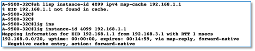
There is no map-cache entry for the desired prefix 192.168.1.1. Use lig to trigger a control plane lookup. LISP computes this aggregate (192.168.0.0/20) as the largest possible block that does not contain known EID prefixes but does cover the queried address. This is due to LISP’s history as a method to solve the DFZ and TCAM space concerns.
9. Verify the LISP map-cache on Border Node.
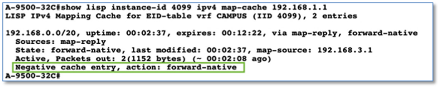
The map-cache entry with state of Negative cache entry with action as forward-native is to forward the packet using traditional routing. Let’s verify the physical forwarding path from a CEF perspective.
10. Verify the logical forwarding path for the LISP map cache entry.
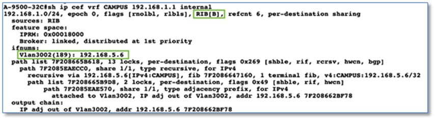
From the perspective of CEF, the SITE-A border node will use RIB and send it from the interface VLAN 3002 with a destination of 192.168.5.6. To reach 192,168.5.6 IP addresses, the Vlan 3002 interface is used with a next-hop router of 192.168.5.6 which is the border handoff link to Fusion device.
11. End to end trace route from Endpoint to Shared Service Subnet.
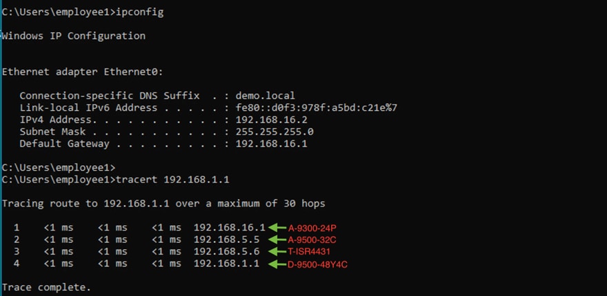
Procedure 3. Verify CAMPUS VN - SITE-A to SITE-B trafficfFlow
1. Endpoint connected to SITE-B Fabric Edge (B-3850-24P) on Port G1/0/1 is requested to authenticate.
2. Endpoint enabled for dot1x authentication and are preconfigured to use windows login credentials.
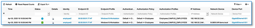
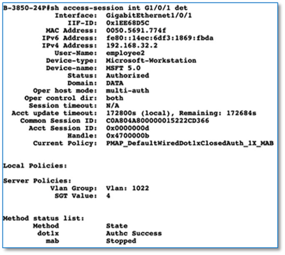
3. Verify the endpoint registration on the SITE-B primary control plane node.
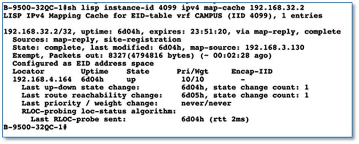
4. End to end trace route from endpoint in SITE-A to endpoint in SITE-B as part of CAMPUS VN. Due to VRF-Lite extension on fusion device, we do have end to end communication across site.
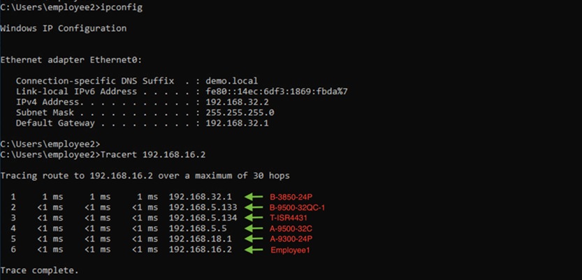
Procedure 4. Verify BMS VN - SITE-A to SITE-B traffic flow
1. Endpoint connected to SITE-A fabric edge (A-9300-24P) on port G1/0/2 to authenticate via MAB.
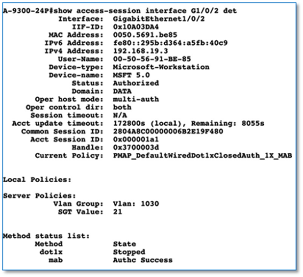
2. Endpoint connected to SITE-B fabric edge (B-9300-24U) on port G1/0/2 to authenticate via MAB.
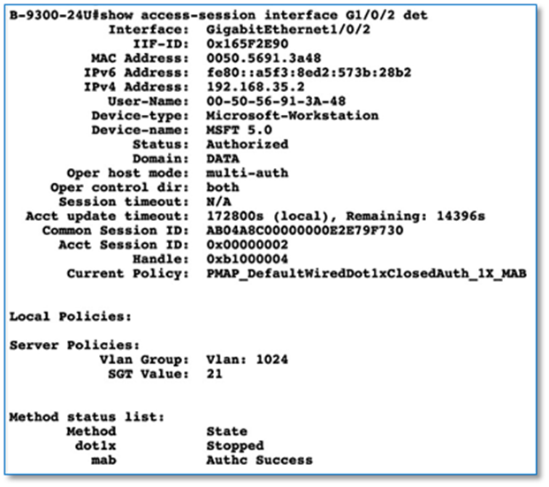
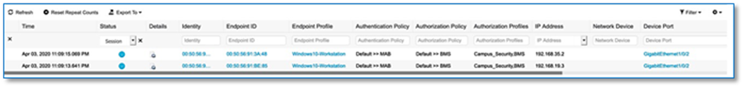
3. Perform Trace to verify reachability to shared services from BMS endpoints in SITE-A and SITE-B
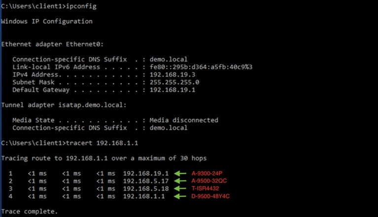
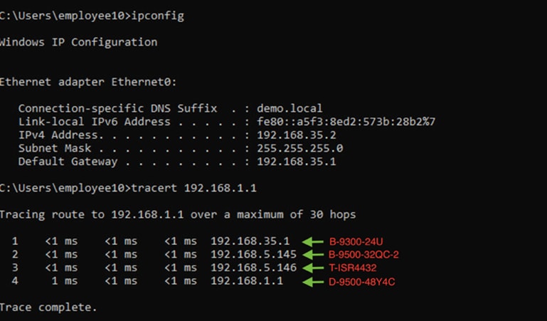
4. End to end trace route from endpoint in SITE-A to endpoint in SITE-B as part of BMS VN. Due to VRF-Lite extension on fusion device, we do have end to end communications across site.
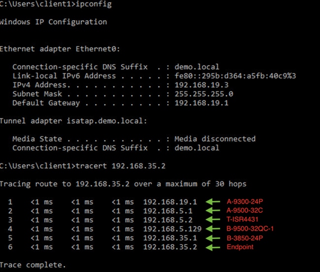
5. Verify reachability from BMS Endpoint in SITE-A to CAMPUS Endpoint in SITE-A & SITE-B. Its expected result as there is not route leaking between BMS VN and CAMPUS VN.
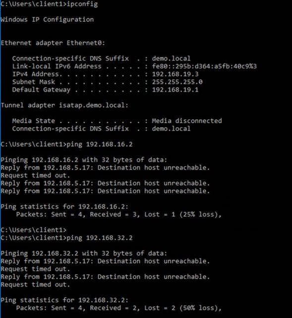
Procedure 5. Verify CAMPUS VN (SSID: Enterprise-Wifi) - Wireless Endpoint in SITE-A and SITE-B traffic flow
1. Wireless endpoint connected to
● SITE-A - Fabric edge (A-9300-24P) via AP2802 on port G1/0/24
● SITE-B – Fabric edge(B-3850-24P) via AP3802 on port G1/0/23
2. Wireless endpoint enabled for dot1x authentication and credentials are entered when connecting to Enterprise-Wifi SSID.
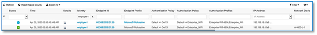

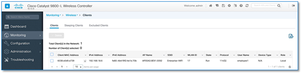
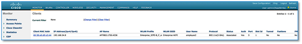
3. Perform trace tov reachability to shared services. WIFI endpoint at SITE-B and CAMPUS-DATA employee endpoint at SITE-B.
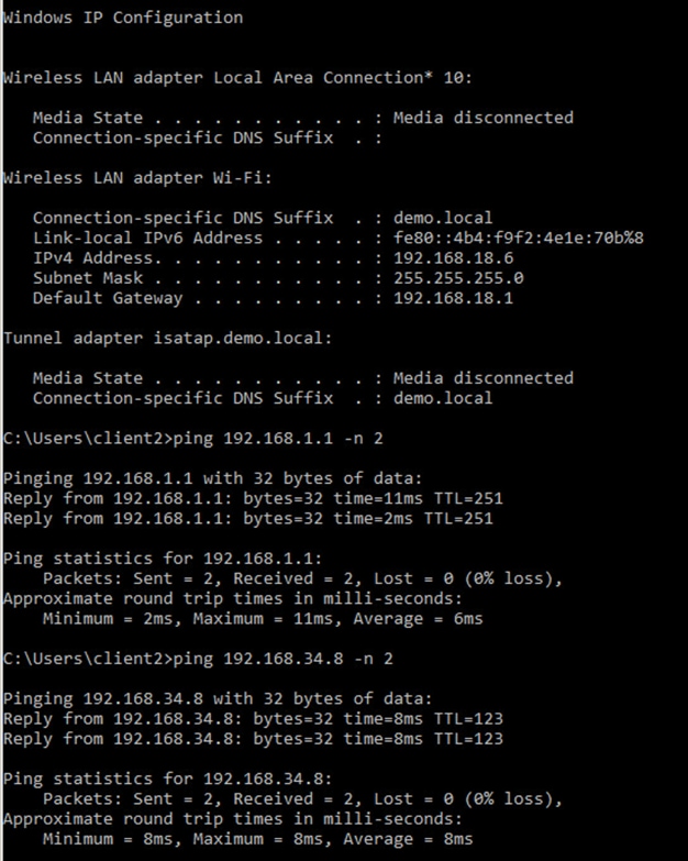
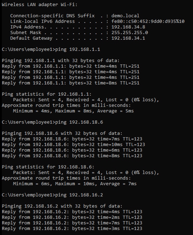
4. Perform trace to verify reachability to an endpoint in the BMS VN (SITE-A & SITE-B) from a wireless endpoint in Enterprise-WiFi.
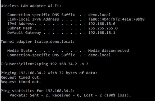
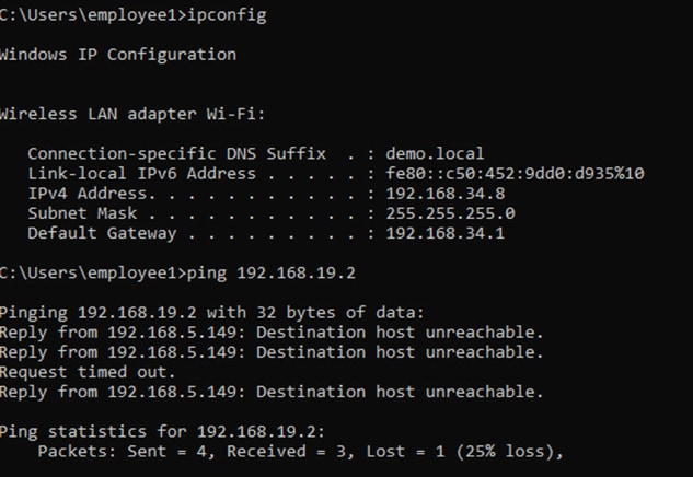
These are the expected result as there is no route leaking between BMS VN and CAMPUS VN
Procedure 6. Verify GUEST VN (SSID: GUEST-WIFI) - Wireless endpoints at SITE-A and SITE-B traffic flow
1. Wireless endpoint connected
● SITE-A - Fabric edge (A-9300-24P) via AP2802 on port G1/0/24
● SITE-B – Fabric edge(B-3850-24P) via AP3802 on port G1/0/23
2. Wireless endpoint enabled for Central WebAuth authentication when connecting to GUEST-WIFI SSID.
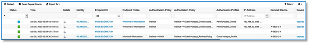
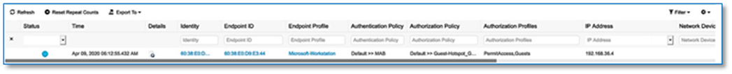
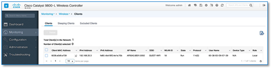
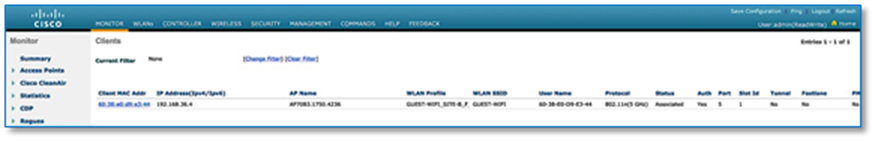
3. Perform trace to verify reachability to shared services from Guest WIFI endpoint at Site A and Site B.
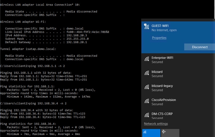
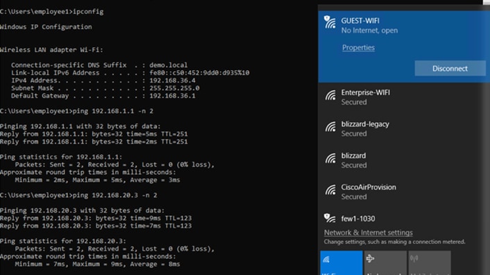
4. Perform trace to verify reachability to endpoint part of CAMPUS VN & BMS VN (SITE-A & SITE-B) from wireless endpoint part of GUEST-WIFI.
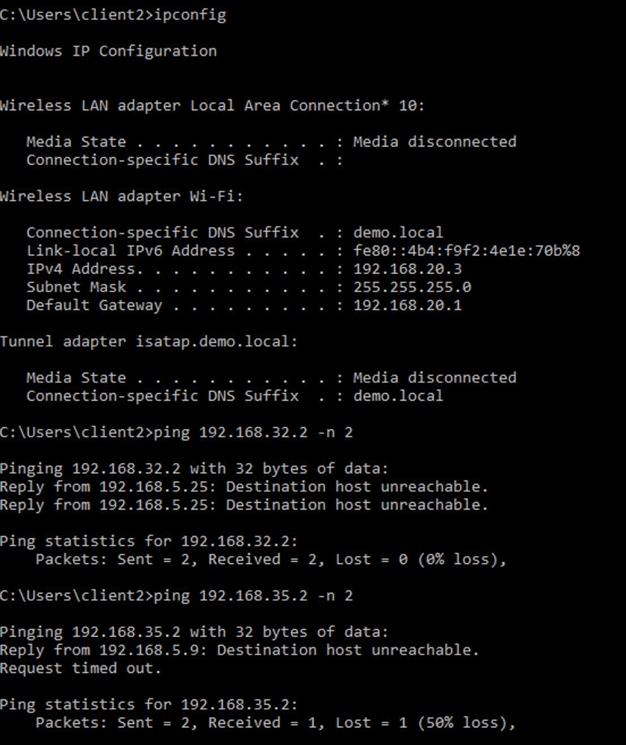
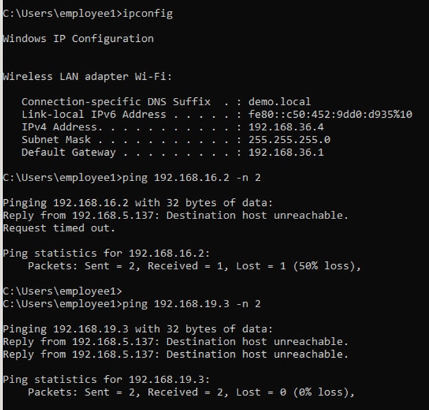
These are the expected results as there is no route leaking between GUEST VN and CAMPUS/BMS VN.
Appendix 1. Hardware and Software Code Versions
| PLATFORM |
MODEL |
SOFTWARE VERSION |
| Cisco DNA Center |
DN1-HW-APL |
Cisco DNA Center 1.3.3.1 |
| Cisco Identity Services Engine |
ISE-VM-K9 |
ISE 2.6.0.156 Patch 3 |
| Catalyst 3850 |
WS-C3850-24P-E |
16.12.1s |
| Catalyst 9300 |
C9300-24P |
16.12.2t |
| Catalyst 9500 |
C9500-32C C9500-32QC |
16.12.2t |
| ISR 4431 |
ISR4431/K9 |
16.12.2t |
| WLC 3504 Series |
AIR-CT3504-K9 |
8.10.112.0 |
| WLC 9800 |
C9800-L-C-K9 |
16.12.2t |
Appendix 2. Preparing the Underlay Network
Do not add below configuration to any devices that you intend to discover and configure using LAN Automation. Devices with existing configurations cannot be configured using LAN Automation. This example shows a configuration using Cisco IOS XE on a Cisco Catalyst switch.
Step 1. Use the device CLI to configure the hostname to make it easy to identify the device.
hostname [hostname]
Step 2. Configure local login and password
username [username] privilege 15 secret [user_password]
enable secret [enable_password]
service password-encryption
Step 3. Configure the switch to support Ethernet jumbo frames. The MTU chosen allows for the extra fabric headers and compatibility with the highest common value across most switches, and the round number should be easy to remember when configuring and troubleshooting.
system mtu 9100
Step 4. Enable Simple Network Management Protocol (SNMP) and configure SNMPv2c with both a read-only and a read-write community string, which match the credentials input into Cisco DNA Center.
snmp-server community [snmp_read_string] RO
snmp-server community [snmp_write_string] RW
Step 5. Configure the switch loopback address. For maximum resiliency and bandwidth, use a loopback interface on each device and enable Layer 3 connectivity for Cisco DNA Center in-band discovery and management.
interface Loopback0
ip address 192.168.3.XX 255.255.255.252
Step 6. Configure the switch connections within the underlay network infrastructure. Repeat this step for every link to a neighbor switch within the fabric underlay.
interface TenGigabitEthernet1/1/1
no switchport
ip address 192.168.2.XX 255.255.255.252
ip ospf network point-to-point
logging event link-status
bfd interval 100 min_rx 100 multiplier 3
no bfd echo
Step 7. Enable IP routing and enable the OSPF routing protocol on the switch/router.
! ip routing is not enabled by default for many switches
ip routing
!
router ospf 1
router-id 192.168.3.X
network 192.168.2.0 0.0.0.127 area 0
network 192.168.3.X 0.0.0.0 area 0
bfd all-interfaces
Step 8. Configure line vty for CLI management access. It is always recommended to use SSHv2 for secure connectivity to device.
line vty 0 4
login local
transport input all
transport preferred none
Procedure 1. Configure high availability (HA) stateful switch-over (SSO) on C9800-L Controllers (SITE-A)
Catalyst 9800 Series WLCs support the ability to be configured in an active/standby high availability (HA) stateful switch-over (SSO) pair. Cisco DNA Center supports the ability to take two controllers of the same model, running the same OS version, and configure them into an HA SSO pair.
Follow these steps to configure C9800-L Controllers as an HA SSO pair
Step 1. Navigate to Provision > Devices > Inventory from the Cisco DNA Center home page.
Step 2. Select device type as WLC to filter all Wireless Lan Controllers part of Inventory.
Step 3. Locate and check the box next to the Catalyst 9800-L WLC which will be the primary of the HA SSO WLC pair. For this design and deployment guide A-9800-L-1 was selected as the primary WLC.
Step 4. From the drop-down menu under Actions, select Provision > Configure WLC HA. This will bring up the High Availability side panel as shown.
Step 5. Enter the Redundancy Management IP and Peer Redundancy Management IP addresses and netmask in the respective fields and click Configure HA .
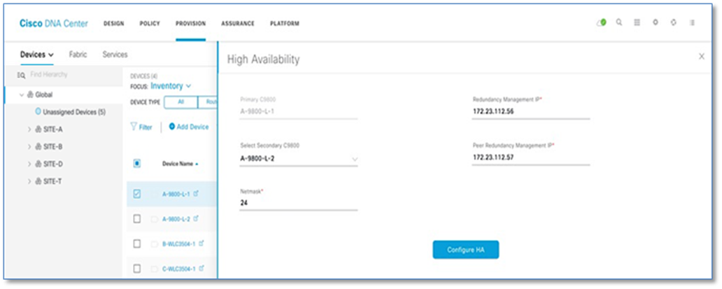
Step 6. Click OK to accept and WLCs will reload.
Step 7. After the HA is initiated, the Redundancy Summary appears. Select Primary Controller > Action > Provision > Configure WLC HA tab displays the Sync Status as HA Pairing is in Progress. When Cisco DNA Center finds that the HA pairing is successful, the Sync Status becomes Complete. This is triggered by the inventory poller or by manual resynchronization. By now, the secondary controller (Catalyst 9800 Series Wireless Controller 2) is deleted from Cisco DNA Center. This flow indicates successful HA configuration in the Catalyst 9800 Series Wireless Controller.
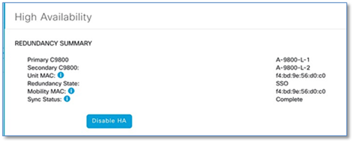
| Tech tip |
| For Catalyst 9800 Series WLCs, the redundancy management IP and peer redundancy management IP addresses which need to be configured within Cisco DNA Center are actually the redundancy port and peer redundancy port IP addresses. These are referred to as the local IP and remote IP addresses within the web UI of the Catalyst 9800 Series WLCs. The IP addresses used for redundancy management IP and peer redundancy management IP should be configured in the same subnet as the management interface of the Catalyst 9800 Series Wireless Controller. Ensure that these IP addresses are unused IP addresses within the subnet range. |
Procedure 2. Set management interface IP Address for WLC
C9800 WLCs are discovered using the SVI interface ip address, execute the following CLI on the SSO Pair to configure the SVI interface for wireless management.
Device: A-9800-L-1
wireless management interface Vlan192
Procedure 3. Adding WLC to SITE and provision network settings
Step 1. Navigate to Provision > Devices > Inventory > Select Device Type and set it to WLC from the Cisco DNA Center home page.
Step 2. Select C9800 controller (Device Name= A-9800-L-1) to provision into an SD-Access network (SITE-A).
Step 3. From the drop-down menu under Actions, select Provision > Provision Device.
Step 4. Click on the Choose a Site button in the middle of the screen
Step 5. In Choose a Site window, select Global/SITE-A/Building 1 to associate the WLC to SITE-A, Building 1
Step 6. Click the Save button
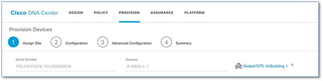
Step 7. Click Next to move to the Configuration tab under Provision Devices.
Step 8. With Active Main WLC radio button checked, click Select Primary Managed AP Location and select SITE-A/Building 1 which is the parent site, so all the children (Floors) under the parent site are also selected. Click Next.
Step 9. Review and leave the advanced configuration as is and click Next.
Step 10. On the Summary window, review the following configurations:
● Device Details
● Network Setting
● SSID
● Managed Sites
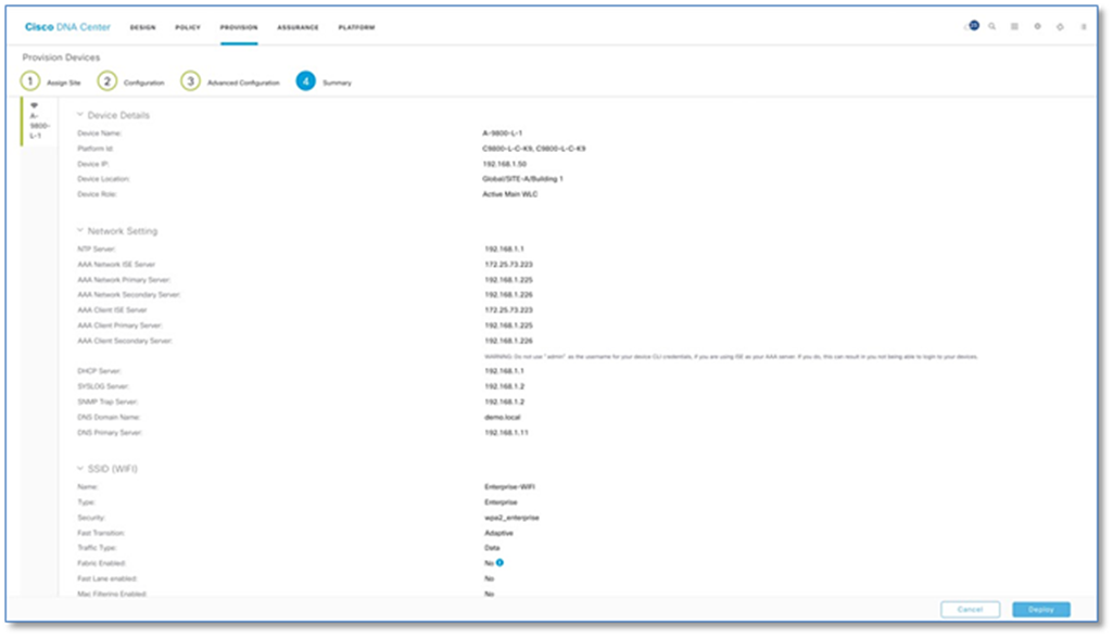
Step 11. Click Deploy to provision the Catalyst 9800 series Wireless Controller.
Step 12. To deploy the device immediately, click the Now radio button and click Apply.
Procedure 4. Verify WLAN push to Wireless LAN Controller
Verify configurations that are pushed from the Cisco DNA Center to the Catalyst 9800 Series Wireless Lan Controller. The new WLAN should be in a disabled state, because there is no IP Pool association.
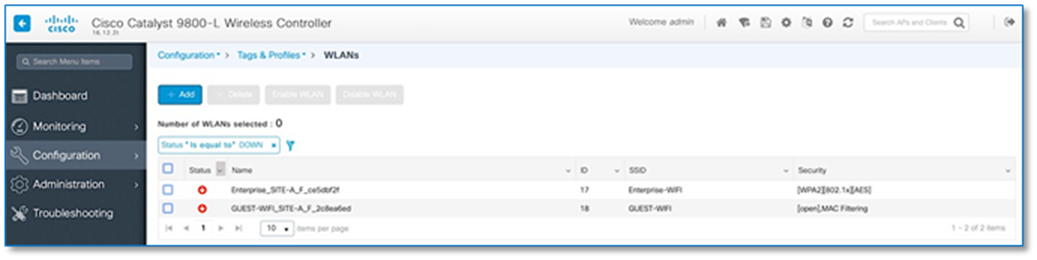
Procedure 5. Provision Site-B WLC
Repeat the Steps in Procedure 3 to provision the Cisco 3504 Series Wireless LAN Controller for SITE-B. Refer to the following figures for provision status.
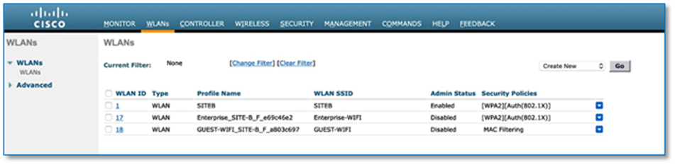
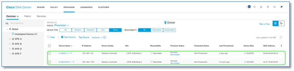
Appendix 4. Bidirectional Forwarding Detection (BFD) for fast failure detection
Device: A-9500-32C
interface range Vlan3001-3004
bfd interval 100 min_rx 100 multiplier 3
no bfd echo
!
interface range Vlan3101-3104
bfd interval 100 min_rx 100 multiplier 3
no bfd echo
!
router bgp 65001
neighbor 192.168.5.14 fall-over bfd
neighbor 192.168.2.67 fall-over bfd
!
address-family ipv4 vrf BMS
neighbor 192.168.5.2 fall-over bfd
neighbor 192.168.2.61 fall-over bfd
!
address-family ipv4 vrf CAMPUS
neighbor 192.168.5.6 fall-over bfd
neighbor 192.168.2.63 fall-over bfd
!
address-family ipv4 vrf GUEST
neighbor 192.168.5.10 fall-over bfd
neighbor 192.168.2.65 fall-over bfd
Device: A-9500-32QC
interface range Vlan3005-3008
bfd interval 100 min_rx 100 multiplier 3
no bfd echo
!
interface range Vlan3101-3104
bfd interval 100 min_rx 100 multiplier 3
no bfd echo
!
router bgp 65001
neighbor 192.168.2.66 fall-over bfd
neighbor 192.168.5.30 fall-over bfd
!
address-family ipv4 vrf BMS
neighbor 192.168.2.60 fall-over bfd
neighbor 192.168.5.18 fall-over bfd
!
address-family ipv4 vrf CAMPUS
neighbor 192.168.2.62 fall-over bfd
neighbor 192.168.5.22 fall-over bfd
!
address-family ipv4 vrf GUEST
neighbor 192.168.2.64 fall-over bfd
neighbor 192.168.5.26 fall-over bfd
Device: B-9500-32QC-1
interface range Vlan3009-3012
bfd interval 100 min_rx 100 multiplier 3
no bfd echo
interface range Vlan3109-3112
bfd interval 100 min_rx 100 multiplier 3
no bfd echo
!
router bgp 65003
neighbor 192.168.2.155 fall-over bfd
neighbor 192.168.5.142 fall-over bfd
!
address-family ipv4 vrf BMS
neighbor 192.168.2.149 fall-over bfd
neighbor 192.168.5.130 fall-over bfd
!
address-family ipv4 vrf CAMPUS
neighbor 192.168.2.151 fall-over bfd
neighbor 192.168.5.134 fall-over bfd
!
address-family ipv4 vrf GUEST
neighbor 192.168.2.153 fall-over bfd
neighbor 192.168.5.138 fall-over bfd
Device: B-9500-32QC-2
interface range Vlan3013-3016
bfd interval 100 min_rx 100 multiplier 3
no bfd echo
!
interface range Vlan3109-3112
bfd interval 100 min_rx 100 multiplier 3
no bfd echo
!
router bgp 65003
neighbor 192.168.2.154 fall-over bfd
neighbor 192.168.5.158 fall-over bfd
!
address-family ipv4 vrf BMS
neighbor 192.168.2.148 fall-over bfd
neighbor 192.168.5.146 fall-over bfd
!
address-family ipv4 vrf CAMPUS
neighbor 192.168.2.150 fall-over bfd
neighbor 192.168.5.150 fall-over bfd
!
address-family ipv4 vrf GUEST
neighbor 192.168.2.152 fall-over bfd
neighbor 192.168.5.154 fall-over bfd
Device: T-ISR4431
interface range GigabitEthernet0/0/3.3001 - GigabitEthernet0/0/3.3004
bfd interval 100 min_rx 100 multiplier 3
no bfd echo
!
interface range GigabitEthernet0/0/2.3009 - GigabitEthernet0/0/2.3012
bfd interval 100 min_rx 100 multiplier 3
no bfd echo
!
router bgp 65002
neighbor 192.168.5.13 fall-over bfd
neighbor 192.168.5.141 fall-over bfd
!
address-family ipv4 vrf BMS
neighbor 192.168.5.1 fall-over bfd
neighbor 192.168.5.129 fall-over bfd
!
address-family ipv4 vrf CAMPUS
neighbor 192.168.5.5 fall-over bfd
neighbor 192.168.5.133 fall-over bfd
!
address-family ipv4 vrf GUEST
neighbor 192.168.5.9 fall-over bfd
neighbor 192.168.5.137 fall-over bfd
Device: T-ISR4432
interface range GigabitEthernet0/0/3.3005 - GigabitEthernet0/0/3.3008
bfd interval 100 min_rx 100 multiplier 3
no bfd echo
!
interface range GigabitEthernet0/0/2.3013 - GigabitEthernet0/0/2.3016
bfd interval 100 min_rx 100 multiplier 3
no bfd echo
!
router bgp 65002
neighbor 192.168.5.29 fall-over bfd
neighbor 192.168.5.157 fall-over bfd
!
address-family ipv4 vrf BMS
neighbor 192.168.5.17 fall-over bfd
neighbor 192.168.5.145 fall-over bfd
!
address-family ipv4 vrf CAMPUS
neighbor 192.168.5.21 fall-over bfd
neighbor 192.168.5.149 fall-over bfd
!
address-family ipv4 vrf GUEST
neighbor 192.168.5.25 fall-over bfd
neighbor 192.168.5.153 fall-over bfd
Recommended For You
CVD – Software-Defined Access Solution Design Guide
CVD – Software-Defined Access Deployment Guide
CVD – SD-Access Segmentation Design Guide
SD-Access Resources – Cisco Community
Cisco Identity Services Engine Installation Guide
For comments and suggestions about this guide and related guides, join the discussion on Cisco Community at https://cs.co/en-cvds.