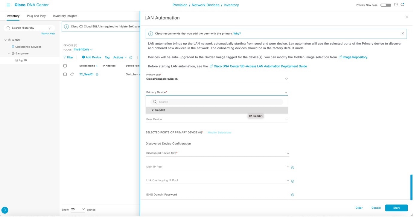
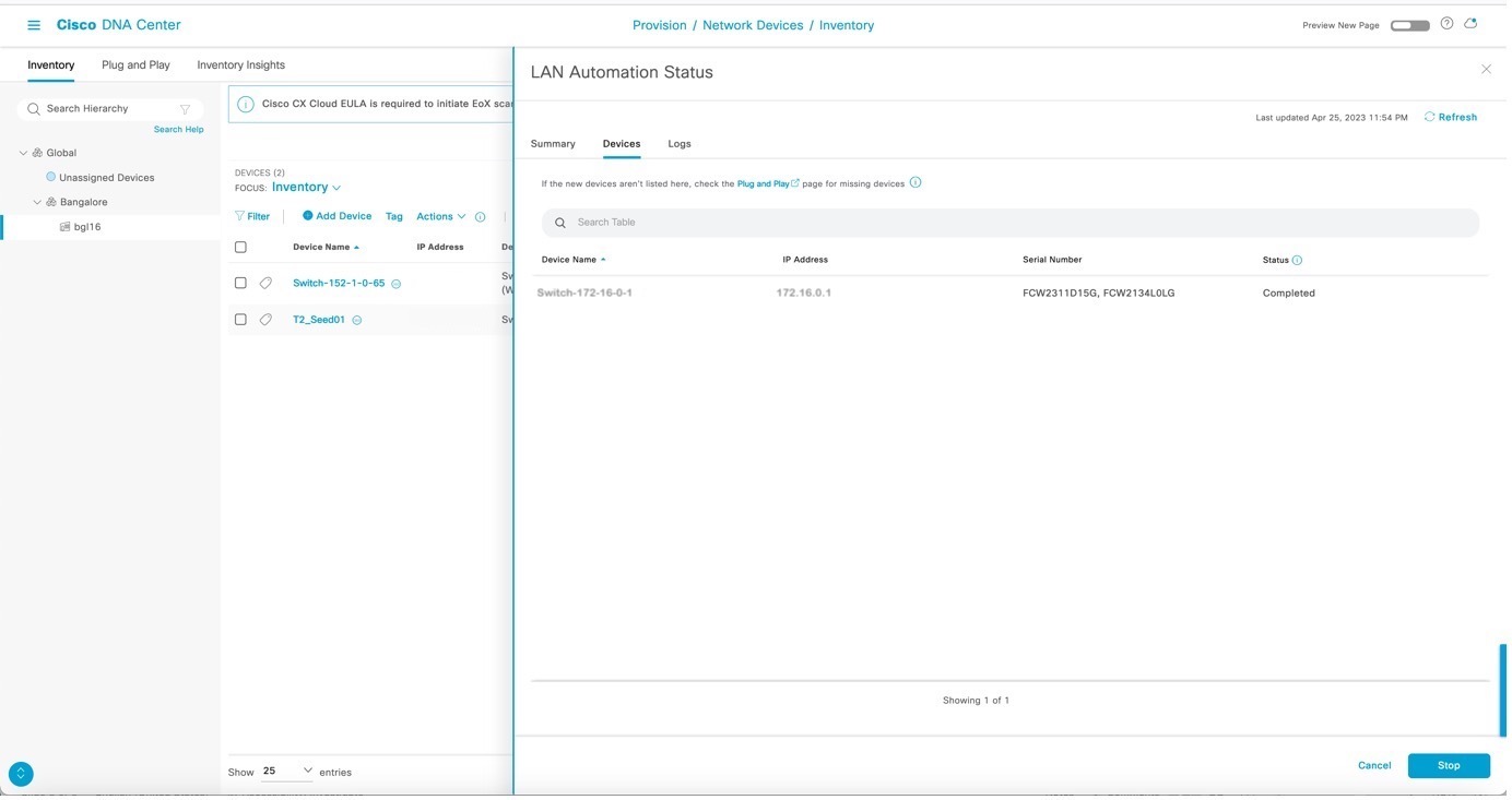
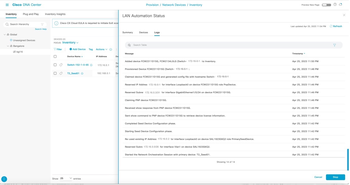
After LAN automation starts, click LAN Automation Status to monitor the progress.
Sample configuration for seed devices
After LAN automation starts, the loopback and IS-IS configuration is pushed to the seed devices.
You can refer to these commands to view device configurations:
System MTU and IP multicast routing information
show running-config | section system mtu
show running-config | section ip multicast
show running-config | section ip pim
Loopback IP and IS-IS configuration
show running-config interface Loopback0
show running-config | section router isis
DHCP pool information
show running-config | section ip dhcp
VLAN 1
sh run int vlan1
Other interface configurations
sh run int <interface_name>
This table lists sample configurations for the primary seed device.
Table 1. Primary seed configuration
Configuration type
Sample code
System MTU and IP multicast routing information
!exec: enable
!
system mtu 9100
!
ip multicast-routing
ip pim ssm default
!
Loopback IP and IS-IS configuration
If the secondary seed is configured, it also gets configured with the loopback IP and IS-IS configuration.
interface Loopback0
   ip address 10.4.210.123 255.255.255.255
   description Fabric Node Router ID
!
router isis
   net 49.0000.0100.0421.0123.00
   domain-password *
   is-type level-2-only
  metric-style wide
  nsf ietf
   log-adjacency-changes
   bfd all-interfaces
   passive-interface Loopback0
   default-information originate
!
interface Loopback0
ip router isis

clns mtu 1400

ip pim sparse-mode
exit
!
DHCP pool information
ip dhcp pool nw_orchestration_pool
  network 10.4.218.0 255.255.255.192
  option 43 ascii 5A1D;B2;K4;I10.4.249.241;J80;
  default-router 10.4.218.1
  class ciscopnp
    address range 10.4.218.2 10.4.218.62
!
ip dhcp class ciscopnp
  option 60 hex 636973636f706e70
!
ip dhcp excluded-address 10.4.218.1
!
VLAN 1 configuration
vlan 1
!
interface Vlan1
  ip address 10.4.218.1 255.255.255.192
  no shutdown
  ip router isis
  clns mtu 1400
   bfd interval 500 min_rx 500 multiplier 3
   no bfd echo
exit
!
Switch port configuration on interfaces used for discovery
Each discovery interface on the primary seed device gets this configuration.
Multicast configuration (optional; only configured if the multicast check box is checked)
If the Rendezvous Point (RP) for the underlay multicast needs to be the border, ensure to start LAN automation with multicast enabled using a switch that is planned to be the border as the seed device.
If the peer seed is configured, these multicast CLIs are pushed on the peer seed as well. The same rp-address is used to configure Loopback60000 on both the primary and peer seeds.
interface Loopback60000
  ip address 10.4.218.67 255.255.255.255
  ip pim sparse-mode
  ip router isis

ip pim register-source Loopback0
ip pim rp-address 10.4.218.67
This table lists sample configurations for the secondary seed device.
Table 2. Secondary seed configuration
Configuration type
Sample code
System configuration and IP multicast routing information
!exec: enable
!
system mtu 9100
!
ip multicast-routing
ip pim ssm default
!
Loopback IP and IS-IS configuration
interface Loopback0
  ip address 10.4.210.124 255.255.255.255
  description Fabric Node Router ID
!
router isis
   net 49.0000.0100.0421.0124.00
   domain-password *
   is-type level-2-only
   metric-style wide
   nsf ietf
   log-adjacency-changes
   bfd all-interfaces
   passive-interface Loopback0
   default-information originate
!
interface Loopback0
ip router isis
clns mtu 1400
ip pim sparse-mode
exit
!
Note
Catalyst Center Release 2.3.3 and later support is-type level-2-only as part of the IS-IS configuration.
In Catalyst Center Release 2.3.7.5 and later, the clns mtu value is configured as 1492 instead of 1400.
5.
After device discovery starts, view the logs on the PnP agent.
Note
Do not press the Enter key on the PnP agent yet.
%INIT: waited 0 seconds for NVRAM to be available

         --- System Configuration Dialog ---

Would you like to enter the initial configuration dialog? [yes/no]:

Press RETURN to get started!

*Aug  2 23:13:50.440: %SMART_LIC-5-COMM_RESTORED: Communications with the Cisco Smart Software Manager or satellite restored
*Aug  2 23:13:51.314: %CRYPTO_ENGINE-5-KEY_ADDITION: A key named TP-self-signed-1875844429 has been generated or imported
*Aug  2 23:13:51.315: %SSH-5-ENABLED: SSH 1.99 has been enabled
*Aug  2 23:13:51.355: %PKI-4-NOCONFIGAUTOSAVE: Configuration was modified.  Issue "write memory" to save new IOS PKI configuration
*Aug  2 23:13:51.418: %CRYPTO_ENGINE-5-KEY_ADDITION: A key named TP-self-signed-1875844429.server has been generated or imported
*Aug  2 23:13:52.071: %LINK-5-CHANGED: Interface GigabitEthernet0/0, changed state to administratively down
*Aug  2 23:13:53.071: %LINEPROTO-5-UPDOWN: Line protocol on Interface GigabitEthernet0/0, changed state to down
*Aug  2 23:14:00.112: %HMANRP-6-EMP_ELECTION_INFO: EMP active switch 1 elected: EMP_RELAY: Mgmt port status DOWN, reelecting EMP active switch

*Aug  2 23:14:00.112: %HMANRP-6-EMP_NO_ELECTION_INFO: Could not elect active EMP switch, setting emp active switch to 0: EMP_RELAY: Could not elect switch with mgmt port UP
*Aug  2 23:14:02.000: %SYS-6-CLOCKUPDATE: System clock has been updated from 23:14:04 UTC Thu Aug 2 2018 to 23:14:02 UTC Thu Aug 2 2018, configured from console by vty0.
Aug  2 23:14:02.000: %PKI-6-AUTHORITATIVE_CLOCK: The system clock has been set.
Aug  2 23:14:02.462: %PNP-6-PNP_DISCOVERY_DONE: PnP Discovery done successfully
Aug  2 23:14:07.847: %PKI-4-NOCONFIGAUTOSAVE: Configuration was modified.  Issue "write memory" to save new IOS PKI configuration
Aug  2 23:14:16.348: %AN-6-AN_ABORTED_BY_CONSOLE_INPUT: Autonomic disabled due to User intervention on console. configure 'autonomic' to enable it.
%Error opening tftp://255.255.255.255/network-confg (Timed out)
Aug  2 23:14:25.263: AUTOINSTALL: Tftp script execution not successful for Vl1.
6.
After the device is discovered, Catalyst Center checks if a golden image is marked for the switch family of the discovered device. If a golden image is marked and the discovered device is not running it, LAN automation first upgrades the discovered device to the golden image. If not, Catalyst Center skips the image upgrade and pushes the initial device configuration.
Sample logs for image upgrade:
Oct  5 19:20:11.437: MCP_INSTALLER_NOTICE:
Installer: Source file flash:cat9k_iosxe.16.06.04s.SPA.bin is in flash, Install directly
Oct  5 19:20:12.450: %IOSXE-5-PLATFORM: Switch 1 R0/0: Oct  5 19:20:12 provision.sh: %INSTALL-5-OPERATION_START_INFO: Started install package flash:cat9k_iosxe.16.06.04s.SPA.bin
Oct  5 19:20:22.778: %IOSXE-5-PLATFORM: Switch 1 R0/0: Oct  5 19:20:22 packtool.sh: %INSTALL-5-OPERATION_START_INFO: Started expand package flash:cat9k_iosxe.16.06.04s.SPA.bin
Oct  5 19:21:26.034: %IOSXE-5-PLATFORM: Switch 1 R0/0: Oct  5 19:21:26 packtool.sh: %INSTALL-5-OPERATION_COMPLETED_INFO: Completed expand package flash:cat9k_iosxe.16.06.04s.SPA.bin
Oct  5 19:22:09.861: %IOSXE-5-PLATFORM: Switch 1 R0/0: Oct  5 19:22:09 provision.sh: %INSTALL-5-OPERATION_COMPLETED_INFO: Completed install package flash:{<package_name>}


***
*** --- SHUTDOWN NOW ---
***

Oct  5 19:22:20.950: %SYS-5-RELOAD: Reload requested by controller. Reload Reason: Image Install.
                          Chassis 1 reloading, reason - Reload command
                                                Oct  5 19:22:30.501 FP0/0: %PMAN-5-EXITACTION: Process manager is exiting: reload fp action requested
Oct  5 19:22:

Initializing Hardware...
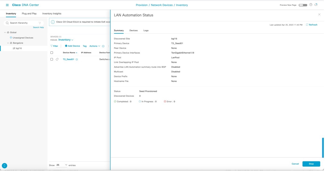
Catalyst Center pushes part of the configuration, allowing the devices to be onboarded and managed by Catalyst Center. In the LAN Automation Status window,
Status displays In Progress.
Discovered Devices displays the aggregate status of all devices being discovered.
Devices tab displays the status of individual devices being discovered.
7.
View the logs on the PnP agent, as shown in the example. It is safe to press return on the console if you want to. When you press return, the hostname changes to the value entered in the Hostname Mapping field when you started LAN automation.
Aug  2 23:14:50.682: %LINK-3-UPDOWN: Interface GigabitEthernet1/0/3, changed state to up
Aug  2 23:14:51.487: %LINK-3-UPDOWN: Interface GigabitEthernet1/0/24, changed state to up
Aug  2 23:14:51.681: %LINEPROTO-5-UPDOWN: Line protocol on Interface GigabitEthernet1/0/3, changed state to up
Aug  2 23:14:51.854: %LINK-3-UPDOWN: Interface GigabitEthernet1/0/23, changed state to up
Aug  2 23:14:52.487: %LINEPROTO-5-UPDOWN: Line protocol on Interface GigabitEthernet1/0/24, changed state to up
Aug  2 23:14:52.855: %LINEPROTO-5-UPDOWN: Line protocol on Interface GigabitEthernet1/0/23, changed state to up
000123: Aug  2 23:16:17.345: %CRYPTO_ENGINE-5-KEY_ADDITION: A key named dnac-sda has been generated or imported
000124: Aug  2 23:16:17.423: Configuring snmpv3 USM user, persisting snmpEngineBoots. Please Wait...

000125: Aug  2 23:16:17.474: %LINEPROTO-5-UPDOWN: Line protocol on Interface Loopback0, changed state to up
000126: Aug  2 23:16:17.479: %CLNS-6-DFT_OPT: Protocol timers for fast convergence are Enabled.
000128: Aug  2 23:16:17.489: %BFD-6-BFD_IF_CONFIGURE: BFD-SYSLOG: bfd config apply, idb:Vlan1
000129: Aug  2 23:16:18.423: %CLNS-3-BADPACKET: ISIS: LAN L1 hello, packet (9097) or wire (8841) length invalid from f87b.2077.b147 (Vlan1)
000130: Aug  2 23:16:18.502: %BFD-6-BFD_SESS_CREATED: BFD-SYSLOG: bfd_session_created, neigh 204.1.183.1 proc:ISIS, idb:Vlan1 handle:1 act
000131: Aug  2 23:16:19.269: %BFDFSM-6-BFD_SESS_UP: BFD-SYSLOG: BFD session ld:1 handle:1 is going UP
000132: Aug  2 23:16:19.494: %CLNS-5-ADJCHANGE: ISIS: Adjacency to 0100.1001.0001 (Vlan1) Up, new adjacency
000133: Aug  2 23:16:20.289: %PNPA-DHCP Op-43 Msg: Op43 has 5A. It is for PnP
000134: Aug  2 23:16:20.289: %PNPA-DHCP Op-43 Msg: After stripping extra characters in front of 5A, if any

000135: Aug  2 23:16:20.289: %PNPA-DHCP Op-43 Msg: _pdoon.2.ina=[Vlan1]
000136: Aug  2 23:16:20.289: %PNPA-DHCP Op-43 Msg: _papdo.2.eRr.ena
000137: Aug  2 23:16:20.289: %PNPA-DHCP Op-43 Msg: _pdoon.2.eRr.pdo=-1
000138: Aug  2 23:16:30.010: %CLNS-5-ADJCHANGE: ISIS: Adjacency to 9324-SN-BCP-1 (Vlan1) Up, new adjacency
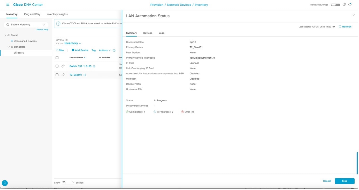
After all devices are discovered, the
Discovered Devices status changes to
Completed and the discovered devices are added to the inventory.
8.
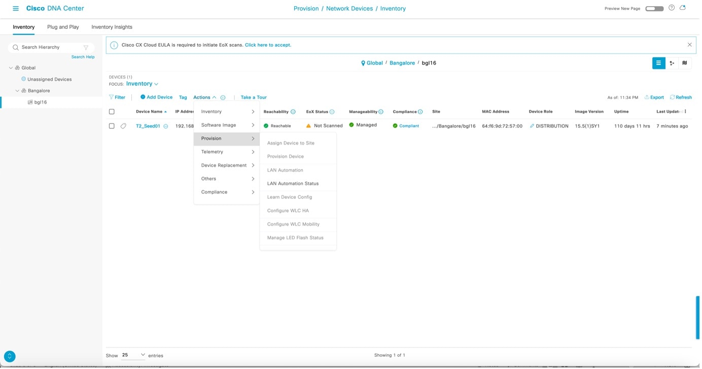
From the Catalyst Center home page, click the menu icon and chooseProvision > Inventory and filter the devices by serial number.
The newly discovered switches appear as Managed.
The example shows a sample configuration pushed to the discovered devices.
!
archive
log config
logging enable
logging size 500
hidekeys
!
!
!
service timestamps debug datetime msec
!
service timestamps log datetime msec
!
service password-encryption
!
service sequence-numbers
!
! Setup NTP Server
! Setup Timezone & Daylight Savings
!
ntp server 10.4.250.104
!
! ntp update-calendar
!
! clock timezone <timezoneName> <timezoneOffsetHours> <timezoneOffsetMinutes>
! clock summer-time <timezoneName> recurring
!
! Disable external HTTP(S) access
! Disable external Telnet access
! Enable external SSHv2 access
!
no ip http server
!
no ip http secure-server
!
ip ssh version 2
!
ip scp server enable
!
line vty 0 15
! maybe redundant
login local
transport input ssh
! maybe redundant
transport preferred none
! Set VTP mode to transparent (no auto VLAN propagation)
! Set STP mode to Rapid PVST+ (prefer for non-Fabric compatibility)
! Enable extended STP system ID
! Set Fabric Node to be STP Root for all local VLANs
! Enable STP Root Guard to prevent non-Fabric nodes from becoming Root
! Confirm whether vtp mode transparent below is needed
vtp mode transparent
!
spanning-tree mode rapid-pvst
!
spanning-tree extend system-id
! spanning-tree bridge priority 0
! spanning-tree rootguard
! spanning-tree portfast bpduguard default
no udld enable
!
errdisable recovery cause all
!
errdisable recovery interval 300
!
ip routing
!Config below applies only on underlay orchestration
!
! Setup a Loopback & IP for Underlay reachability (ID)
! Add Loopback to Underlay Routing (ISIS)
!
interface loopback 0
description Fabric Node Router ID
ip address 10.4.218.97 255.255.255.255
ip router isis
!
!
! Setup an ACL to only allow SNMP from Fabric Controller
! Enable SNMP and RW access based on ACL
!
snmp-server view DNAC-ACCESS iso in
!
snmp-server group DNACGROUPAuthPriv v3 priv read DNAC-ACCESS write DNAC-ACCESS
!
snmp-server user admin DNACGROUPAuthPriv v3 auth MD5 C1sco123 priv AES 128 C1sco123
!
!
! Set MTU to be Jumbo (9100, some do not support 9216)
!
system mtu 9100
! FABRIC UNDERLAY ROUTING CONFIG:
!
! Enable ISIS for Underlay Routing
! Specify the ISIS Network ID (e.g. encoded Loop IP)
! Specific the ISIS domain password
! Enable ISPF & FRR Load-Sharing
! Enable BFD on all (Underlay) links
!
router isis
net 49.0000.0100.0421.8097.00
domain-password <password>
is-type level-2-only
metric-style wide
nsf ietf
! fast-reroute load-sharing level-1
log-adjacency-changes
bfd all-interfaces
! passive-interface loopback 0
!
!
!
interface vlan1
bfd interval 500 min_rx 500 multiplier 3
no bfd echo
!
!
!This config goes to subtended node

username lan-admin privilege 15 password 0 C1sco123
!
enable password C1sco123
!
!
hostname CL-9300_7
!
interface vlan1
ip router isis
!
!
end
Note
Catalyst Center 2.3.3 and later support is-type level-2-only as part of the IS-IS configuration.
9.
After the Discovered Devices status changes to Completed and all discovered devices are displayed in the inventory as Managed, you can stop LAN automation.
However, before stopping LAN automation, check the Topology page to make sure that the links between the discovered device and primary and peer seed are displayed.
Choose Tools > Topology or Provision > Inventory and click the topology icon on the right.
Click the physical links between the seed and discovered device.
Make sure that the interfaces are correct. If the physical links are not visible, resynchronize the seed device where the physical links connect. After resynchronization, check the Topology window again to make sure that the links are visible before stopping LAN automation.