Information about the necessary prechecks before starting LAN automation.
Review the essential prerequisites and validation steps before you start LAN automation, such as configuring IP pools, verifying the PnP agent, managing device inventory, and checking license compliance.
IP pool subnet reachability
A LAN pool is an IP address pool that is used for IP address allocation during LAN automation. LAN automation discovery uses the LAN pool to reach PnP agents.
Before starting LAN automation, make sure that Catalyst Center can reach the IP addresses allocated from the LAN pool.
Example
For example, if the LAN pool is 192.168.10.0, Catalyst Center should have the correct route to reach this subnet.
Refer to this sample code to test IP pool reachability:
Create an SVI (VLAN 1 interface) on the primary seed device.
From the
Catalyst Center console, ping the seed device.
[On Catalyst Center CLI console]
[Sat Jun 23 05:55:18 UTC] maglev@10.195.192.157
$ ping 192.168.99.1
PING 192.168.99.1 (192.168.99.1) 56(84) bytes of data.
64 bytes from 192.168.99.1: icmp_seq=1 ttl=252 time=0.579 ms
64 bytes from 192.168.99.1: icmp_seq=2 ttl=252 time=0.684 ms
64 bytes from 192.168.99.1: icmp_seq=3 ttl=252 time=0.541 ms
Reset the SVI configuration on the seed device when finished.
[On seed device]
Switch(config)#default int vlan 1
Interface Vlan1 set to default configuration
If the ping test fails, check the route configuration on Catalyst Center.
Add a static route for LAN pool
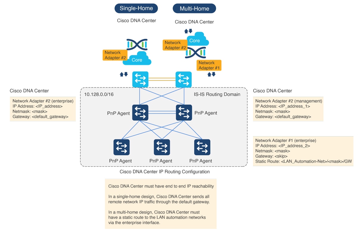
Catalyst Center hardware includes multiple physical interfaces. Each interface serves a different communication category. See the Cisco Digital Network Architecture Center Appliance Installation Guide for recommended interface connections, IP routing, and static assignment. In a single-home design, Catalyst Center performs the host function with the default gateway providing IP routing. In a multi-home design, Catalyst Center must have a static route to the LAN automation networks through the enterprise-facing interface.
Figure 1. IP addressing for single-home and multi-home designs
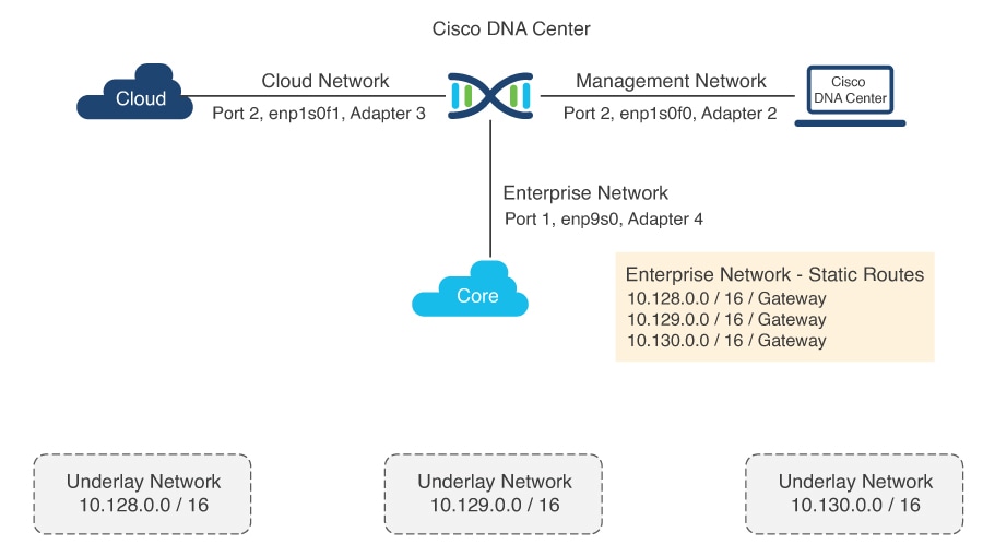
Figure 2. Static IP routing design
For a multi-home design, add a static route on Catalyst Center to resolve the IP reachability issue. You can add a static route during the initial Catalyst Center configuration or later using a maglev command. Do not use the Linux route command, because maglev APIs might not retrieve the correct information if the route is modified using the route command.
For a single-home design, verify routing between the seed device and Catalyst Center.
Follow these steps to add a static route on Catalyst Center:
Procedure
1.
On the Catalyst Center console, enter the command sudo maglev-config update.
The configuration wizard opens.
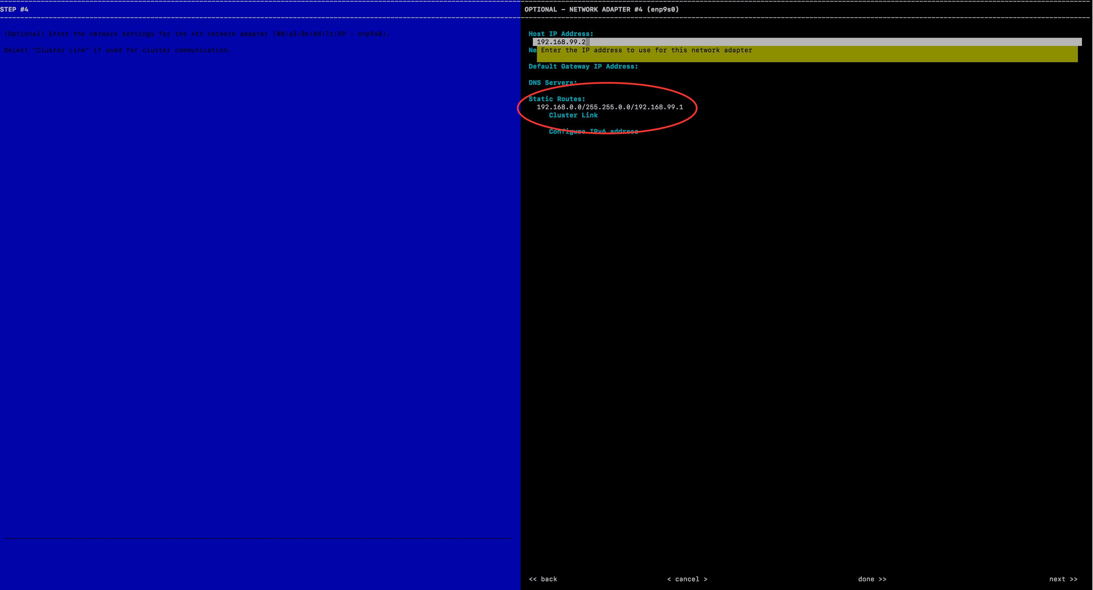
2.
Enter the static route and click Next.
The config wizard validates and configures host networking.
3.
Ensure that you select the correct interface to add the static route. If the correct interface is not displayed, click Next until it appears.
4.
Leave the Network Proxy field blank. If proxy validation fails, skip the proxy settings.
5.
To apply the changes to the controller, click Proceed.
Adding a static route takes five to six minutes (5-6 minutes). Ignore any warning messages.
Verify the PnP agent initial state
Procedure
1.
Before starting LAN automation, make sure that the PnP agent is in System Configuration Dialog state.
FIPS: Flash Key Check : Key Not Found, FIPS Mode Not Enabled
cisco C9300-24T (X86) processor with 1418286K/6147K bytes of memory.
Processor board ID FCW2137G032
2048K bytes of non-volatile configuration memory.
8388608K bytes of physical memory.
1638400K bytes of Crash Files at crashinfo:.
11264000K bytes of Flash at flash:.
0K bytes of WebUI ODM Files at webui:.

Base Ethernet MAC Address          : f8:7b:20:48:d8:80
Motherboard Assembly Number        : 73-17952-06
Motherboard Serial Number          : FOC21354B06
Model Revision Number              : A0
Motherboard Revision Number        : A0
Model Number                       : C9300-24T
System Serial Number               : FCW2137G032


%INIT: waited 0 seconds for NVRAM to be available


         --- System Configuration Dialog ---

Would you like to enter the initial configuration dialog? [yes/no]:
2.
Do not press Yes or No. Leave the device in the same state.
Note
If the device does not stop at this initial prompt and moves ahead, check the device config-register value using the CLI command show ver | inc register. In some cases, the value might be 0x142. Change the config-register value to 0x102 or 0x2102 and save the configuration. Check the CLI again; it shows Configuration register is 0x142 (will be 0x102 at next reload).
If the device comes up with the older config-register value even after changing the value to 0x102 or 0x2102 and reloading the device, configure no system ignore startupconfig switch all on the device, save the configuration, and reload.
For Cisco Catalyst 9000 series switches, use pnpa service reset no-prompt.
3.
Follow the same steps (Step 1 and Step 2) for stack switches.
Allow extra time to make sure that all members in the stack are up. Do not start LAN automation until all switches are up.
LAN automation always begins on the active switch. When all switches in a stack are booted together, the switch with the lowest MAC address (assuming no switch priority is configured) becomes active. The switch with the second lowest MAC address becomes the standby, and so on. Some customers require the first switch to always be active. In this case, if all the switches are booted together and the first switch does not have the lowest MAC address, it does not become the active switch. To ensure that the first switch is active, boot the switches in a staggered manner: boot Switch 1; after 120 seconds, boot Switch 2, and so on. This approach ensures that the switch becomes active in the correct order—Switch 1 is active, Switch 2 is standby, and so on. However, after a reload, the order may change because switches obtain their role based on their MAC address.
To make sure that the switches maintain their order after reload, it is a good practice to assign switch priorities to ensure that the switches always come up in the same order. The highest priority is 15. During LAN automation, the priority of active switch is set to 15 by default. The priority of other switches is not altered. When priorities are assigned, they take precedence over the switch MAC address. Assigning switch priorities does not change the NVRAM configuration. The values are written to ROMMON and persist after reload or write erase. Refer to this sample code:
3850_edge_2#switch 1 priority ?
  <1-15>  Switch Priority
3850_edge_2#switch 1 priority 14
WARNING: Changing the switch priority may result in a configuration change for that switch. Do you want to continue?[y/n]? [yes]: y
You might have to clean up the switch after assigning priorities because some certificates are configured on the switch during boot up. For instructions on cleaning up the switch, see PnP Agent Initial State.
Note
Do not start LAN automation until all switches in the stack are up.
If you are consoled in to the standby/member switches, do not press Enter, even though the screen says console is now available, Press RETURN to get started. Monitor the active switch, which should be at the System Configuration Dialog state.
If LAN automation is already running and you do not want to stop it, shut the seed link connecting to the PnP agent. That way, discovery doesn't occur until you are ready to bring up the link.
Port connections and license levels
Before starting LAN automation, verify the port connections and the license level on the devices.
Connect PnP agents directly to seed devices. Do not connect PnP agents to any other network (for example, the management network) or any network that can provide DHCP through another server on VLAN 1.
Ensure that the seed ports connected to the PnP agents use Layer 2 and are in the default state. For example, ports on Cisco Catalyst 6500 and 9500H switches use Layer 3 by default.
Ensure that the port on the primary seed that connects to the PnP agents does not block STP.
Ensure that the PnP agent is running the Advantage license level.
Remove a device from inventory
This section applies to devices that were discovered or LAN automated at any point.
If the devices to discover in an upcoming LAN automation session are already present in the inventory, remove them from inventory.
Before you begin
If a device was provisioned and added to the fabric, remove it from the fabric and unprovision it. Then, remove it from the inventory.
Procedure
1.
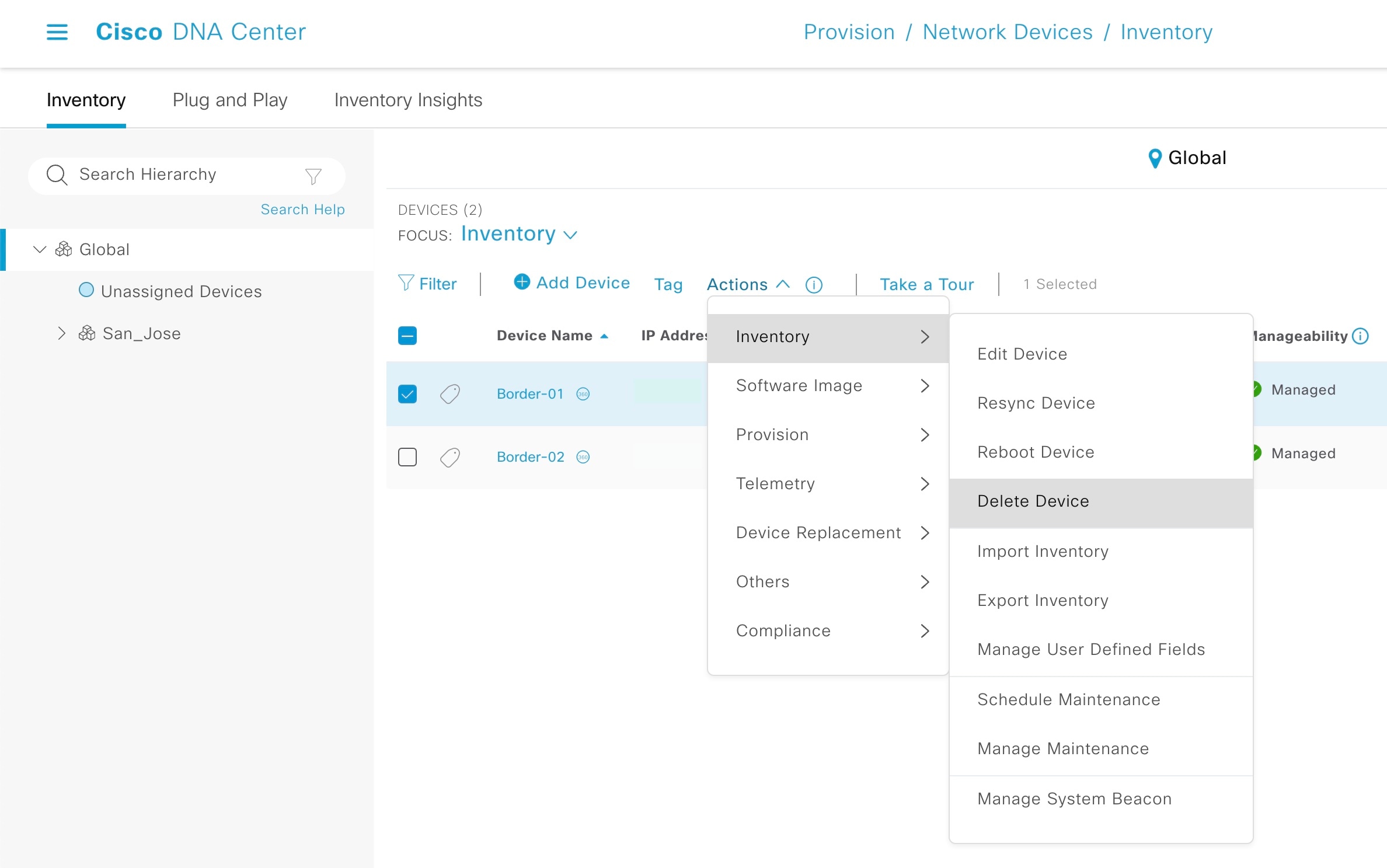
From the Catalyst Center home page, click the menu icon and chooseProvision > Inventory.
2.
Filter the devices by Serial Number.
3.
Choose a device and from the Actions drop-down list, choose Inventory > Delete Device.
Remove devices from PnP before discovery
Before starting a LAN automation session, check whether the devices you want to discover are already listed in PnP. Remove them from PnP so that device discovery works as intended.
Procedure
1.
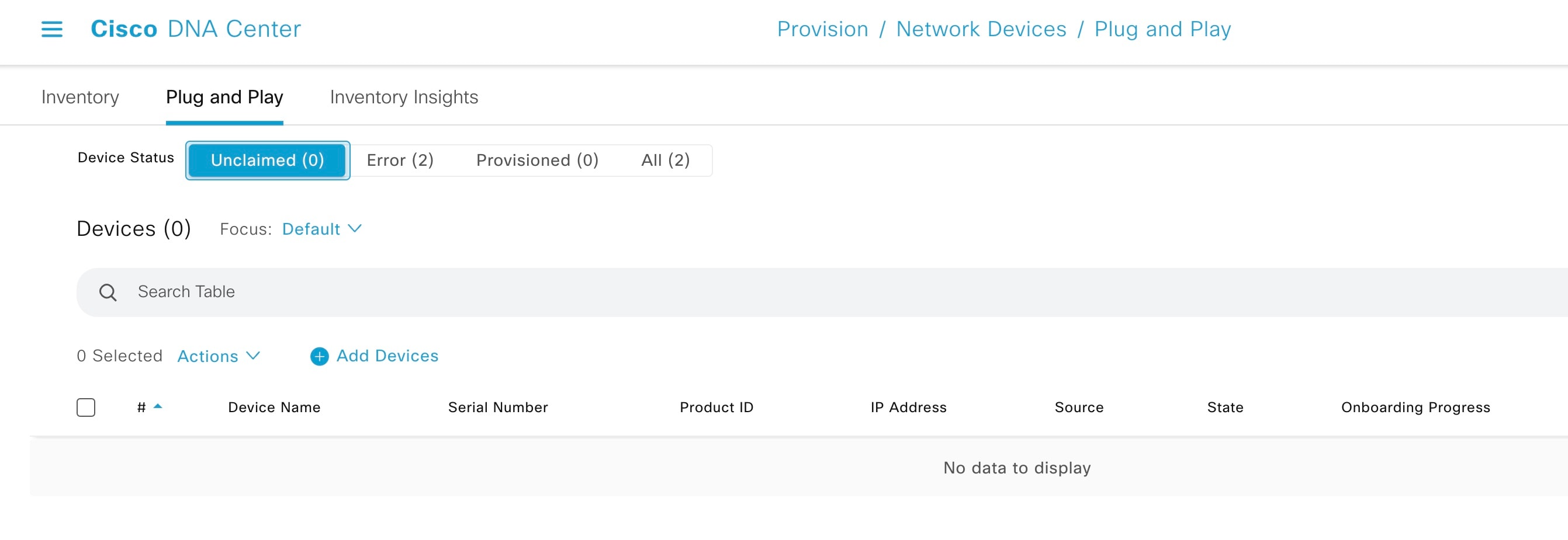
From the Catalyst Center home page, click the menu icon and chooseProvision > Plug and Play.
2.
From the Device Status filter, choose Unclaimed. Make sure that the device (Serial Number) being discovered is not available under Unclaimed.
3.
If the device is available, log in to the device console and remove the PnP profile.
[on PNP agent]

3850_edge_2#show run | sec pnp-zero-touch
pnp profile pnp-zero-touch
 transport https ipv4 192.168.99.2 port 443

3850_edge_2#conf t
Enter configuration commands, one per line.  End with CNTL/Z.
3850_edge_2(config)#no pnp profile pnp-zero-touch
3850_edge_2
For Cisco IOS XE 16.12.x or later, use this command:
pnpa service reset no-prompt
4.
Check the check box next to the device in the Unclaimed section and choose Actions > Delete.
Verify the PnP agent mode
The PnP agent must be in INSTALL mode for image upgrade during LAN automation.
Image upgrade through LAN automation occurs in the background.
Note
For modular switch platforms (Catalyst 9400 and 9600 series) with chassis plus supervisor, day-zero image upgrade is not supported. Instead, use day-n SWIM for image upgrade for these series of modular chassis.
Procedure
1.
Under Design > Image Repository, check whether a golden image is selected for the discovered device.
After PnP discovers the device, Catalyst Center checks if a golden image is marked for the switch family (Cisco Catalyst 9300 or 3850). If the golden image is marked and the discovered device is not running it, LAN automation upgrades the discovered device to the golden image. If not, Catalyst Center skips the image upgrade and pushes the initial device configuration.
2.
Ensure that the discovered device is running in INSTALL mode to allow LAN automation to upgrade the image. If the device is in BUNDLE mode, LAN automation will not upgrade the image.
Use the show version command to check the device mode.
3.
If the device is in BUNDLE mode and you want to proceed with LAN automation, remove the golden image for the relevant switch family under Design > Image Repository.