Simulate VPN

VPN model

A VPN model is a representation of a virtual subnetwork within the overall network architecture. Viewing and simulating VPN within Cisco Crosswork Planning helps with many network tasks and answers these questions:

  • Which VPNs are on my network? Where and how are they configured?

  • Which VPNs are using congested interfaces?

  • Which VPNs will experience congestion under any of a given list of failure scenarios?

  • Which failure scenarios cause the worst-case congestion or latency for a VPN?

There are many varieties of VPNs. For example, there are Layer 2 (L2) VPNs and Layer 3 (L3) VPNs, each with different categories within it, as well as vendor-specific VPN implementations. Each VPN type has its own specific configuration and terminology. The Cisco Crosswork Planning VPN model supports a number of these VPN types based on either route-target or full-mesh connectivity.

VPN objects

This section lists the VPN objects and their descriptions with examples for both Layer 2 and Layer 3 VPN configurations.

Object

Description

Examples

VPNs

A set of VPN nodes that can exchange data with each other.

  • Layer 2 VPN: The VPN represents an individual VPLS containing Virtual Switch Interfaces (VSIs).

  • Layer 3 VPN: The VPN represents sets of VRFs associated with a set of VPN nodes that forward traffic between themselves. This set of VRFs signifies a single customer or service.

VPN nodes

Connection points in a VPN. They exist on standard nodes, and each node can contain multiple VPN nodes. A VPN node can be in only one VPN.

  • Layer 2 VPN: The VPN node represents the VSIs configured on each router.

  • Layer 3 VPN: The VPN node represents the VRF instances configured on each router.

VPN topology and connectivity

VPN topology and connectivity is a network configuration that

  • are established through Route Targets (RTs) or through a full mesh of VPN nodes

  • enables Cisco Crosswork Planning to calculate which demands between VPN nodes carry traffic for a particular VPN, and

  • allows calculation of VPN vulnerability to certain failure and congestion scenarios.

A demand is associated with a VPN, meaning it carries traffic for that VPN, if these conditions are true:

  • Two VPN nodes are in the same VPN.

  • Demand is in the same service class as the VPN.

  • Only for VPNs with RT connectivity, the RT export property of one VPN node must match the RT import property of another VPN node.

After demands are associated with the VPN, this configuration simulates the associated access circuits exchanging traffic as if they were on the same LAN. Note that a demand associated with a VPN can additionally contain other traffic that is for that VPN.

VPN connectivity types

The Connectivity property is set in the Add/Edit VPN page.
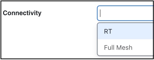
VPN connectivity options

This table compares connectivity types and their characteristics.

Connectivity

Description

RT

Route targets model the more complex connectivity used in Layer 3 VPNs, such as hub-and-spoke networks. Here, the VRFs exchange data with one another based on the matching of RT export and RT import properties set for each VPN node. However, having an import/export pair does not create bidirectional communication. Instead, traffic flows in the opposite direction of the routed advertisements.

For example, if node A’s RT import matches node B’s RT export, traffic can flow from node A to B. For traffic to flow from node B back to node A, node B must have an RT import that matches an RT export of node A. This combination of matching imported and exported RTs defines which VPN nodes can exchange data. The VPN name identifies the VPN itself.

Full Mesh

Full mesh connectivity refers to a complete mesh of connections between VPN nodes in a VPN where they can all communicate with each other. This connectivity is typical in a VPLS, where all VSIs identify one another based on a common AGI.

VPNs

A VPN is a network construct that

  • consists of a set of VPN nodes that can exchange data within it

  • has key properties that uniquely identify the VPN, and

  • defines how the traffic within the VPN is routed.

VPN properties

These are the key properties of the VPNs:

  • Name: Unique name of the VPN.

  • Type: Type of VPN. The options are VPWS, VPLS, or L3VPN.

  • Connectivity: Determines how Cisco Crosswork Planning calculates connectivity and associated demands for VPNs. The options are:

    • Full Mesh: Connectivity is between all nodes in the VPN. Cisco Crosswork Planning ignores the RT import and RT export properties of the VPN nodes.

    • RT: Connectivity is based on the RT import and RT export properties of its VPN nodes.

  • Service class: Service class associated with the VPN.

Once the VPN is created, it appears in the VPN drop-down list of VPN nodes.

Create VPNs

You can create new VPNs and then later add VPN nodes to them (refer to Add VPN nodes to VPNs).

Create new VPNs

Use this task when you need to establish new VPN connections in your network design plan. You can create different types of VPNs including L3VPN, VPLS, and VPWS with various connectivity and service configurations.

Procedure

Step 1

Open the plan file (refer to Open plan files). It opens in the Network Design page.

Step 2

From the toolbar, choose Actions > Insert > VPNs > VPN.

Alternatively, in the Network Summary panel on the right side, click The Network Design page displays the steps to create new VPNs, highlighting the VPNs tab in the Network Summary panel and the Show/hide tables icon for visibility options. in the VPNs tab.

The VPNs tab is available under the More tab. If it is not visible, then click the Show/hide tables icon (The VPNs tab in the Network Summary panel displays options for creating new VPNs, including L3VPN, VPLS, and VPWS.) and check the VPNs check box.

Step 3

In the Name field, enter a unique name for the VPN.

Step 4

From the Type drop-down list, choose a VPN type.

The options are L3VPN, VPLS, and VPWS.

Step 5

Select the Connectivity type. The options are RT or Full Mesh.

Step 6

Select the Service class for the VPN.

Step 7

Click Add.

Step 8

(Optional) Add VPN nodes to the newly created VPN. For more information, refer to Add VPN nodes to VPNs.


The new VPN is created with the specified configuration settings and appears in your plan file.

VPNs table

The VPNs table lists the VPN properties, its associated service class, traffic, and the number of VPN nodes within that VPN (Table 1). For information on QoS measurements, refer to Simulate Quality of Service (QoS). For information on the Worst-Case columns not listed here, refer to Table 1.


Note


  • Because the traffic and QoS calculations are based on all interfaces within the VPN for the service class specified for that VPN, the plot view might differ from the table. For example, the plot view could show Internet traffic while a VPN carrying voice traffic is selected.

  • All traffic and QoS violations are based on traffic carried by all interfaces used by the VPN for the service class defined for that VPN.


Table 1. VPNs table columns

Column

Description

Service class

Service class associated with this VPN. All values within the table are associated with this service class.

Num nodes

Number of VPN nodes in this VPN.

Util meas

The maximum measured utilization of all interfaces used by this VPN.

Util sim

The maximum simulated utilization of all interfaces used by this VPN.

Total src traff meas

Total amount of measured source traffic on this VPN.

Total dest traff meas

Total amount of measured destination traffic on this VPN.

QoS violation sim

Maximum QoS violation under normal operations for all simulated traffic for all interfaces used by this VPN. If the number is positive, there is a violation.

QoS violation sim (%)

QoS violation as a percent of the total simulated interface capacity.

QoS violation meas

Maximum QoS violation under normal operations for all measured traffic for all interfaces used by this VPN. If the number is positive, there is a violation.

QoS violation meas (%)

QoS violation as a percent of the total measured interface capacity.

Latency

Maximum latency of all demands used by this VPN.

Tags

User-defined identifiers that makes it easy to group VPNs.

VPNs are not selectable from the network plot. You can only select and filter VPNs only through tables. When selected, all VPN nodes within the VPN are highlighted in the plot (VPN nodes within a VPN).

Identify interfaces used by VPNs

Use this task to identify which interfaces are associated with a specific VPN and visualize the VPN in the network plot.

Procedure


Step 1

Select the required VPN from the VPNs table.

Step 2

Click > Filter to interfaces.

Note

 
Utilization measurements might be different between the tables because the VPN table calculates measurements only for the service class associated with that VPN.

Step 3

Select the filtered interfaces to see the VPN outlined in the network plot.


The system displays the interfaces associated with the selected VPN. When you select the filtered interfaces, the VPN appears outlined in the network plot for visual representation.

VPN node properties

VPN nodes are defined by the properties that determine which VPNs the nodes belong to and how the demands are routed.

  • Site: Name of the site on which the VPN node resides.

  • Node: Name of the node on which the VPN node resides. This node name corresponds to the one in the Nodes table.

  • Type: The type of VPN. The options include VPWS, VPLS, or L3VPN. Alternatively, you can enter a string value to create a new one. Once entered, the new VPN type appears in the drop-down list and is available for other VPN nodes and VPNs.

  • Name: Name of the VPN node.

  • VPN: Name of the VPN in which this VPN node resides. The drop-down list shows existing VPNs of the same type set in the Type field. You can create a VPN node without setting its VPN, but without it, the VPN node is not included in simulations as a member of any VPN.

  • Description: Description for the VPN node.

    To simulate RT connectivity, you must set the VPN Connectivity property to RT and then set the RT import and RT export properties on the individual VPN nodes within it.

  • RT import and RT export: The pairing of RT values identifies which VPN nodes connect with each other. For more information, refer to VPN topology and connectivity.

  • RD: Route Distinguisher (RD) uniquely identifies routes within a VRF as belonging to one VPN or another, thus enabling duplicate routes to be unique within a global routing table.

Create VPN nodes

Use this task to create VPN nodes.

Procedure


Step 1

Open the plan file (refer to Open plan files). It opens in the Network Design page.

Step 2

From the toolbar, choose Actions > Insert > VPNs > VPN node.

Alternatively, in the Network Summary panel on the right side, click The VPN nodes tab in the Network Summary panel allows users to manage and configure VPN nodes within the network setup. in the VPN nodes tab.

The VPN nodes tab is available under the More tab. If it is not visible, then click the Show/hide tables icon (The VPN nodes tab in the Network Summary panel allows users to manage and configure VPN nodes within the network setup.) and check the VPN nodes check box.

Step 3

Click The VPN nodes tab in the Network Summary panel allows users to manage and configure VPN nodes within the network setup..

Step 4

Enter the VPN node configuration details.

  1. In the Site and Node fields, choose the site in which the VPN node will exist, and choose the node on which the VPN node is being configured.

  2. From the Type drop-down list, choose a VPN type. The options are: L3VPN, VPLS, and VPWS.

  3. In the Name field, enter the name of the VPN node, which does not have to be unique.

  4. From the VPN drop-down list, choose the VPN to which you are adding this VPN node. If you do not see the VPN that you expect to see, check if you have selected the correct VPN type in the Type drop-down list.

  5. Optionally, enter a description that identifies the VPN node. For example, a customer name might be helpful.

  6. If the Connectivity for the VPN is RT, enter the applicable route targets in the RT import and RT export fields. All VPN nodes with the same RT import as another VPN node's RT export can receive traffic from that VPN node. Those VPN nodes with the same RT export as another VPN node's RT import can send traffic to that VPN node.

  7. Optionally, in the RD field, enter a route distinguisher.

Step 5

Click Add to create the VPN node.


The VPN node is created and appears in the VPN nodes table. The VPN node is now associated with the specified site, node, and VPN instance with the configured connectivity settings.

Add VPN nodes to VPNs

Use this task to add VPN nodes to a specific VPN.

Procedure


Step 1

Open the plan file (refer to Open plan files). It opens in the Network Design page.

Step 2

In the Network Summary panel on the right side, select one or more VPN nodes in the VPN nodes table and click A flowchart illustrating the steps to add VPN nodes to existing VPNs for effective network organization and management. The chart outlines the process and options available for editing VPN nodes..

Note


If you are editing a single VPN node, you can also use the The diagram illustrates the process of adding VPN nodes to VPNs, highlighting the steps involved and the options available in the user interface. > Edit option under the Actions column.

Step 3

In the VPN drop-down list, choose the VPN to which you are adding the VPN nodes. If you do not see the VPN that you expect to see, check if you have selected the correct VPN type in the Type drop-down list.

Step 4

Save the changes.


The VPN nodes are successfully added to the selected VPN and the configuration is saved.

VPN nodes table

The VPN nodes table lists the VPN node properties. It also includes columns that show each VPN nodes' relationship within the VPN and its traffic.

Table 2. VPN nodes table

Column

Description

Total connect

Number of VPN nodes that are connected to this VPN node as defined by the RT Import and RT Export pairings. These may or may not be in the same VPN.

VPN connect

Number of VPN nodes that are connected to this VPN node and are in the same VPN as defined by the VPN column.

Num VPN nodes

Number of nodes in the VPN that this VPN node belongs to as defined by the VPN column. This value is "na" if the VPN node does not belong to a VPN.

Src traff meas

Total amount of measured traffic entering the VPN at this node (source traffic).

Dest traff meas

Total amount of measured traffic leaving the VPN at this node (destination traffic).

Tags

A user-defined identifier that makes it easy to group VPN nodes into a single VPN. If you give a VPN node a tag, when you create a VPN later, you can identify its VPN nodes using tags.

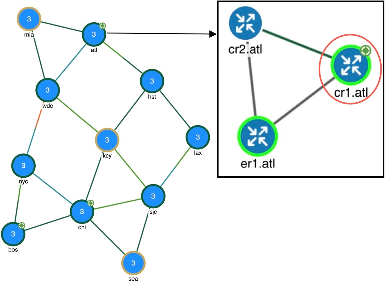
Once selected from the VPN nodes or VPNs table, the associated site and the nodes within that site appear with a green circle on it (VPN nodes within a VPN).


Note


VPN nodes are not selectable from the network plot. You can only select and filter to them through tables.


Figure 1. VPN nodes within a VPN
VPN nodes within a VPN

Layer 3 VPN example

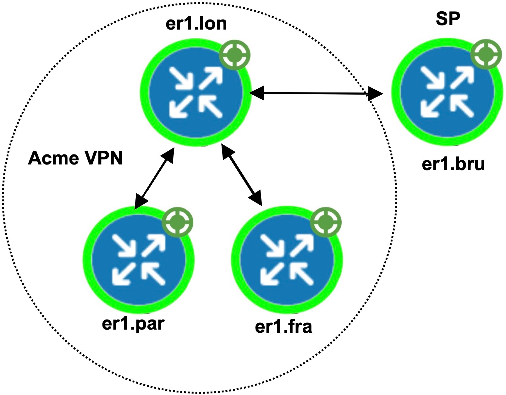
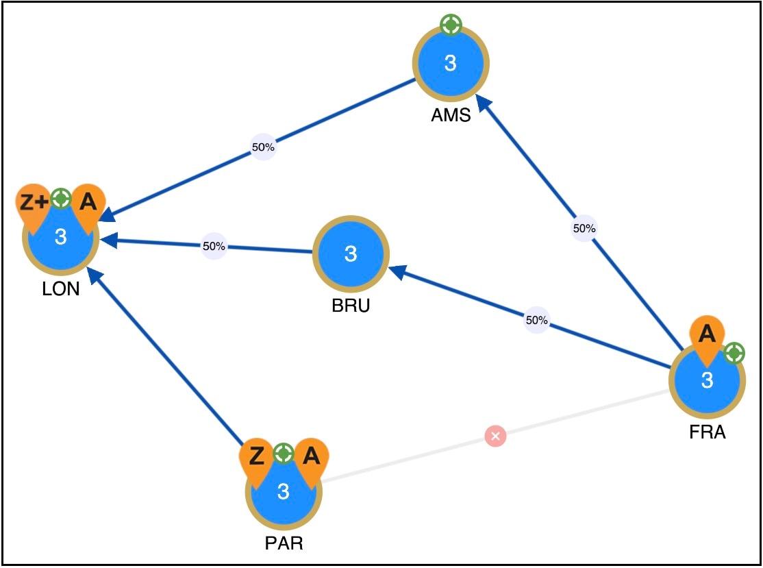
This example illustrates a scenario where the Acme manufacturing company has three offices, but permits the two branch (er1.par and er1.fra) offices to exchange data only with headquarters (er1.lon). Additionally, the headquarters communicates with an SP VPN node (er1.bru) that is not in the Acme VPN.

VPN configuration details

Example topology

Example RT connectivity and Acme VPN footprint shows the footprint of the Acme VPN and the RTs set for all VPN nodes in this example.

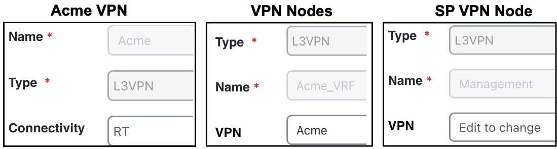
  • The VPN is named Acme, and it is set to a Connectivity of RT and a Type of L3VPN.

  • In turn, each branch office is set to the Acme VPN with a Type of L3VPN.

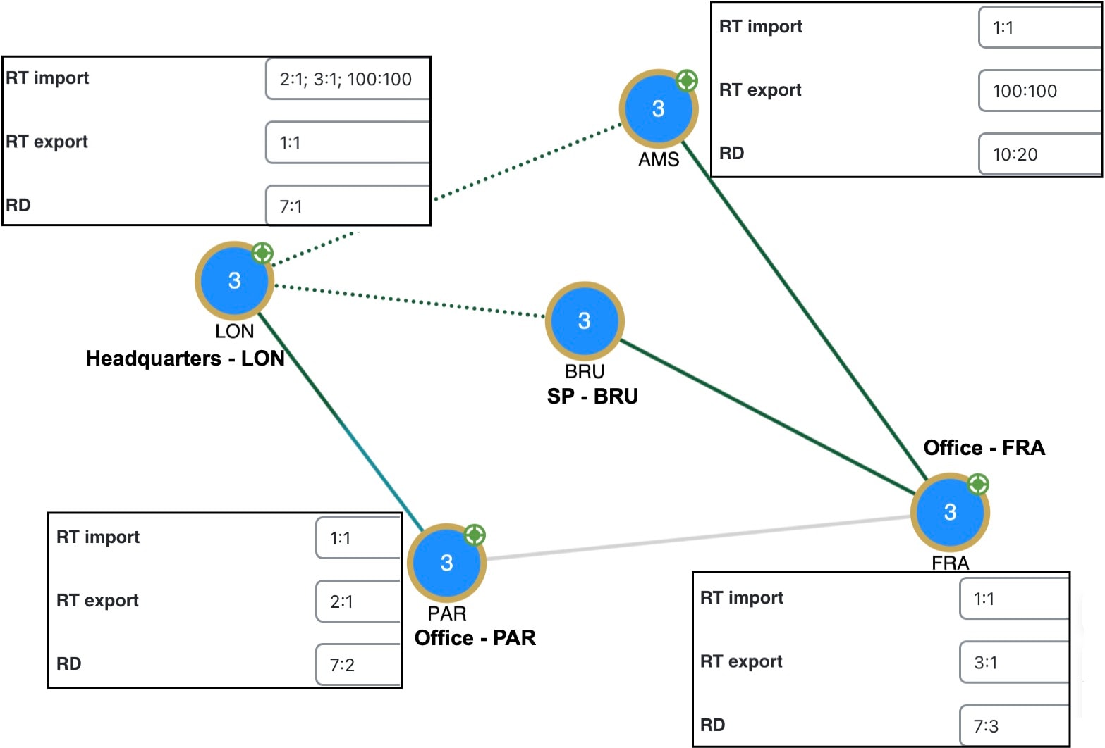
  • To exchange data with two other VPN nodes in the Acme VPN, headquarters (er1.lon) imports the offices' exported route targets of 2:1 (er1.par) and 3:1 (er1.fra).

  • In turn, headquarters (er1.lon) exports a route target of 1:1. All three other VPN nodes import it (both offices and the SP VPN node).

  • Because the SP VPN node (er1.bru) is not in the Acme VPN, its communication with er1.lon is not within the context of the Acme VPN.

VPN settings

The VPN footprint in Example RT connectivity and Acme VPN footprint shows that if the circuit between er1.fra and er1.bru becomes congested or fails, the VPN is impacted. However, a failure of the circuit between the two branch offices is not impacted. This failure is illustrated in Example failure between branch offices in the Acme VPN, which shows that none of the demands associated with the VPN are rerouted.

Figure 2. Example RT connectivity and Acme VPN footprint
Example RT connectivity and Acme VPN footprint
Figure 3. Example failure between branch offices in the Acme VPN
Example failure between branch offices in the Acme VPN

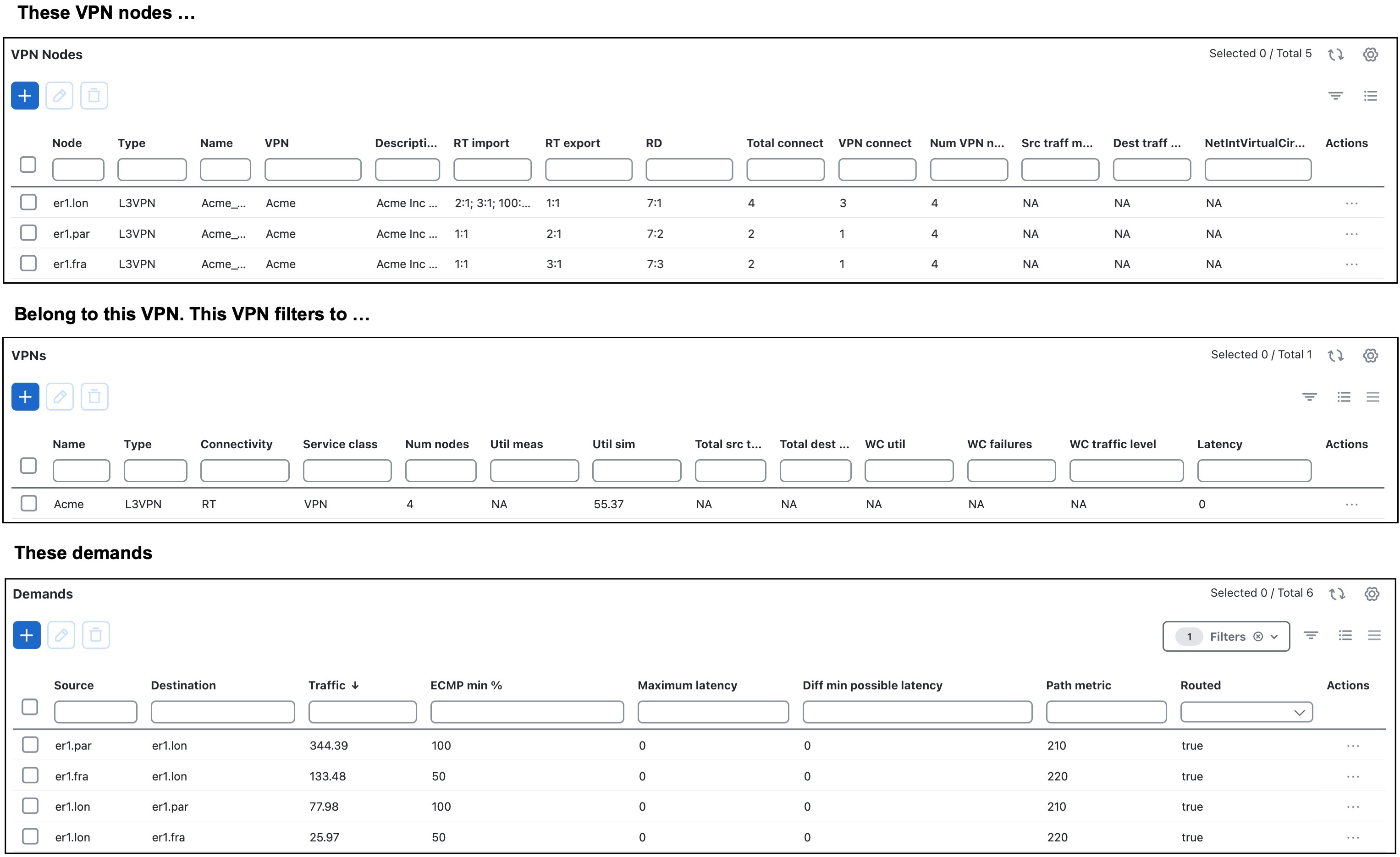
For this example, VPN nodes belonging to Acme VPN, and Acme VPN filtered to demands illustrates the VPN nodes belonging to Acme VPN and the filtering of the Acme VPN to its associated demand traffic. It also shows the calculations of the Total connect and VPN connect columns in the VPN Nodes table.

  • The Total connect for the VPN node residing on er1.lon headquarters is the highest because it exchanges data with three other VPN nodes. Each of the offices and the service provider VPN node have 2 in the Total connect column.

  • The VPN connect for the VPN node at the er1.lon headquarters is the highest because it exchanges data with and is in the same VPN as the two offices. All three VPN nodes share the same VPN name.

    Each office has 1 in the VPN connect column because it communicates with only one VPN node in the same VPN.

    The service provider VPN node (er1.bru) has 0 VPN connects because it is not part of the Acme VPN.

Figure 4. VPN nodes belonging to Acme VPN, and Acme VPN filtered to demands
VPN nodes belonging to Acme VPN, and Acme VPN filtered to demands

VPN simulation analysis

When running the Simulation analysis tool, you can record worst-case utilization and latency for VPNs. Then, you can select a VPN to fail to its worst-case utilization or worst-case latency using the The VPN simulation analysis displays the updated columns in the VPNs table after running the simulation, along with options for testing VPN failures. > Fail to WC or Fail to WC latency options, respectively.


Note


All calculations are based on traffic carried by all interfaces used by the VPN for the service class defined for that VPN.
VPN simulation analysis

Columns updated in the VPNs table after simulation analysis

These columns are updated in the VPNs table after completion of Simulation analysis.

Table 3. Updated columns in the VPNs table

Column

Description

WC util

Worst-case VPN utilization over all failure scenarios.

WC failures

Failures causing the worst-case utilization of the VPN.

WC traffic level

Traffic level causing the utilization of the interface identified in the WC util column.

WC QoS violation

Highest worst-case QoS violation for all interfaces used by this VPN. A QoS violation is equal to the worst-case traffic minus the worst-case capacity permitted (worst-case QoS bound).

WC QoS violation (%)

Highest worst-case QoS violation for all interfaces in this VPN expressed as a percentage of total capacity.

WC latency

Maximum VPN latency over failure scenarios considered.

WC latency failures

Failures causing the worst-case VPN latency.