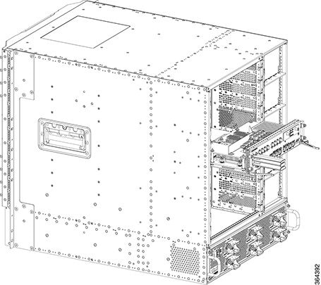
Installing the Supervisor in the Cisco cBR Chassis
This section provides information on installing the Supervisor.
Check if your hardware might have a supervisor card. For supervisor cards that are shipped as a spare module, the supervisor card bootflash would be empty. Ensure that you manually copy the image on the bootflash to avoid issues while booting.
 Note |
Any time a physical Online Insertion/Removal (OIR) is performed, the removed module must be left out 30-60 seconds before re-inserting it in the cBR-8 chassis. |
Installing the Supervisor 160G
Installing the Supervisor PIC in the Cisco cBR Chassis
Perform this procedure to install the following PICs:
-
Supervisor PIC
-
Blank PIC for the Supervisor
Before you begin
 Warning |
If you are adding a new Supervisor PIC or upgrading the existing Supervisor PICs, ensure that the power modules installed in the chassis are adequate to support the Supervisor PICs. |
-
Attach an ESD-preventive wrist strap to your wrist and connect the other end to the grounding lug connected to the chassis.
-
Be aware of the weight and size of the equipment. Handle it with care.
Restrictions
-
If you are using a single Supervisor, you must install the Supervisor PIC in the slot corresponding to the Supervisor Card.
Note
In the Cisco cBR-8 router,-
Slot 4/1 for the Supervisor PIC corresponds to slot SUP0 for the Supervisor Card.
-
Slot 5/1 for the Supervisor PIC corresponds to slot SUP1 for the Supervisor Card.
-
Required Tools and Equipment
-
ESD-preventive wrist strap
-
Supervisor PIC or blank PIC for the Supervisor
-
3/16" flat-blade torque screwdriver
Procedure
| Step 1 |
Grasp the faceplate of the PIC with one hand and place your other hand under the PIC to support its weight. |
||
| Step 2 |
Carefully align the PIC with the plastic guides in the slot. |
||
| Step 3 |
Slide the PIC into the slot applying even pressure using both your hands until it is within an inch of full insertion. |
||
| Step 4 |
Open the ejector levers and fully insert the PIC into the slot applying even pressure on both sides until it mates with the midplane connectors.
 |
||
| Step 5 |
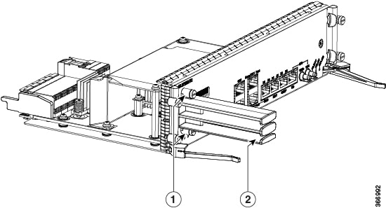
Simultaneously pivot both the ejector levers towards each other until they cannot be pivoted any further. 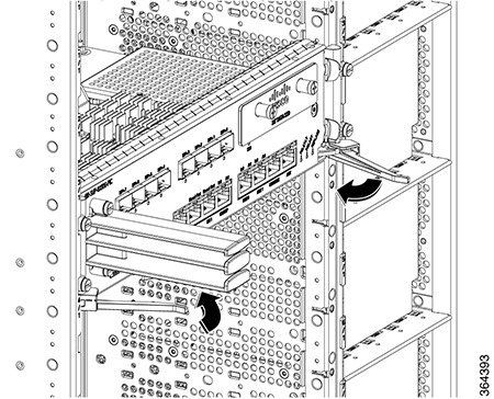 |
||
| Step 6 |
Tighten the four captive screws using a 3/16" flat-blade torque screwdriver with a torque of 6-8 in-lb (0.68-0.90 Nm) to secure the PIC. |
What to do next
-
If you are using a single Supervisor PIC, install a blank PIC for the Supervisor in the empty slot.
-
Install the Supervisor PIC cable management bracket (recommended).
-
Install the Supervisor Card (if not already installed).
Installing the Supervisor PIC Cable Management Bracket
The Supervisor PIC cable management bracket is shipped separately in the chassis accessory kit. It has a smaller slot for fiber-optic cables and a larger slot for the RJ-45 cables.
Before you begin
-
Attach an ESD-preventive wrist strap to your wrist and connect the other end to the grounding lug connected to the chassis.
-
Install the Supervisor PIC (recommended).
Required Tools and Equipment
-
ESD-preventive wrist strap
-
Supervisor PIC
-
Supervisor PIC cable management bracket
-
3/16" flat-blade torque screwdriver
Procedure
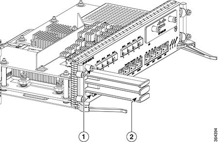
| Step 1 |
Align the captive screws on the Supervisor PIC cable management bracket with the mounting holes on the Supervisor PIC.
|
||||||
| Step 2 |
Tighten the captive screws using a 3/16" flat-blade torque screwdriver with a torque of 6-8 in-lb (0.68-0.90 Nm) to secure the Supervisor PIC cable management bracket. |
What to do next
Installing the SFP+ Modules in the Supervisor PIC
Before you begin
 Caution |
Do not install or remove the SFP+ module with fiber-optic cables still attached to it. Doing so may damage cables, cable connectors, or the optical interfaces and may interfere with the SFP+ module latching properly into its socket connector. Disconnect all cables before removing or installing an SFP transceiver module. |
-
Attach an ESD-preventive wrist strap to your wrist and connect the other end to the grounding lug connected to the chassis.
-
You must use the supported SFP+ modules. The following SFP+ modules are supported on the Supervisor PIC:
-
SFP-10G-SR
-
SFP-10G-LR
-
SFP-10G-ER
-
SFP-10G-ZR
-
SFP-10G-LRM
-
Required Tools and Equipment
-
ESD-preventive wrist strap
-
SFP+ module
Procedure
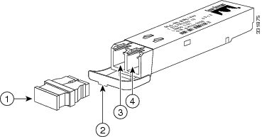
| Step 1 |
Remove the SFP+ module from its protective packaging.
|
||||||||||
| Step 2 |
Check the label on the SFP+ module to verify that you have the correct model for your network. |
||||||||||
| Step 3 |
Find the send (TX) and receive (RX) markings that identify the top side of the SFP+ module.
|
||||||||||
| Step 4 |
Align the SFP+ module in front of the socket opening. |
||||||||||
| Step 5 |
Carefully insert the SFP+ module into the socket until you feel the connector latch into place. 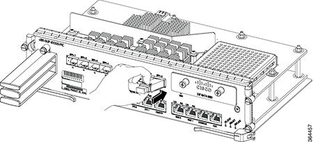 |
||||||||||
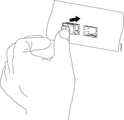
| Step 6 |
Press the SFP+ module into the slot firmly with your thumb until it is latched securely into the socket. |
||||||||||
| Step 7 |
What to do next
-
Verify if the SFP+ module is seated and latched properly. Grasp the SFP+ module and try to remove it without releasing the latch. If the SFP+ module cannot be removed, it is installed and seated properly. If the SFP+ module can be removed, reinstall it.
Installing the Supervisor Card in the Cisco cBR Chassis
Perform this procedure to install the following cards:
-
Supervisor Card
-
Blank card for the Supervisor
Before you begin
Warning |
If you are adding a new Supervisor Card or upgrading the existing Supervisor Cards, ensure that the power modules installed in the chassis are adequate to support the Supervisor Cards. |
-
Attach an ESD-preventive wrist strap to your wrist and connect the other end to the grounding lug connected to the chassis.
-
Install the Supervisor PIC (recommended).
-
Be aware of the weight and size of the equipment. Handle it with care.
Restrictions
-
If you are using a single Supervisor, you must install the Supervisor Card in the slot corresponding to the Supervisor PIC.
Note
In the Cisco cBR-8 router,-
Slot 4/1 for the Supervisor PIC corresponds to slot SUP0 for the Supervisor Card.
-
Slot 5/1 for the Supervisor PIC corresponds to slot SUP1 for the Supervisor Card.
-
Required Tools and Equipment
-
ESD-preventive wrist strap
-
Supervisor Card or blank card for the Supervisor
-
3/16" flat-blade torque screwdriver
Procedure
| Step 1 |
Loosen the captive screws on the appropriate slot using a 3/16" flat-blade torque screwdriver until the red bands are visible on the captive screws. 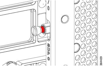 |
||
| Step 2 |
Pull the spring-loaded ejectors on the card until they release and are perpendicular to the faceplate. |
||
| Step 3 |
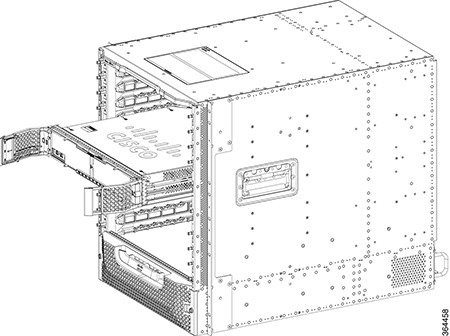
Grasp the faceplate of the card with one hand and place your other hand under the card to support its weight. |
||
| Step 4 |
Carefully align the support rails on the card with the rails in the appropriate slot. |
||
| Step 5 |
Slide and push the card into the slot applying even pressure using both your hands until it mates with its midplane connectors.
 |
||
| Step 6 |
Simultaneously pivot both the spring-loaded ejectors towards the faceplate until they make contact with the faceplate. 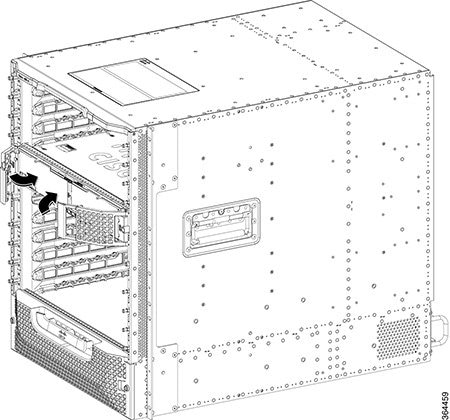 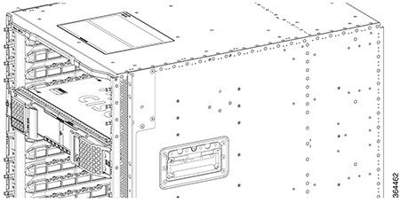 |
||
| Step 7 |
Tighten the two captive screws using a 3/16" flat-blade torque screwdriver with a torque of 10-12 lb-in (1.12-1.36 Nm) to secure the card. |
What to do next
-
If you are using a single Supervisor Card, install a blank card for the Supervisor in the empty slot.
-
Connect memory stick or flash drive to use the USB port (if required).
-
Connect cable to use the console port (if required).
Using the SFP+ Ports on the Supervisor PIC
Before you begin
-
Do not remove the protective dust plugs on the unplugged fiber-optic cable connectors and the SFP+ optical bores until you are ready to make a connection.
Required Tools and Equipment
-
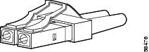
Fiber-optic cable with the LC connector
Procedure
| Step 1 |
Remove the dust plugs from the network interface cable LC connectors. Save the dust plugs for future use. |
||
| Step 2 | |||
| Step 3 |
Remove the dust plug from the SFP+ module optical bores on the Supervisor PIC. |
||
| Step 4 |
Immediately connect the fiber-optic cable with cable LC connector to the SFP+ port.
 |
What to do next
Using the DTI Ports on the Supervisor PIC
Before you begin
Required Tools and Equipment
-
RJ-45 cable
-
Clock source (DTI server)
Procedure
| Step 1 |
Connect one end of the RJ-45 cable to the DTI port on the Supervisor PIC. 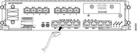 |
| Step 2 |
Connect the other end of the RJ-45 cable to the to the DTI server as a reference clock source. |
What to do next
Using the NME Ports on the Supervisor PIC
Before you begin
Required Tools and Equipment
-
RJ-45 cable
-
Switch
Procedure
| Step 1 |
Connect one end of the RJ-45 cable to the NME port on the Supervisor PIC. 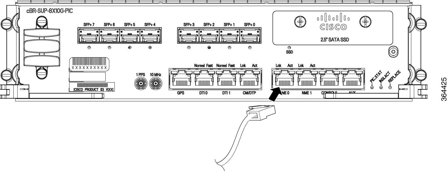 |
| Step 2 |
Connect the other end of the RJ-45 cable to a switch. |
What to do next
Using the Console Port on the Supervisor PIC
The console port provides local administrative access to the router and its command-line interface (CLI).
Before you begin
Restrictions
-
Each Supervisor PIC must have a console port connection when running a redundant configuration in the chassis.
Required Tools and Equipment
-
RJ-45 cable
-
RJ-45-to-DB-9 adapter
-
PC or terminal
Procedure
| Step 1 |
Connect one end of the RJ-45 cable to the console port on the Supervisor PIC. 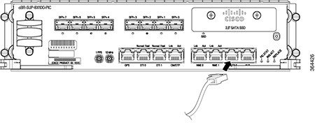 |
| Step 2 |
Connect the other end of the RJ-45 cable to the RJ-45-to-DB-9 adapter. 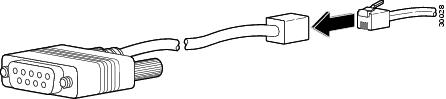 |
| Step 3 |
Connect the RJ-45-to-DB-9 adapter to the appropriate serial port on the PC or terminal. |
| Step 4 |
Power up the PC or terminal. |
| Step 5 |
Configure the PC terminal emulation software or the terminal with the following settings:
|
What to do next
Using the Auxiliary Port on the Supervisor PIC
The auxiliary port provides a connection for a terminal server to allow remote access to the router and its command-line interface (CLI).
Before you begin
Required Tools and Equipment
-
RJ-45 cable
-
RJ-45-to-DB-9 adapter
-
Terminal server
Procedure
| Step 1 |
Connect one end of the RJ-45 cable to the auxiliary port on the Supervisor PIC. 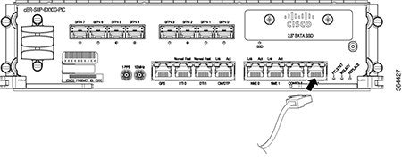 |
| Step 2 |
Connect the other end of the RJ-45 cable to the RJ-45-to-DB-9 adapter. |
| Step 3 |
Connect the RJ-45-to-DB-9 adapter to the appropriate serial port on the terminal server. |
What to do next
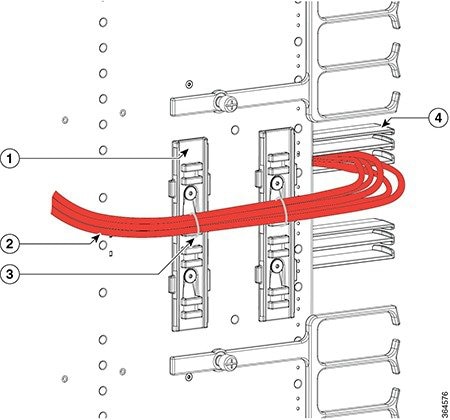
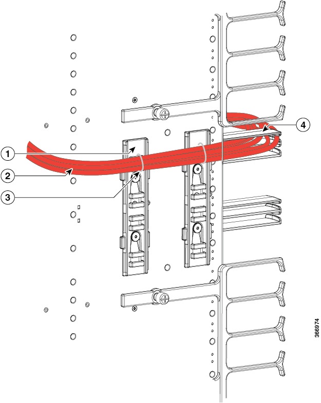
Cable Management for the Supervisor PIC in the Cisco cBR Chassis
The following accessories are used for routing the cables connected to the Supervisor PIC:
-
Supervisor PIC cable management bracket
-
Chassis-mounted cable strap-down clips
-
Chassis-mounted snap-on plastic fiber/cable routing guides
Use the upper cable management bracket and fiber/cable routing guides for routing the cables connected to the upper Supervisor PIC and the lower cable management bracket and fiber/cable routing guide for routing the cables connected to the lower Supervisor PIC.
The strap-down clips have multiple uses. They can be used:
-
to strap down cable bundles or conduit (there are multiple tie down points on each strap-down clip)
-
as a base for two snap-on plastic fiber/cable routing guides
Before you begin
-
Install the chassis-mounted cable strap-down clips and attach the snap-on plastic fiber/cable routing guides, as necessary based on the cable routing preference.
-
Connect the cables to the appropriate ports on the Supervisor PIC.
Required Tools and Equipment
-
Cable ties
Procedure
| Step 1 |
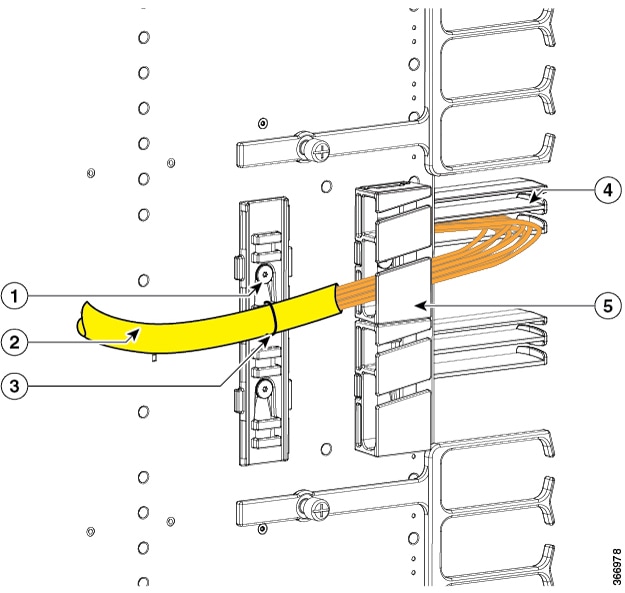
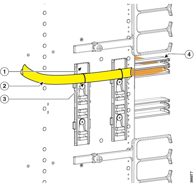
Perform the following for the fiber-optic cables connected to the Supervisor PIC:
The following figures illustrate the possible cable routing options for the fiber-optic cables connected to the Supervisor PIC: 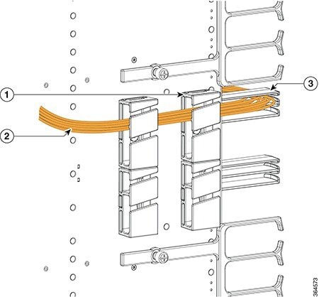
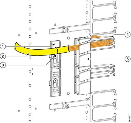
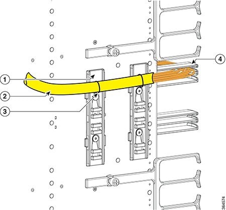
|
||||||||||||||||||||||||||||
| Step 2 |
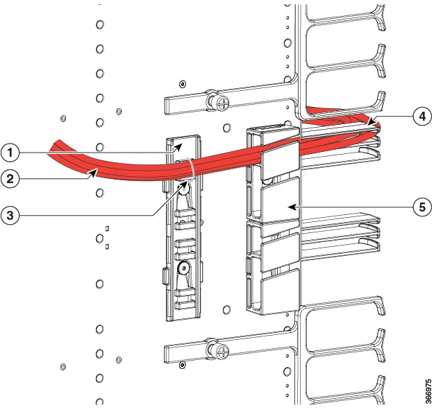
Perform the following for the RJ-45 cables connected to the Supervisor PIC:
The following figures illustrate the possible cable routing options for the RJ-45 cables connected to the Supervisor PIC: 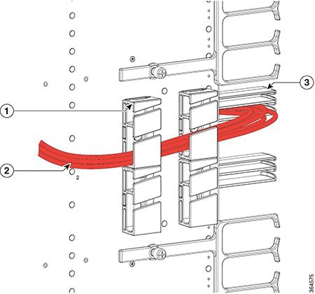
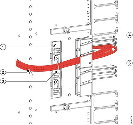
|
||||||||||||||||||||||||||||
| Step 3 |
Repeat Step 1 and Step 2 for the cables connected to the each Supervisor PIC. |
Using the USB Port on the Supervisor Card
Before you begin
Restrictions
The USB ports on the Supervisor Card are used for temporary connections. For all permanent connections, you must use the ports on the Supervisor PIC.
Required Tools and Equipment
-
Memory stick or flash drive
Procedure
| Step 1 |
Open the tethered I/O door on the Supervisor Card by pulling on the left edge of the door until the door is released from the spring-loaded ejector. 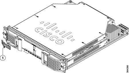
|
||||
| Step 2 |
Connect the memory stick or flash drive to the USB port on the Supervisor Card. 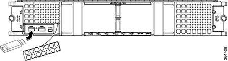 |
Using the Console Port on the Supervisor Card
Before you begin
Restrictions
-
When running a redundant configuration in the chassis, each Supervisor Card or Supervisor PIC must have a console port connection.
-
The console port on the Supervisor Card is for temporary connections. For permanent console connection, you must use the port on the Supervisor PIC.
Required Tools and Equipment
-
Console cable (with mini type-B USB connector on one end, and a type-A USB connector on the other end)
-
Exar XR21V1410 UART with USB interface
-
Cable with type-A USB connector on one end and DB-9 connector on the other end
-
PC or terminal
Procedure
| Step 1 |
Open the tethered I/O door on the Supervisor Card by pulling on the left edge of the door until the door is released from the spring-loaded ejector.
|
||||
| Step 2 |
Connect the mini type-B USB connector of the console cable to the console port on the Supervisor Card. 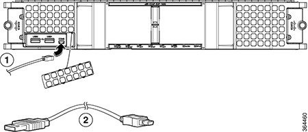
|
||||
| Step 3 |
Connect the type-A USB connector of the console cable to the Exar XR21V1410 UART with USB interface. |
||||
| Step 4 |
Connect the Exar XR21V1410 UART to the appropriate serial port on the PC or terminal using a cable with type-A USB connector on one end and DB-9 connector on the other end. |
||||
| Step 5 |
Power up the PC or terminal. |
||||
| Step 6 |
Configure the PC terminal emulation software or the terminal with the following settings:
|
Installing the Supervisor 250G
Installing the Supervisor PIC in the Cisco cBR Chassis
Perform this procedure to install the following PICs:
-
Supervisor PIC
-
Blank PIC for the Supervisor
Note |
Do not support mix use of 250G and 160G SUP and SUP-PIC. |
Before you begin
Warning |
If you are adding a new Supervisor PIC or upgrading the existing Supervisor PICs, ensure that the power modules installed in the chassis are adequate to support the Supervisor PICs. |
-
Attach an ESD-preventive wrist strap to your wrist and connect the other end to the grounding lug connected to the chassis.
-
Be aware of the weight and size of the equipment. Handle it with care.
Restrictions
-
If you are using a single Supervisor, you must install the Supervisor PIC in the slot corresponding to the Supervisor Card.
Note
In the Cisco cBR-8 router,-
Slot 4/1 for the Supervisor PIC corresponds to slot SUP0 for the Supervisor Card.
-
Slot 5/1 for the Supervisor PIC corresponds to slot SUP1 for the Supervisor Card.
-
Required Tools and Equipment
-
ESD-preventive wrist strap
-
Supervisor PIC or blank PIC for the Supervisor
-
3/16" flat-blade torque screwdriver
Procedure
| Step 1 |
Grasp the faceplate of the PIC with one hand and place your other hand under the PIC to support its weight. |
||
| Step 2 |
Carefully align the PIC with the plastic guides in the slot. |
||
| Step 3 |
Slide the PIC into the slot applying even pressure using both your hands until it is within an inch of full insertion. |
||
| Step 4 |
Open the ejector levers and fully insert the PIC into the slot applying even pressure on both sides until it mates with the midplane connectors.
 |
||
| Step 5 |
Simultaneously pivot both the ejector levers towards each other until they cannot be pivoted any further. 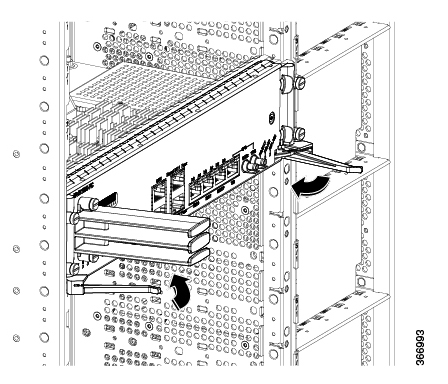 |
||
| Step 6 |
Tighten the four captive screws using a 3/16" flat-blade torque screwdriver with a torque of 6-8 in-lb (0.68-0.90 Nm) to secure the PIC. |
What to do next
-
If you are using a single Supervisor PIC, install a blank PIC for the Supervisor in the empty slot.
-
Install the Supervisor PIC cable management bracket (recommended).
-
Install the Supervisor Card (if not already installed).
Installing the Supervisor PIC Cable Management Bracket
The Supervisor PIC cable management bracket is shipped separately in the chassis accessory kit. It has a smaller slot for fiber-optic cables and a larger slot for the RJ-45 cables.
Before you begin
-
Attach an ESD-preventive wrist strap to your wrist and connect the other end to the grounding lug connected to the chassis.
-
Install the Supervisor PIC (recommended).
Required Tools and Equipment
-
ESD-preventive wrist strap
-
Supervisor PIC
-
Supervisor PIC cable management bracket
-
3/16" flat-blade torque screwdriver
Procedure
| Step 1 |
Align the captive screws on the Supervisor PIC cable management bracket with the mounting holes on the Supervisor PIC.
|
||||||
| Step 2 |
Tighten the captive screws using a 3/16" flat-blade torque screwdriver with a torque of 6-8 in-lb (0.68-0.90 Nm) to secure the Supervisor PIC cable management bracket. |
What to do next
Installing the QSFP+ or QSFP28 Transceiver Modules in the Supervisor PIC
The 40-Gigabit (GE) QSFP+ and 100 Gigabit (QSFP28) transceiver module is a hot-swappable, parallel fiber-optical module with four independent optical transmit and receive channels. These channels can terminate in another 40-Gigabit QSFP+ transceiver, or the channels can be broken out to four separate 10-Gigabit SFP+ transceivers. The QSFP+ transceiver module connects the electrical circuitry of the system with an optical external network.
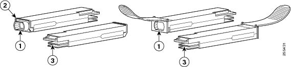
The following figure shows the 40-Gigabit optical QSFP+ transceiver. The transceiver is used primarily in short reach applications in switches, routers, and data center equipment where it provides higher density than SFP+ modules. The 100-Gigabit optical QSFP28 transceiver is similar to the 40-Gigabit optical QSFP transceiver.
|
1 |
40GBASE QSFP+ transceiver body |
3 |
Electrical connection to the module circuitry |
|
2 |
Bail-clasp latch |
The QSFP+ or QSFP28 transceiver module can have either a bail-clasp latch or a pull-tab latch. Installation procedures for both types of latches are provided.
Before you begin
Caution |
Do not install or remove the QSFP28 module with fiber-optic cables still attached to it. Doing so may damage cables, cable connectors, or the optical interfaces and may interfere with the QSFP28 module latching properly into its socket connector. Disconnect all cables before removing or installing an QSFP28 module. |
Caution |
The QSFP+ or QSFP28 transceiver module is a static-sensitive device. Always use an ESD wrist strap or similar individual grounding device when handling QSFP+ or QSFP28 transceiver modules or coming into contact with system modules. |
-
Attach an ESD-preventive wrist strap to your wrist and connect the other end to the grounding lug connected to the chassis.
-
You must use the supported QSFP28 modules. The following QSFP28 modules are supported on the Supervisor PIC:
-
QSFP-100G-SR4-S
-
QSFP-100G-LR4-S
-
QSFP-40G-SR4 with breakout cable
-
QSFP-4x10G-LR-S with breakout cable
-
QSFP-100G-SM-SR
Note
If the QSFP-100G-SM-SR module is used in the SUP 250 PIC card, the cBR-8 router chassis ambient temperature must be limited to 54ºC at sea level.
-
Required Tools and Equipment
-
Wrist strap or other personal grounding device to prevent ESD occurrences.
-
Antistatic mat or antistatic foam to set the transceiver on.
-
Fiber-optic end-face cleaning tools and inspection equipment.
Procedure
| Step 1 |
Attach an ESD wrist strap to yourself and a properly grounded point on the chassis or the rack. |
||
| Step 2 |
Remove the QSFP+ or QSFP28 transceiver module from its protective packaging. |
||
| Step 3 |
Check the label on the QSFP+ or QSFP28 transceiver module body to verify that you have the correct model for your network. |
||
| Step 4 |
For optical QSFP+ or QSFP28 transceiver modules, remove the optical bore dust plug and set it aside. |
||
| Step 5 |
For QSFP+ or QSFP28 transceiver modules equipped with a pull-tab, hold the transceiver so that the identifier label is on the top. |
||
| Step 6 |
For QSFP+ or QSFP28 transceiver modules equipped with a bail-clasp latch, keep the bail-clasp aligned in a vertical position. |
||
| Step 7 |
Align the QSFP+ or QSFP28 transceiver module in front of the module’s transceiver socket opening and carefully slide the QSFP+ or QSFP28 transceiver into the socket until the transceiver makes contact with the socket electrical connector (see the figure below). 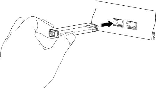 |
||
| Step 8 |
Press firmly on the front of the QSFP+ or QSFP28 transceiver module with your thumb to fully seat the transceiver in the module’s transceiver socket (see the below figure).
 |
||
| Step 9 |
For optical QSFP+ or QSFP28 transceiver modules, reinstall the dust plug into the QSFP+ or QSFP28 transceivers optical bore until you are ready to attach the network interface cable. Do not remove the dust plug until you are ready to attach the network interface cable. |
What to do next
-
Verify if the QSFP+ or QSFP28 module is seated and latched properly. Grasp the QSFP+ or QSFP28 module and try to remove it without releasing the latch. If the QSFP+ or QSFP28 module cannot be removed, it is installed and seated properly. If the QSFP+ or QSFP28 module can be removed, reinstall it.
Installing the Supervisor Card in the Cisco cBR Chassis
Perform this procedure to install the following cards:
-
Supervisor Card
-
Blank card for the Supervisor
Before you begin
Warning |
If you are adding a new Supervisor Card or upgrading the existing Supervisor Cards, ensure that the power modules installed in the chassis are adequate to support the Supervisor Cards. |
-
Attach an ESD-preventive wrist strap to your wrist and connect the other end to the grounding lug connected to the chassis.
-
Install the Supervisor PIC (recommended).
-
Be aware of the weight and size of the equipment. Handle it with care.
Restrictions
-
If you are using a single Supervisor, you must install the Supervisor Card in the slot corresponding to the Supervisor PIC.
Note
In the Cisco cBR-8 router,-
Slot 4/1 for the Supervisor PIC corresponds to slot SUP0 for the Supervisor Card.
-
Slot 5/1 for the Supervisor PIC corresponds to slot SUP1 for the Supervisor Card.
-
Required Tools and Equipment
-
ESD-preventive wrist strap
-
Supervisor Card or blank card for the Supervisor
-
3/16" flat-blade torque screwdriver
Procedure
| Step 1 |
Loosen the captive screws on the appropriate slot using a 3/16" flat-blade torque screwdriver until the red bands are visible on the captive screws. |
||
| Step 2 |
Pull the spring-loaded ejectors on the card until they release and are perpendicular to the faceplate. |
||
| Step 3 |
Grasp the faceplate of the card with one hand and place your other hand under the card to support its weight. |
||
| Step 4 |
Carefully align the support rails on the card with the rails in the appropriate slot. |
||
| Step 5 |
Slide and push the card into the slot applying even pressure using both your hands until it mates with its midplane connectors.
|
||
| Step 6 |
Simultaneously pivot both the spring-loaded ejectors towards the faceplate until they make contact with the faceplate. |
||
| Step 7 |
Tighten the two captive screws using a 3/16" flat-blade torque screwdriver with a torque of 10-12 lb-in (1.12-1.36 Nm) to secure the card. |
What to do next
-
If you are using a single Supervisor Card, install a blank card for the Supervisor in the empty slot.
-
Connect memory stick or flash drive to use the USB port (if required).
-
Connect cable to use the console port (if required).
Attaching the Optical Network Cable
Before you begin
Before removing the dust plugs and making any optical connections, follow these guidelines:
-
Keep the protective dust plugs installed in the unplugged fiber-optic cable connectors and in the transceiver optical bores until you are ready to make a connection.
-
Inspect and clean the MPO connector end faces just before you make any connections.
-
Grasp the MPO connector only by the housing to plug or unplug a fiber-optic cable.
Note |
40-Gigabit QSFP+ or QSFP28 transceiver modules are keyed to prevent incorrect insertion. |
Note |
The multiple-fiber push-on (MPO) connectors on the optical QSFP+ or QSFP28 transceivers support network interface cables with either physical contact (PC) or ultra-physical contact (UPC) flat polished face types. The MPO connectors on the optical QSFP+ or QSFP28 transceivers do not support network interface cables with an angle-polished contact (APC) face type. |
Procedure
| Step 1 |
Remove the dust plugs from the optical network interface cable MPO connectors. Save the dust plugs for future use. |
| Step 2 |
Inspect and clean the MPO connector’s fiber-optic end faces. |
| Step 3 |
Remove the dust plugs from the QSFP+ or QSFP28 transceiver module optical bores. |
| Step 4 |
Immediately attach the network interface cable MPO connectors to the QSFP+ or QSFP28 transceiver module (see the figure below). 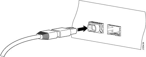 |
What to do next
Using the DTI Ports on the Supervisor PIC
Before you begin
Required Tools and Equipment
-
RJ-45 cable
-
Clock source (DTI server)
Procedure
| Step 1 |
Connect one end of the RJ-45 cable to the DTI port on the Supervisor PIC. 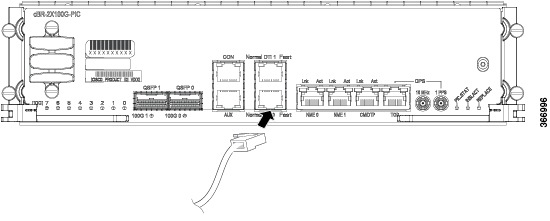 |
| Step 2 |
Connect the other end of the RJ-45 cable to the to the DTI server as a reference clock source. |
What to do next
Using the NME Ports on the Supervisor PIC
Before you begin
Required Tools and Equipment
-
RJ-45 cable
-
Switch
Procedure
| Step 1 |
Connect one end of the RJ-45 cable to the NME port on the Supervisor PIC. 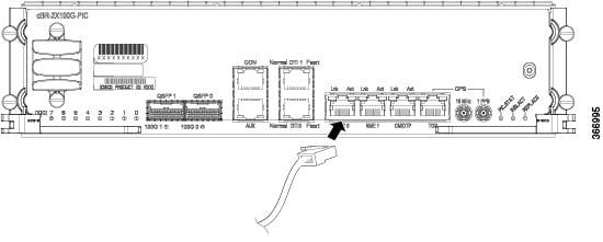 |
| Step 2 |
Connect the other end of the RJ-45 cable to a switch. |
What to do next
Using the Console Port on the Supervisor PIC
The console port provides local administrative access to the router and its command-line interface (CLI).
Before you begin
Restrictions
-
Each Supervisor PIC must have a console port connection when running a redundant configuration in the chassis.
Required Tools and Equipment
-
RJ-45 cable
-
RJ-45-to-DB-9 adapter
-
PC or terminal
Procedure
| Step 1 |
Connect one end of the RJ-45 cable to the console port on the Supervisor PIC. 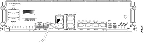 |
| Step 2 |
Connect the other end of the RJ-45 cable to the RJ-45-to-DB-9 adapter. |
| Step 3 |
Connect the RJ-45-to-DB-9 adapter to the appropriate serial port on the PC or terminal. |
| Step 4 |
Power up the PC or terminal. |
| Step 5 |
Configure the PC terminal emulation software or the terminal with the following settings:
|
What to do next
Using the Auxiliary Port on the Supervisor PIC
The auxiliary port provides a connection for a terminal server to allow remote access to the router and its command-line interface (CLI).
Before you begin
Required Tools and Equipment
-
RJ-45 cable
-
RJ-45-to-DB-9 adapter
-
Terminal server
Procedure
| Step 1 |
Connect one end of the RJ-45 cable to the auxiliary port on the Supervisor PIC. 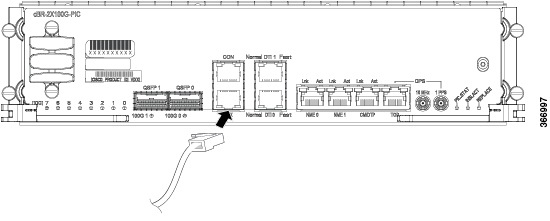 |
| Step 2 |
Connect the other end of the RJ-45 cable to the RJ-45-to-DB-9 adapter. |
| Step 3 |
Connect the RJ-45-to-DB-9 adapter to the appropriate serial port on the terminal server. |
What to do next
Cable Management for the Supervisor PIC in the Cisco cBR Chassis
The following accessories are used for routing the cables connected to the Supervisor PIC:
-
Supervisor PIC cable management bracket
-
Chassis-mounted cable strap-down clips
-
Chassis-mounted snap-on plastic fiber/cable routing guides
Use the upper cable management bracket and fiber/cable routing guides for routing the cables connected to the upper Supervisor PIC and the lower cable management bracket and fiber/cable routing guide for routing the cables connected to the lower Supervisor PIC.
The strap-down clips have multiple uses. They can be used:
-
to strap down cable bundles or conduit (there are multiple tie down points on each strap-down clip)
-
as a base for two snap-on plastic fiber/cable routing guides
Before you begin
-
Install the chassis-mounted cable strap-down clips and attach the snap-on plastic fiber/cable routing guides, as necessary based on the cable routing preference.
-
Connect the cables to the appropriate ports on the Supervisor PIC.
Required Tools and Equipment
-
Cable ties
Procedure
| Step 1 |
Perform the following for the fiber-optic cables connected to the Supervisor PIC:
The following figures illustrate the possible cable routing options for the fiber-optic cables connected to the Supervisor PIC: 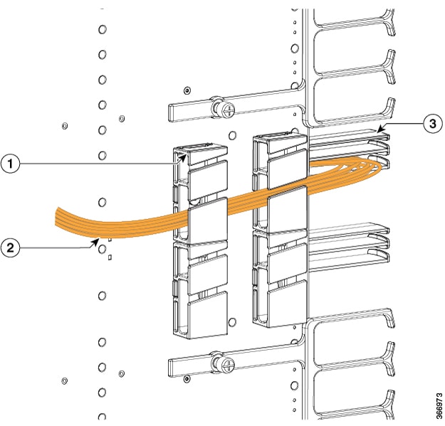
|
||||||||||||||||||||||||||||
| Step 2 |
Perform the following for the RJ-45 cables connected to the Supervisor PIC:
The following figures illustrate the possible cable routing options for the RJ-45 cables connected to the Supervisor PIC: 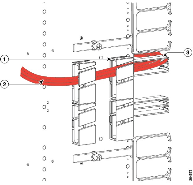
|
||||||||||||||||||||||||||||
| Step 3 |
Repeat Step 1 and Step 2 for the cables connected to the each Supervisor PIC. |
Using the USB Port on the Supervisor Card
Before you begin
Restrictions
The USB ports on the Supervisor Card are used for temporary connections. For all permanent connections, you must use the ports on the Supervisor PIC.
Required Tools and Equipment
-
Memory stick or flash drive
Procedure
| Step 1 |
Open the tethered I/O door on the Supervisor Card by pulling on the left edge of the door until the door is released from the spring-loaded ejector. 
|
||||
| Step 2 |
Connect the memory stick or flash drive to the USB port on the Supervisor Card. |
Using the Console Port on the Supervisor Card
Before you begin
Restrictions
-
When running a redundant configuration in the chassis, each Supervisor Card or Supervisor PIC must have a console port connection.
-
The console port on the Supervisor Card is for temporary connections. For permanent console connection, you must use the port on the Supervisor PIC.
Required Tools and Equipment
-
Console cable (with mini type-B USB connector on one end, and a type-A USB connector on the other end)
-
Exar XR21V1410 UART with USB interface
-
Cable with type-A USB connector on one end and DB-9 connector on the other end
-
PC or terminal
Procedure
| Step 1 |
Open the tethered I/O door on the Supervisor Card by pulling on the left edge of the door until the door is released from the spring-loaded ejector.
|
||||
| Step 2 |
Connect the mini type-B USB connector of the console cable to the console port on the Supervisor Card.
|
||||
| Step 3 |
Connect the type-A USB connector of the console cable to the Exar XR21V1410 UART with USB interface. |
||||
| Step 4 |
Connect the Exar XR21V1410 UART to the appropriate serial port on the PC or terminal using a cable with type-A USB connector on one end and DB-9 connector on the other end. |
||||
| Step 5 |
Power up the PC or terminal. |
||||
| Step 6 |
Configure the PC terminal emulation software or the terminal with the following settings:
|
Swap Supervisor 160G to Supervisor 250G 10GE Mode
Backup the Configuration and IOS Code
Procedure
| Step 1 |
Insert the Cisco certified eUSB disk into the USB0 on the active SUP160 board. |
|||||||||
| Step 2 |
Edit the configuration follow the steps below: Please note that on SUP250, all 10G and 100G interfaces are visible regardless of whether the related QSFP module is inserted or not. The backhaul interface numbering scheme on SUP250 is different from SUP160, shown as below:
Therefore, we recommend the user to copy the SUP160 configuration out to the server and edit the SUP160 configuration manually before copy back to the SUP250. |
|||||||||
| Step 3 |
Copy the sup250.txt into eUSB. |
|||||||||
| Step 4 |
Copy the IOS image into eUSB. |
|||||||||
| Step 5 |
Execute md5 check for IOS image. |
Swap the Supervisor
Procedure
| Step 1 |
Power off the cbr-8 chassis. |
| Step 2 |
Loosen the hook screw on the active SUP and pull out the SUP160 board from the chassis. |
| Step 3 |
Loosen the hook screw on the standby SUP and pull out the SUP160 board from the chassis. |
| Step 4 |
Label the cables connected to the active SUP PIC, then pull out all the cables from the SUP PIC. Loosen the hook screw on the active SUP PIC and pull out the SUP160 PIC from the chassis. |
| Step 5 |
Label the cables connected to the standby SUP PIC, then pull out all the cables from the SUP PIC. Loosen the hook screw on the standby SUP PIC and pull out the SUP160 PIC from the chassis. |
| Step 6 |
Insert the SUP250 board into the slot 4 on the rear side of the chassis and tighten the hook screw. |
| Step 7 |
Insert another SUP250 board into the slot 5 on the rear side of the chassis and tighten the hook screw. |
| Step 8 |
Insert the SUP250 PIC into the slot 4 on the front side of the chassis and tighten the hook screw. |
| Step 9 |
Insert another SUP250 PIC into the slot 5 on the front side of the chassis and tighten the hook screw. |
| Step 10 |
Insert the 1-to-4 breakout fibers into the QSFP module on SUP in slot 4 and slot 5 respectively. |
| Step 11 |
Connect all the cables into the new SUP250 PIC and SUP250 board on slot 4 and slot 5. |
| Step 12 |
Power on the chassis. |
| Step 13 |
Log in the active SUP via the active console port and log in the standby SUP via the standby console port, both boards should be in rommon mode. Send break and make sure the board is in rommon mode if it does not in rommon mode after boot up. |
| Step 14 |
Insert the eUSB into the USB0 of the SUP in slot4, boot the SUP from rommon to IOS. |
| Step 15 |
Once the SUP enter the IOS mode, copy the image from eUSB to bootflash on the SUP. |
| Step 16 |
Insert the eUSB into the USB0 of the SUP in slot 5, boot the SUP from rommon to IOS, Send break and make sure the board is in rommon mode if it does not in rommon mode after boot up. |
| Step 17 |
Once the SUP enter the IOS mode, and SUP redundancy reach SSO mode, On active SUP, copy the image from eUSB to bootflash on the standby SUP. |
| Step 18 |
Copy pre-saved running configuration from eUSB to nvram. |
| Step 19 |
Pull out the eUSB. |
| Step 20 |
Change the config-reg to 0x2102. |
| Step 21 |
Reload the system without saving the configuration on the active SUP. |
| Step 22 |
Once the system enter the IOS mode, verify SUP redundancy reach SSO via below show command: |
| Step 23 |
Verify the state of the 10GE backhaul interface links. If the 10GE backhaul interface links are administratively down, run
the |
| Step 24 |
Save the configuration by running the |
| Step 25 |
Save & backup current configuration. |
| Step 26 |
Copy the configuration into bootflash for backup. |
| Step 27 |
Check the WAN port connection by ping the peer device. |
| Step 28 |
Check the system health and service with the following commands: |
Upgrade Supervisor 160G to Supervisor 250G 100GE Mode
Backup the Configuration and IOS Code
Procedure
| Step 1 |
Insert the Cisco certified eUSB disk into the USB0 on the active SUP160 board. |
|||||||||
| Step 2 |
Edit the configuration follow the steps below: Please note that on SUP250, all 10G and 100G interfaces are visible regardless of whether the related QSFP module is inserted or not. The backhaul interface numbering scheme on SUP250 is different from SUP160, shown as below:
Therefore, we recommend the user to copy the SUP160 configuration out to the server and edit the SUP160 configuration manually before copy back to the SUP250. |
|||||||||
| Step 3 |
Copy the sup250.txt into eUSB. |
|||||||||
| Step 4 |
Copy the IOS image into eUSB. |
|||||||||
| Step 5 |
Execute md5 check for IOS image. |
Swap the Supervisor
Procedure
| Step 1 |
Power off the cbr-8 chassis. |
||
| Step 2 |
Loosen the hook screw on the active SUP and pull out the SUP160 board from the chassis. |
||
| Step 3 |
Loosen the hook screw on the standby SUP and pull out the SUP160 board from the chassis. |
||
| Step 4 |
Label the cables connected to the active SUP PIC, then pull out all the cables from the SUP PIC. Loosen the hook screw on the active SUP PIC and pull out the SUP160 PIC from the chassis. |
||
| Step 5 |
Label the cables connected to the standby SUP PIC, then pull out all the cables from the SUP PIC. Loosen the hook screw on the standby SUP PIC and pull out the SUP160 PIC from the chassis. |
||
| Step 6 |
Insert the SUP250 board into the slot 4 on the rear side of the chassis and tighten the hook screw. |
||
| Step 7 |
Insert another SUP250 board into the slot 5 on the rear side of the chassis and tighten the hook screw. |
||
| Step 8 |
Insert the SUP250 PIC into the slot 4 on the front side of the chassis and tighten the hook screw. |
||
| Step 9 |
Insert another SUP250 PIC into the slot 5 on the front side of the chassis and tighten the hook screw. |
||
| Step 10 |
Connect the 100G QSFP on SUP slot 4 and slot 5 respectively. |
||
| Step 11 |
Power on the chassis. |
||
| Step 12 |
Log in the active SUP via the active console port and log in the standby SUP via the standby console port, both boards should be in rommon mode. Send break and make sure the board is in rommon mode if it does not in rommon mode after boot up.
|
||
| Step 13 |
Insert the eUSB into the USB0 of the SUP in slot4, boot the SUP from rommon to IOS. |
||
| Step 14 |
Once the SUP enter the IOS mode, copy the image from eUSB to bootflash on the SUP. |
||
| Step 15 |
Insert the eUSB into the USB0 of the SUP in slot 5, boot the SUP from rommon to IOS, Send break and make sure the board is in rommon mode if it does not in rommon mode after boot up. |
||
| Step 16 |
Once the SUP enter the IOS mode, and SUP redundancy reach SSO mode, On active SUP, copy the image from eUSB to bootflash on the standby SUP. |
||
| Step 17 |
Copy pre-saved running configuration from eUSB to nvram. |
||
| Step 18 |
Pull out the eUSB. |
||
| Step 19 |
Change the config-reg to 0x2102. |
||
| Step 20 |
Reload the system without saving the configuration on the active SUP. |
||
| Step 21 |
Once the system enter the IOS mode, verify SUP redundancy reach SSO via below show command: |
||
| Step 22 |
Verify the state of the 100GE backhaul interface links. If the 100GE backhaul interface links are administratively down, run
the |
||
| Step 23 |
Save the configuration by running the |
||
| Step 24 |
Save & backup current configuration. |
||
| Step 25 |
Copy the configuration into bootflash for backup. |
||
| Step 26 |
Check the WAN port connection by ping the peer device. |
||
| Step 27 |
Check the system health and service with the following commands: |
 Feedback