Installing the Interface and PIC Cards in the Cisco cBR Chassis
 Note |
Any time a physical Online Insertion/Removal (OIR) is performed, the removed module must be left out 30-60 seconds before re-inserting it in the cBR-8 chassis. |
Installing the DOCSIS MAC/PHY Interface and PIC Card
Installing RF PIC in the Cisco cBR Chassis
 Warning |
If you are adding more interface line cards or upgrading the existing line cards, ensure that the power modules installed in the chassis are adequate to support the line cards. |
Perform this procedure to install the following PICs:
-
RF Through PIC
-
RF Protect PIC
-
RF PIC Blank card
To use the RF HA features, install the Protect PIC.
When HA must be configured, ensure that the Protect or Through PICs are installed in consecutive slots, with the Protect PIC being installed in the uppermost PIC slot.
 Caution |
Do not leave a PIC slot empty in order to avoid critical thermal alarms relating to overheating of individual components. Do not install any Blank PICs between any two Through PICs or between an Protect PIC and Through PIC. |
Before you begin
-
If high availability (HA) configuration is required, install an RF Protect PIC in the uppermost PIC slot.
-
Be aware of the weight and size of the equipment. Handle it with care.
-
Attach an ESD-preventive wrist strap to your wrist and connect the other end to the grounding lug connected to the chassis.
Required Tools and Equipment
-
ESD-preventive wrist strap
-
3/16" flat-blade torque screwdriver
-
RF Through PIC or RF Protect PIC or RF PIC Blank card
Procedure
| Step 1 |
Grasp the faceplate of the PIC with one hand and place your other hand under the PIC to support its weight. |
||||
| Step 2 |
Carefully align the PIC with the plastic guides in the slot. |
||||
| Step 3 |
Slide the PIC into the slot applying even pressure using both your hands until it is within an inch of full insertion. |
||||
| Step 4 |
Open the ejector levers on the PIC and fully insert the PIC into the slot applying even pressure on both sides until it mates with the midplane connectors.
|
||||
| Step 5 |
Simultaneously pivot both the ejector levers towards each other until they cannot be pivoted any further. |
||||
| Step 6 |
Tighten the two captive screws using a 3/16" flat-blade torque screwdriver with a torque of 6-8 lb-in (0.68 Nm to 0.90 Nm) to secure the PIC. |
What to do next
-
Install additional PIC.
-
If a card is not installed in the slot, install a blank filler card.
Using UCH.8 Connectors on the RF Through PIC
The faceplate of the RF Through PIC card has one downstream port cluster and two upstream port clusters. Three cable assemblies with UCH.8 connectors are used, one for each cluster, to connect the RF Through PIC.
Connect the cable assemblies in the following order:
-
Red cable assembly to the downstream port cluster.
-
One blue cable assembly to upstream port cluster with the ports US0 to US7.
-
Other blue cable assembly to upstream port cluster with the ports US8 to US15.
The following steps describe how to connect one UCH.8 connector. Repeat the procedure to connect all the three UCH.8 connectors.
Before you begin
-
Attach an ESD-preventive wrist strap to your wrist and connect the other end to the grounding lug connected to the chassis.
-
Install the chassis-mounted cable management bracket (if not already installed).
Required Tools and Equipment
- ESD-preventive wrist strap.
- 3/16" flat-blade torque screwdriver.
-
Cable Bundle containing the following cable assemblies:
-
One cable assembly with red colored cables connected to one UCH.8 connector.
-
Two cable assemblies with blue colored cables connected to one UCH.8 connector each.
-
Procedure
| Step 1 |
Align the small and large guide pins in the UCH.8 connector with the small and large guide pin holes on the PIC.
|
||||||||||||
| Step 2 |
Insert the guide pins of the UCH.8 connector into the guide pin holes in the PIC. |
||||||||||||
| Step 3 |
Hold the UCH.8 connector in place and tighten the lead screw using the 3/16" flat-head torque screwdriver, with a torque of 10-12 in-lbs. |
What to do next
Route the cable bundle through the corresponding slot in the RF cable management brackets attached to the side of the chassis.
After each UCH.8 connector has been installed on the RF Through PIC port, push the cable assembly into the corresponding cable management bracket attached to the side of the chassis.
Installing the DOCSIS MAC/PHY Interface Line Card in the Cisco cBR Chassis
Repeat this procedure for all the interface line cards and the line card blanks that you must install in the unused line card slots.
Warning |
If you are adding more interface line cards or upgrading the existing line cards, ensure that the power modules installed in the chassis are adequate to support the line cards. |
Before you begin
-
Attach an ESD-preventive wrist strap to your wrist and connect the other end to the grounding lug connected to the chassis.
-
Be aware of the weight and size of the equipment. Handle it with care.
Restrictions
-
Install the interface line card in the slot corresponding to the RF Protect or RF Through PIC installed.
Required Tools and Equipment
-
ESD-preventive wrist strap
-
3/16" flat-blade torque screwdriver
-
One of the following SSI Cards (line cards):
-
DOCSIS 3.0 MAC/PHY line card [PID: CBR-LC-8D30-16U30]
-
DOCSIS 3.1 MAC/PHY line card [PID: CBR-LC-8D31-16U31, or CBR-LC-4D31-16U31]
-
Line card blank. [PID: CBR-LC-BLANK]
-
Procedure
| Step 1 |
Loosen the captive screws on the appropriate slot using a 3/16" flat-blade torque screwdriver until the red bands are visible on the captive screws.
|
||
| Step 2 |
Pull the spring-loaded ejectors on the card until they release and are perpendicular to the faceplate. |
||
| Step 3 |
Grasp the faceplate of the card with one hand and place your other hand under the card to support its weight. |
||
| Step 4 |
Carefully align the support rails on the card with the rails in the appropriate slot. |
||
| Step 5 |
Slide and push the card into the slot applying even pressure using both your hands until it mates with its midplane connectors.
|
||
| Step 6 |
Simultaneously pivot both the spring-loaded ejectors towards the faceplate until they make contact with the faceplate. |
||
| Step 7 |
Tighten the two captive screws using a 3/16" flat-blade torque screwdriver with a torque of 10-12 lb-in (1.12-1.36 Nm) to secure the card. |
What to do next
A line card may be installed in the chassis during the OIR process for the following reasons:
-
As a replacement.
-
As an upgrade.
-
After the downstream or upstream PHY module was replaced or upgraded.
When a line card is installed in the chassis for any of the above-stated reasons, use the hw-module slot reload command to reload the line card.
Installing the DOCSIS MAC Interface and PIC Card
Installing Digital PIC in the Cisco cBR Chassis
Warning |
If you are adding more interface line cards or upgrading the existing line cards, ensure that the power modules installed in the chassis are adequate to support the line cards. |
Perform this procedure to install the following PICs:
-
Digital Through PIC
-
Digital PIC Blank card
Caution |
Do not leave a PIC slot empty in order to avoid critical thermal alarms relating to overheating of individual components. Do not install any Blank PICs between any two Through PICs. |
Before you begin
-
Be aware of the weight and size of the equipment. Handle it with care.
-
Attach an ESD-preventive wrist strap to your wrist and connect the other end to the grounding lug connected to the chassis.
Required Tools and Equipment
-
ESD-preventive wrist strap
-
3/16" flat-blade torque screwdriver
-
Digital Through PIC or Digital PIC Blank Card
Procedure
| Step 1 |
Grasp the faceplate of the PIC with one hand and place your other hand under the PIC to support its weight. |
||||
| Step 2 |
Carefully align the PIC with the plastic guides in the slot. |
||||
| Step 3 |
Slide the PIC into the slot applying even pressure using both your hands until it is within an inch of full insertion. |
||||
| Step 4 |
Open the ejector levers on the PIC and fully insert the PIC into the slot applying even pressure on both sides until it mates with the midplane connectors.
|
||||
| Step 5 |
Simultaneously pivot both the ejector levers towards each other until they cannot be pivoted any further. |
||||
| Step 6 |
Tighten the two captive screws using a 3/16" flat-blade torque screwdriver with a torque of 6-8 lb-in (0.68 Nm to 0.90 Nm) to secure the PIC. |
What to do next
-
Install additional PIC.
-
If a card is not installed in the slot, install a blank filler card.
Installing the DOCSIS MAC Interface Line Card in the Cisco cBR Chassis
Repeat this procedure for all the interface line cards and the line card blanks that you must install in the unused line card slots.
Warning |
If you are adding more interface line cards or upgrading the existing line cards, ensure that the power modules installed in the chassis are adequate to support the line cards. |
Before you begin
-
Attach an ESD-preventive wrist strap to your wrist and connect the other end to the grounding lug connected to the chassis.
-
Be aware of the weight and size of the equipment. Handle it with care.
Restrictions
-
Install the interface line card in the slot corresponding to the Digital Protect or Digital Through PIC installed.
Required Tools and Equipment
-
ESD-preventive wrist strap
-
3/16" flat-blade torque screwdriver
-
One of the following SSI Cards (line cards):
-
DOCSIS MAC line card (40G) [PID: CBR-CCAP-LC-40G]
-
DOCSIS MAC line card (80G) [PID: CBR-CCAP-LC-G2-R]
-
Line card blank. [PID: CBR-LC-BLANK]
-
Procedure
| Step 1 |
Loosen the captive screws on the appropriate slot using a 3/16" flat-blade torque screwdriver until the red bands are visible on the captive screws.
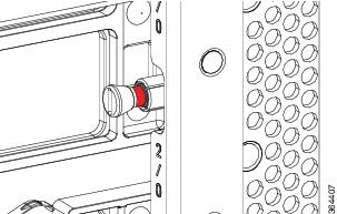 |
||
| Step 2 |
Pull the spring-loaded ejectors on the card until they release and are perpendicular to the faceplate.  |
||
| Step 3 |
Grasp the faceplate of the card with one hand and place your other hand under the card to support its weight. |
||
| Step 4 |
Carefully align the support rails on the card with the rails in the appropriate slot. |
||
| Step 5 |
Slide and push the card into the slot applying even pressure using both your hands until it mates with its midplane connectors.
 |
||
| Step 6 |
Simultaneously pivot both the spring-loaded ejectors towards the faceplate until they make contact with the faceplate.   |
||
| Step 7 |
Tighten the two captive screws using a 3/16" flat-blade torque screwdriver with a torque of 10-12 lb-in (1.12-1.36 Nm) to secure the card. |
What to do next
A line card may be installed in the chassis during the OIR process for the following reasons:
-
As a replacement.
-
As an upgrade.
-
After the downstream or upstream PHY module was replaced or upgraded.
When a line card is installed in the chassis for any of the above-stated reasons, use the hw-module slot reload command to reload the line card.
 Feedback