Field Area Routers (FARs)
Field Area Routers are core components of a Field Area Network that provide connectivity between field devices, such as meters, sensors, and control equipment, and the head-end routers.
Cisco Iot FND enables you to,
-
manage the FAR lifecycle,
-
perform configuration and maintenance activities, and
-
monitor and troubleshoot router performance.
Supported Field Area Routers
Cisco IoT FND supports the following Field Area Routers:
-
Cisco Catalyst IR1800 Rugged Series Routers
-
Cisco Catalyst IR8100 Heavy-Duty Series Routers (IR8140)
-
Cisco Catalyst IR1100 Rugged Series Routers (IR1101)
-
Cisco 1000 Series Connected Grid Routers (CGR1120 and CGR1240)
-
Cisco 800 Series Industrial Integrated Services Routers (IR800)
-
Cisco 800 Series Routers
Cisco also identifies Cisco 800 Series Access Points (AP800) as supported when integrated with C800 and IR829 devices.
Add router device files
Use the Device File Management page to manage router device files within the application.
Procedure
|
Step 1 |
Navigate to . |
|
Step 2 |
Select to open the Upload File to Routers page. |
|
Step 3 |
Search for the router device file using the full name or an abbreviated string.
|
|
Step 4 |
Select the routers for the upload. The system displays the number of router files available based on your search criteria, with all routers selected by default. You can adjust the display count using the drop-down menu (options: 10, 50, 100, 200) and clear the check boxes for any routers you do not want to include. |
|
Step 5 |
Click Upload . |
Delete files from routers
Follow these steps to remove files from routers:
Procedure
|
Step 1 |
From the main menubar, choose . |
||
|
Step 2 |
From the left pane, select the file that you want to delete. |
||
|
Step 3 |
On the Actions tab, click Delete . The Delete file from List dialog box appears. |
||
|
Step 4 |
Select a file to delete. You can delete the file from all routers in the selected group or any subset of routers in the group. |
||
|
Step 5 |
Click Delete File . The Delete File from Routers dialog box displays. |
||
|
Step 6 |
Check the check boxes of the routers from which you want to delete the file.
|
||
|
Step 7 |
Click Delete . If there are no file transfer or deletion, configuration push, firmware upload, or install or reprovision operations in progress for the group, the delete operation begins. Cisco IoT FNDsearches the.../managed/files/ directory on the devices for the specified file name.
You can select another group and file to perform a separate file deletion while file transfer or deletion processes are in progress for this group. When you cancel file deletion process before it completes, the currently running file deletion process completes and all waiting file deletion processes are cancelled. File operations status, progress percentage, and any error messages are displayed in the job status area. |
Structure of router import records in Notice-of-Shipment XML files
This reference provides the structure of the <R> record used for importing router configurations into Cisco IoT FND.
You use the Notice-of-Shipment XML file sent to you by your Cisco partner. This file contains an <R> record for every router shipped to you. This is an example of an <R> record for a CGR:
<AMI>
<Re1ays>
<DCG deviceC1ass=?10.84.82.56?>
<PID>CGR1240/K9</PID>
<R>
<ESN>2.16.840.1.114416.3.2286.333498</ESN>
<SN>FIXT:SG-SALTA-10</SN>
<wifiSsid>wifi ssid 1</wifiSsid>
<wifiPsk>wifi psk 1</wifiPsk>
<adminPassword>ppswd 1</adminPassword>
<type6PasswordMasterKey>secret 1</type6PasswordMasterKey>
<tunne1SrcInterface1>Ethernet2/3</tunnelSrcInterface1>
</R>
</DCG>
</Re1ays>
</AMI> Note |
For a list of all Device Properties that you can configure using the XML configuration template, refer to Device Properties . |
| Field | Description | ||
|---|---|---|---|
|
PID |
The product ID, as supplied by Cisco. This is not printed on the product. |
||
|
SN |
The router serial number.
|
||
|
ESN |
A serial number assigned by your Cisco partner to the WPAN mesh card inside the router. This field is not used by Cisco IoT FND. |
||
|
wifiSsid |
This information is configured on the router by your Cisco partner during the manufacturing configuration process. Cisco IoT FND stores this information in its database for future use. |
||
|
wifiPsk |
|||
|
adminPassword |
|||
|
adminUsername |
|||
|
type6PasswordMasterKey |
|||
|
tunnelSrcInterface1 |
View router details
Enable network administrators to access, monitor, and review router information through the Field Devices page.
You use the Field Devices page to view network devices for monitoring and configuration. By default, devices are shown in the Default view.
Procedure
|
Step 1 |
Navigate to . |
|
Step 2 |
Under Browse Devices pane, review the listed network devices available for monitoring or configuration. The Field Devices page displays devices in the Default view by default. |
View router device properties
The Field Devices page defaults to the List view, which contains basic device properties, unless you select the Default to map view option in user preferences.
Procedure
|
Step 1 |
Select a router or group of routers in the Browse Devices pane. |
|
Step 2 |
Click the desired tab in the main pane to view specific device properties. Each tab displays different sets of device properties. For example, the Default view displays basic device properties, while the Cellular-GSM view displays properties specific to the cellular network. |
What to do next
For information on customizing router views, see Customize device views . For details on device properties, see Device Properties . For common actions such as adding labels, see Common device operations .
View routers in map view
Before you begin
Access the User Preferences page to enable the map feature.
Procedure
|
Step 1 |
Select the root or user name at the top, upper-right-hand corner of the screen and click Preferences . |
||
|
Step 2 |
Select the Enable map checkbox.
|
||
|
Step 3 |
Navigate to , choose the router, and click Map . |
The RPL tree connection displays data traffic flow as blue or orange lines:
-
Orange lines indicate that the link is an uplink: data traffic flows in the up direction on the map.
-
Blue lines indicate that the link is a downlink: data traffic flows in the down direction on the map.
Note |
You can view any RPL tree by clicking the device in Map view, and closing the information pop-up window. |
View router usage statistics
From Cisco IoT FND release 4.11 onwards, the Device Details page provides a new Router Usage Stats chart for the Cisco IOS (CGR1000 and IR800) and IOS-XE (IR1101, IR8100, IR1800) devices. This chart displays the historical trend of the CPU, memory, and disk usage on an hourly (6 hours), daily (one day), weekly (one week), and monthly (four weeks) basis. You can also visualize the time-specific data by customizing the date and time. However, the maximum date range that you can define is limited to the data retention period specified in the UI ( refer to Configure data rention ). The data retention period that you can set ranges from a minimum of one to a maximum of 90 days.
For more information, see Set time filters to view charts .
Procedure
|
Step 1 |
Choose . |
|
Step 2 |
Select the device type. The Inventory tab displays the devices for the selected device type. You can also filter the usage data based on CPU, memory, or disk. |
|
Step 3 |
Click the required device on the right pane to view the Router Usage Stats chart for the selected device. |
IOS-XE command execution in Cisco IoT FND UI
The IOS-XE command option in Cisco IoT FND is a Troubleshoot tab capability for running supported IOS-XE EXEC commands from the device details page during troubleshooting. This feature provides a controlled user-interface path for operational command execution, which can be used for Cisco IOS-XE device troubleshooting through the Cisco IoT FND user interface.
Role in device troubleshooting
The command option extends the device details workflow by letting users collect command output without leaving the Cisco IoT FND and logging into the device CLI.
Supported platforms
The IOS-XE command option is supported for these Cisco IOS-XE devices:
-
IR8140
-
IR1800
-
IR1100
-
IR1000
Command processing model
Cisco IoT FND validates command input before execution and sends accepted commands to the device. The UI returns the device output or an applicable error response after execution.
|
Release information |
Feature name |
Description |
|---|---|---|
|
Cisco IoT FND Release 26.2.1 |
IOS-XE Exec command execution support in FND UI |
Adds an IOS-XE command option to the device details Troubleshoot tab in Cisco IoT FND. |
Use the Troubleshoot tab to execute IOS-XE commands
Use the Troubleshoot tab on a supported device details page to execute safe IOS-XE commands from the Cisco IoT FND user interface. The command output appears in the Response area.
Note |
Use this tab only for supported operational commands that do not change device configuration or introduce security risks. |
The Troubleshoot tab is available for supported Cisco IOS-XE devices, including IR8140, IR1800, IR1100, and IR1000.
Before you begin
-
Ensure that your user role has the Execute IOS-XE Commands permission.
Note
To grant the Execute IOS-XE Commands permission without modifying the base role, create a custom role that incorporates all existing permissions and the troubleshooting permission, and assign it exclusively to the users who need it. For instructions on creating and assigning a custom user role, refer Custom User Roles.
-
The selected device is a supported Cisco IOS-XE device and is not in the unmanaged, out of service, or unheard state.
-
No active firmware upload or upgrade is running for the selected device. You cannot execute commands while a firmware upload or upgrade is active.
Procedure
|
Step 1 |
Choose , and in the Browse Devices pane, select the supported IOS-XE router device type. The Field Devices page lists routers, endpoints, and gateways in the Browse Devices pane. |
||
|
Step 2 |
Click the name of the device that you want to troubleshoot. The device details page opens for the selected device. |
||
|
Step 3 |
Click the Troubleshoot tab. The tab is not visible for unsupported devices or for devices in the unmanaged, out of service, or unheard state. The feature supports device states such as registration and bootstrap. |
||
|
Step 4 |
Click the information icon to review the supported command rules. The information icon shows the supported commands, supported special characters, allowed characters, and disallowed characters. Cisco IoT FND validates commands in the UI and backend. |
||
|
Step 5 |
In the Command field, enter a supported IOS-XE EXEC command or select a previously executed command from the drop-down list. The command field uses show version as the placeholder example. Cisco IoT FND supports safe abbreviations, such as sh, tr, and tracert, when the abbreviations match the supported command rules. Commands are limited to 200 characters. You can enter up to five supported commands with semicolons.
|
||
|
Step 6 |
In the Timeout (sec) field, keep the default timeout value or enter a longer timeout value. |
||
|
Step 7 |
Click Execute. Command execution occurs in the background. You can navigate to other screens while the command runs. The Response area shows command execution progress while the command is running. |
||
|
Step 8 |
Review the command output in the Response area. The Response area expands with vertical and horizontal scroll bars for long command output. If a network-related error occurs, Cisco IoT FND displays the applicable error popup. Network-related errors include device unreachable, connection timeout, network cable unplugged, device rebooting, and WSMA service downtime. You can use the Clear Responses button to clear the Response text field. |
||
|
Step 9 |
(Optional) To export the command-history records of the device, |
Cisco IoT FND displays the IOS-XE command output or applicable error response and records the command execution in the audit log with the user identity, command, and execution timestamp.
Filter routers using built-in filters
You can refine the list of displayed routers by using the built-in router filters such as Up, Down, or Unheard status available under ROUTERS in the Browse Devices pane. You can also use the saved custom searches in the Quick View pane.
Procedure
|
Step 1 |
From the main menu, choose |
|
Step 2 |
In the Browse Devices pane, locate ROUTERS. You can also apply the saved custom seaches from the Quick View tab. |
|
Step 3 |
Under status, select the desired filter (for example, Up, Down, Unheard) to apply it. The list updates to show routers matching the selected status in the right pane. Selecting a filter inserts a corresponding search string (e.g., status:up) into the Search field automatically. For example, clicking the Up filter under ROUTERS inserts the search string status:up. To filter routers by system security mode, use the System Security Mode filter or enter a search string such as systemSecurityMode:secure. You can also use the saved custom searches from the Quick View pane to apply frequently-used filters. |
View router configuration groups
Use the Browse Devices pane to display routers that belong to one of the groups (such as CGR1000) listed under ROUTER.
Procedure
|
Step 1 |
Navigate to the page. |
|
Step 2 |
From the Browse Devices pane, select the desired group listed under ROUTER to display the associated routers. |
View router firmware groups
Follow these steps to verify available firmware images for router groups:
Procedure
|
Step 1 |
Choose . |
|
Step 2 |
From the left pane, click the Groups tab and choose the desired router group (for example, Default-cgr1000, Default-ir1100, Default-ir800 or ). |
|
Step 3 |
Review the firmware images displayed under the Name field for each selected router group. |
View router tunnel groups devices
A router tunnel group is used to organize and manage router devices within the network infrastructure. Viewing these associations helps streamline device management and troubleshooting.
Follow these steps to view router devices assigned to tunnel groups:
Procedure
|
Step 1 |
From the main menu, choose . |
|
Step 2 |
Locate and select the desired router tunnel group under the ROUTER listing. |
|
Step 3 |
Review the list of router devices associated with the selected tunnel group. |
Export mesh routing tree data
Export mesh routing tree data for a selected router, including the parent-child node hierarchy, to an Excel (.xlsx) file.
Cisco IoT FND exports routing information for the parent node (router) and its associated child nodes (meters) from the Mesh Routing Tree tab. The Excel (.xlsx) file captures the multihop parent-child hierarchy in separate sheets for each hop level. By default, each sheet displays the parent nodes for that hop level. Expand or collapse the rows to view the parent-child relationships.
Before you begin
-
This export option is available only for routers, not for other device categories such as endpoints.
-
Ensure that your environment supports Microsoft Excel files and has sufficient storage for the exported file.
Follow these steps to export mesh routing tree data:
Procedure
|
Step 1 |
Choose . |
|
Step 2 |
Click the device for which you want to export routing tree data. The Device Info page appears. |
|
Step 3 |
Click the Mesh Routing Tree tab. |
|
Step 4 |
Click Export Routing Tree. The Excel file is saved to the file system with the following name: The exported data captures the relationships between the root node and its associated child nodes. The first sheet is named Root. Subsequent sheets are named Hop-level-<hop number>, such as Hop-level-1 and Hop-level-2. Starting with Cisco IoT FND Release 26.2.1, when location information is available, the exported file includes the latitude and longitude coordinates of each device.
For Cisco IR8100 routers, the exported routing tree data is based on the selected WPAN interface. |
Router push configuration count
The router push configuration count is a system parameter that limits the volume of concurrent configuration updates sent to network devices.
-
Controls the rate of configuration delivery.
-
Prevents device overload during mass updates.
-
Ensures sequential processing of network changes.
Router Push Configuration Count management
Manage and track the number of configuration changes applied to a group of routers during the configuration push using Cisco IoT FND.
|
Feature Name |
Release |
Description |
|---|---|---|
|
Manage Router Push Configuration Count |
Cisco IoT FND Release 5.0 |
Define the number of router configuration changes or updates that you want to apply to routers within a specific group, simultaneously. Manage and track the number of configuration changes applied to a group of routers during the configuration push using Cisco IoT FND. |
Router Push Configuration Count Per Group value
The Router Push Configuration Count Per Group is a configuration parameter that determines the maximum number of parallel router push operations allowed within a group.
-
The default value is 5.
-
The maximum permissible value is 100.
-
The configuration value applies globally to all router push configurations.
Note |
Define the Router Push Configuration Count Per Group value globally to all router push configurations using Cisco IoT FND. The maximum parallel or concurrent router push configuration count is applied to all the group of routers. |
Benefits of managing router push configuration count
This reference outlines the operational advantages of using the router push configuration count feature to optimize network management and minimize manual configuration risks.
The following benefits are associated with managing router push configuration counts:
-
Adaptability: You can quickly adapt configuration counts to meet changing network requirements, enhancing overall network management.
-
Error Reduction: The Router Push Configuration Count Per Group field minimizes the risk of errors that might occur with manual file edits.
Configure router push configuration count
Procedure
|
Step 1 |
From the main menu, choose . |
|
Step 2 |
Enter the number of router push configurations to be pushed to a group in the Router Push Configuration Count Per Group field. The maximum number of router push configurations you can enter is 16. |
|
Step 3 |
Click Save. The router push configuration count is set. |
Push configurations to routers
Use this task to push configuration to routers.
Router configuration pushes are performed from the Push Configuration tab for selected router groups or subsets.
Note |
CGRs, IR800s, and ISR 800s can coexist on a network; however, you must create custom configuration templates that include the router types. |
Procedure
|
Step 1 |
Choose . |
|||||||
|
Step 2 |
Select the group or subset of a group to push the configuration to the Configuration Groups pane. |
|||||||
|
Step 3 |
Click the Push Configuration tab to display that window. |
|||||||
|
Step 4 |
In the Select Operation drop-down list, choose Push ROUTER Configuration. For IR800 groups with embedded AP devices, choose Push AP Configuration to push the AP configuration template. If the router configuration contains a deprecated insecure CLI command and the target router is in secure mode, Cisco IoT FND moves the router to insecure mode before applying the configuration. |
|||||||
|
Step 5 |
In the Select Operation drop-down list, choose Push ENDPOINT Configuration . |
|||||||
|
Step 6 |
Click Start. The Push Configuration page displays the status of the push operation for every device in the group. If an error occurs while pushing configuration to a device, the error and its details display in the relevant columns. If a push operation includes deprecated insecure CLI commands, review the warning or error message details in the device status table after the operation completes. In the Status column, one of these values appears:
|
What to do next
Note |
To refresh the status information, click the Refresh button. |
Note |
After deprecated insecure CLI commands are removed from the template and router configuration, use the Move to Secure Mode operation on the Push Configuration tab to move the router back to secure mode. |
Enable SD card password protection
Use this task to enable CGR SD card password protection.
Password protection for the SD card in the CGR helps prevent unauthorized access and prevents transference of the CGR SD card to another system with a different password.
The Device Info pane displays CGR SD card password protection status in the Inventory section. The Config Properties tab displays the SD card password in the Router Credentials section.
Before you begin
Note |
This does not apply to IR800s. |
Procedure
|
Step 1 |
Choose . |
|||
|
Step 2 |
Select the CGR group or CGRs to push the configuration to in the Configuration Groups pane |
|||
|
Step 3 |
Select the Push Configuration tab. |
|||
|
Step 4 |
In the Select Operation drop-down menu, choose Push SD Card Password |
|||
|
Step 5 |
Click Start. Click Yes to confirm action or No to stop action. |
|||
|
Step 6 |
Select . |
|||
|
Step 7 |
Select the desired protection method:
|
|||
|
Step 8 |
Click Push SD Card Password. |
Replace routers in Cisco IoT FND
Before you begin
Before proceeding with a Return Material Authorization (RMA) for any device integrated with Cisco IoT FND that you want to replace, perform these steps:
Procedure
|
Step 1 |
Perform a backup of the configuration from the router that you want to replace. |
|
Step 2 |
Install the new router in the same location as the router that you want to replace. |
|
Step 3 |
Before connecting the new device to the network, restore the configuration from the backup device. |
|
Step 4 |
Verify if the new router that you are adding as a replacement is functioning as expected while it is connected to the network. |
What to do next
Note |
For more details on how to add new FAR devices and routers, see Managing Devices . |
Improved Audit Trail
The Improved Audit Trail is a security feature that enables the systematic tracking and extraction of user and system events.
-
Supports CSV format for external analysis.
-
Maintains detailed event timestamps and user identifiers.
-
Facilitates automated log retention and archival.
CSV file download for audit trail
Provides access to .CSV files used for adding, removing, or editing devices within Cisco IoT FND to maintain an accurate audit trail.
|
Feature Name |
Release |
Description |
|---|---|---|
|
Improved Audit Trail |
Cisco IoT FND Release 5.0 |
When you add, remove, or edit files using .CSV files on Cisco IoT FND, a log is generated in the Audit Trail page. You can download the .CSV file that you used to change the devices. |
Information about improved Audit Trail
The enhanced Audit Trail page provides direct access to .csv files for device actions performed in Cisco IoT FND Release 5.0 and later.
-
Provides direct download links for .csv files.
-
Supports tracking of changes made through .csv file uploads.
-
Includes logs for actions performed via NBAPIs.
Note |
Download the .CSV file logs even when you use NBAPIs for your device actions. |
Benefits of improved audit trail
This reference outlines the advantages of the improved audit trail, specifically focusing on transparency, accountability, and simplified record management through .csv file downloads.
-
Gain immediate access to detailed records of device management actions, allowing for clear and transparent auditing of changes made via .csv files. This helps maintain accountability and ensures compliance with organizational policies.
-
Downloading and storing the .csv files directly from the audit trail simplifies record-keeping practices.
Download CSV files from audit trail
You can download audit trail CSV files from the Cisco IoT FND system management interface.
Procedure
|
Step 1 |
From the Cisco IoT FND menu bar, choose . |
|
Step 2 |
Locate a log entry for Devices added , Changed Device Properties , or Devices removed in the audit trail list. |
|
Step 3 |
In the Details column, find the clicable CSV link. |
|
Step 4 |
Click the CSV file to download the file. The CSV file contains information such as the timestamp, user ID, and device details. |
Router admin password rotation in Cisco IoT FND
Cisco IoT FND supports router administrator password rotation for supported Cisco IOS and Cisco IOS XE devices. The feature uses the rotate_admin_password.sh script in the Cisco IoT FND cgms tools package and a CSV file that maps device identifiers to administrator passwords. This script is either run manually
or scheduled using a cron job
The cgms tools package can be installed on a Cisco FND Oracle Bare Metal, a Postgres VM, or a separate VM. FND installation is not required on the separate VM. For information on installing cgms tools on a separate VM, see Install CGMS Tools RPM on a separate VM .
The following topics describe supported platforms, CSV file requirements, manual password rotation, and scheduled password rotation.
|
Feature |
Release |
Description |
|---|---|---|
|
Admin Password Rotation |
Cisco IoT FND Release 5.0 |
The Cisco IoT FND tools package includes the rotate_admin_password.sh script with CSV input to rotate administrator passwords across Cisco IoT FND devices that use Cisco IOS or Cisco IOS XE. |
Supported platforms
This reference lists the supported Cisco IOS and Cisco IOS-XE device types for the current environment.
The supported device types are:
-
Cisco IOS Device Types: CGR1000 and IR800
-
Cisco IOS-XE Device Types: IR8100, IR1800, and IR1100
Prerequisites
Complete the following prerequisites before executing the rotate_admin_password script:
-
Password preference synchronization in the command.txt file and the device configuration.
-
Define parameters in the CSV File .
-
Ensure that routers are in Up state.
-
No active operation such as config push, firmware upgrade should be running in Cisco IoT FND.
Deployment Configuration
Based on the deployment type, copy the required files to the cgms-tools package.
-
Oracle Bare Metal Deployment
Filename
Copy From
Copy To
.fnd_psk_enc
/opt/cgms/server/cgms/conf/.fnd_psk_enc
/opt/cgms-tools/conf
fnd_psk.keystore
/opt/cgms/server/cgms/conf/fnd_psk.keystore
/opt/cgms-tools/conf
jdbc.properties
/opt/cgms/tools/conf/jdbc.properties
/opt/cgms-tools/conf/jdbc.properties
cgms_keystore
/opt/cgms/server/cgms/conf/cgms_keystore
/opt/cgms-tools/conf
cgms.properties
/opt/cgms/server/cgms/conf/cgms.properties
/opt/cgms-tools/conf
-
Postgres Virtual Machine Deployment
Copy From
Copy To
docker cp fnd-container:/opt/cgms/server/cgms/conf/.fnd_psk_enc /opt/cgms-tools/conf
/opt/cgms-tools/conf
docker cp fnd-container:/opt/cgms/server/cgms/conf/fnd_psk.keystore
/opt/cgms-tools/conf
docker cp fnd-container:/opt/cgms/tools/conf/jdbc.properties
/opt/cgms-tools/conf/jdbc.properties
docker cp fnd-container:/opt/cgms/server/cgms/conf/cgms_keystore
/opt/cgms-tools/conf
docker cp fnd-container:/opt/cgms/server/cgms/conf/cgms.properties
/opt/cgms-tools/conf
Password preference synchronization
Password preference synchronization is the process of matching the device-level password type with the corresponding command defined in the command.txt file.
-
Device configuration must match the command.txt entry.
-
Plaintext configurations require the password command.
-
Encrypted configurations require the secret command.
-
Router password configuration: The router is configured with either plaintext or secret password.
-
Command.txt file: The command.txt file has two commands, namely "password" and "secret" as shown below. Based on the password configured in the device (plaintext or secret), provide the command (password or secret) in the command.txt file.
username {username} privilege 15 password {password}
username {username} privilege 15 secret {password}
Password combinations for synchronization
The table lists the allowed password combinations for a successful admin password rotation.
|
Device Configuration |
Command.txt |
|---|---|
|
Plaintext |
Password (plaintext) |
|
Encrypted |
Secret |
Attention |
The admin password rotation fails if there is a password preference mismatch in the command.txt and the router configuration. The following table lists the password preference combinations that are not supported.
|
CSV File
The CSV file is a configuration input that maps device identifiers to their respective admin passwords for the rotation process.
The rotate_admin_password script is executed based on the information you provide in the CSV file, which contains the device EID and the password.
The CSV file requires the following information for device password rotation:
-
EID: The EID can either be router-specific or HER-specific. If you provide the HER EID, the admin password is rotated for all the routers that are associated with the HER. If you provide the router-specific EID, the admin password is rotated for that specific router.
-
Password : Cisco IoT FND provides options for plaintext, encrypted, or blank password fields in the CSV file.
CSV File Configuration Details
The CSV file serves as a configuration input that maps device identifiers to their respective admin passwords for the rotation process.
The following table outlines the password options available for the CSV file:
Plaintext Password
In the CSV file, provide a password that is a combination of uppercase (A-Z), lowercase (a-z), numbers (0-9), and special character ( !@#$%^&*.).
Sample CSV file for routers :
EID,ADMINPASSWORD
IR1101-K9+FCW2226006G,cisco123!
IR1101-K9+FCW2226004G,Cisco123
IR8140H-P-K9+FDO2J46Z,pdsL$123
Encrypted Password
If you want to encrypt the admin password, use the signature tool.
Sample CSV file for routers :
In the following example, the plaintext password is encrypted using the signature tool.
[root@iot-tps bin]# cat Single_Device_encrypted.csv
EID,ADMINPASSWORD
IR1831-K9+FCW2729Y2QV,VAXKhqI03xomp40f9xdyhIqYl4hh+6pztOAsRGwhrFUjD0xp+
F7zrIJUWOHpBiGC7yVIsqZyb70AEPuLVuZXGFLU/gQ9wpDSkoBNLVyxBYkSABD5vBG5Z2OS
TtaSva3xjnR9kGnw2P30nXSxEB2PNYHjpi8NVQLEiAz8JwVWLePt2xs6v+kXmsKYFrxZE6e2
Q5Mi9z+FW5COSiDLpt1//aLHIQIzR3QHgsiCi0RG/dVxvBn4Ra6NdYBqAsl17GVcFyvkSJhNs
KyeW0bPvuDpAAgRiga2i3rlJ5m0im/eT513aQWJXjHOotJmU/6sZ4jDzWQKop96modyEYuzrvNQrg==
Blank
If the admin password field is blank in the CSV file, the password is autogenerated.
Sample CSV file for routers :
EID,ADMINPASSWORD
IR1101-K9+FCW2226005G
Sample CSV file for HERs :
HEREID,ADMINPASSWORD
CSR1000V+9J04F38WNBP
Note |
|
Customize parallel administrator password updates
By default, you can update passwords on up to 20 routers in parallel. You can customize the default value of 20 based on your deployment needs.
Procedure
|
Step 1 |
Locate the configuration file at /opt/cgms-tools/conf/rotate-admin-password.properties. |
|
Step 2 |
Edit the |
|
Step 3 |
Locate the |
|
Step 4 |
Change the value to the desired number of threads. Example: |
Configure the generated password length for router admin rotation
Use the rotate-admin-password properties file to set the length of passwords that Cisco IoT FND generates. The default generated password length is 15 characters.
Cisco IoT FND creates a password automatically when the ADMINPASSWORD field in the CSV file is blank for router-specific rotation or during HER-level password rotation. You can configure the auto-generated password length during password rotation.
Follow these steps to configure the generated password length for router admin rotation.
Procedure
|
Step 1 |
Open the configuration file located at /opt/cgms-tools/conf/rotate-admin-password.properties using a text editor. |
|
Step 2 |
Locate the The default password length is 15. |
|
Step 3 |
Change the value of Example:The maximum password length is 100 characters. |
|
Step 4 |
Save the rotate-admin-password.properties file. |
|
Step 5 |
Run the rotate_admin_password.sh script, providing the required CSV file as input. In the CSV file, keep the ADMINPASSWORD field blank to have Cisco IoT FND generate the router administrator password during password rotation. |
Cisco IoT FND uses the length you specified for automatically generated router administrator passwords during password rotation.
Update administrator passwords on multiple routers
The rotate_admin_password.sh script is available with the cgms tools package in the Cisco IoT FND bundle OVA/rpm at /opt/cgms-tools/bin/rotate_admin_password.sh. It supports Cisco IOS and Cisco IOS XE device types.
Procedure
|
Step 1 |
Specify the password rotation details in the CSV file. For router-specific rotation, specify the router EID and the password in the CSV file. The password can be plaintext, secret, or system generated. For HER level rotation, specify the HER in the CSV file. The password is system-generated and rotated for all devices that tunnel with the specified HER. |
||
|
Step 2 |
Run the rotate_admin_password.sh script with the CSV file. Example:
|
Success case:
[root@iot-fnd log]# cat rotate_admin_password_status_1750360977943.csv
                "EID","MESSAGE","STATUS"
                "IR1831-K9+FCW2729Y2QL",
                "Successfully updated the admin password.
                The new password is <rotated password>","SUCCESS"
Failure case:
[root@iot-fnd-oracle log]# cat rotate_admin_password_status_1749039357401.csv
                "EID","MESSAGE","STATUS"
                "IR1101-K9+FCW2708YA7X","'adminPassword' length must be greater than or equal to 3,
                'adminPassword' must contain at least 3 out of 4 types: uppercase, lowercase, numbers,
                permitted special characters !""#$%&'()*+,-./:;<=>@[]^_`{|}~","FAILURE"
Rotate the router admin password manually
Use this task to rotate the router admin password manually.
Manual password rotation uses the router admin password rotation script and a CSV file that lists EIDs and admin passwords.
Before you begin
Completing the Prerequisites is a must.
Procedure
|
Step 1 |
Run the script to change the password for the router admin. The CSV file contains the list of EIDs and admin passwords. For more information, see CSV File. |
|
Step 2 |
On successful execution of the script, disconnect and reconnect to the router with the new password. |
What to do next
Upon successful script execution, verify if the operations such as refresh metrics, config push, firmware upgrade are working fine in FND.
Schedule admin password rotation with CronJob
This topic provides guidance on scheduling the rotate_admin_password script as a cron job during monthly maintenance windows. We recommend scheduling the cron job during the monthly maintenance window to avoid conflicts with the active operations in Cisco IoT FND. For example, schedule the script to run at 12:00 AM on the first day of every month.
The script automation is supported for these deployments:
Note |
For a successful password rotation, it is recommended to allow a 24-hour gap between each script execution. |
Schedule Oracle bare metal deployment
Use this task to schedule admin password rotation for Oracle bare metal deployment.
Oracle bare metal deployments use a crontab entry to run the router admin password rotation script on a schedule.
Before you begin
Complete the Prerequisites before scheduling admin password rotation.
Procedure
|
Oracle Bare Metal Deployment: Run the script to schedule for the password rotation.
|
What to do next
Upon successful script execution, verify if the operations such as refresh metrics, config push, firmware upgrade are working fine in Cisco IoT FND.
Schedule Postgres VM deployment
Use this task to schedule admin password rotation for Postgres VM deployment.
Postgres VM deployments require the CGMS Tools RPM, database access in pg_hba.conf, and cron scheduling for password rotation.
Before you begin
Complete the Prerequisites before scheduling admin password rotation.
Procedure
|
Step 1 |
Install or upgrade the tools rpm in VM. |
|
Step 2 |
Enable the db connection in pg_hba.conf with the following entry. Example:203.0.113.10/32
|
|
Step 3 |
Restart postgresql. |
|
Step 4 |
Copy the following files from the docker container to the cgms-tools package.
|
|
Step 5 |
Provide Postgres IP in the jdbc.properties as below. |
|
Step 6 |
Add the route in the server for the device reachability. Also, make sure the devices are reachable from the VM. |
What to do next
After the script executes successfully, verify if the operations such as refresh metrics, config push, firmware upgrade are working fine in Cisco IoT FND.
Cisco IoT FND WPAN
Cisco Wireless Personal Area Network (WPAN) is a short-range wireless network that connects devices within a small area, typically implemented through Cisco Connected Grid WPAN modules for routers.
-
Supports multiple network-based applications.
-
Operates using Cisco routers.
-
Provides robust security features for access control, device identity, key management, and encryption.
WPAN Feature History
|
Feature Name |
Release Information |
Description |
|---|---|---|
|
Support of Dual WPAN for IR8100 |
Cisco IoT FND Release 4.8.1 |
Cisco IoT FND 4.8.1 supports dual WPAN on IR8100 routers. The dual WPAN support allows you to add more endpoints to the router. You can insert the WPAN modules in any of the three available UIM slots in IR8100 router. |
|
WPAN Reboot in Cisco IoT FND |
Cisco IoT FND Release 5.1 |
The Reboot WPAN button is added to the Device info page in Cisco IoT FND for these routers running:
|
View WPAN configuration
Use this task to view the WPAN configuration details.
Before you begin
You can use the example in this task to retrieve the current Dual-PHY WPAN device RPL slot tree, RPL slot table, RPL IP route info table, along with the configuration information for slots 4/1 and 3/1.
Procedure
|
Run the command as given in the example. Example: |
The WPAN configuration details are displayed.
Configure SNMP v3 informational events
Use this task for enabling SNMP v3 informational events.
For Cisco IOS routers you configure SNMP v3 informational events to replace the default SNMP v3 traps. For Cisco IOS routers, converting these SNMP v3 traps to SNMP v3 informational events sends an acknowledgment to the router for every event received from the router.
The router then verifies if the trap is received by Cisco IoT FND or not.
Procedure
|
Run the commands given in the example after uncommenting the lines in the default configuration file. Example: |
The SNMP v3 informational events are enabled.
What to do next
Once the SNMP v3 informational events are enabled you can push the new configuration file to all routers in the group.
Enable router GPS tracking
Use this task to enable GPS traps.
You can enable GPS traps to trigger an event if the router moves a distance threshold, after a time threshold, or both.
For example, you can configure stationary, pole-top CGR monitoring for a distance threshold, to detect movement from theft or pole incident; for mobile routers, set both thresholds to determine distance over time.
Before you begin
Note |
|
Procedure
|
Run the command in the given example after uncommenting these lines in the default configuration template. Example: |
Router GPS tracking gets enabled.
WPAN reboot option in Cisco IoT FND
Cisco Wireless Personal Area Network (WPAN) is a type of wireless network that connects devices within a small area, supporting multiple network-based applications on Cisco routers.
-
Supports Cisco Catalyst IR8140 running Cisco IOS XE software.
-
Supports Cisco 1000 Series Connected Grid Router CGR1000 running Cisco IOS software.
-
Requires a router that supports the WPAN interface module.
WPAN Reboot Configuration
To reboot WPAN, use the Reboot WPAN button available in the device details page in Cisco IoT FND.
Note |
You can use the Reboot WPAN option only for routers which support the WPAN interface module. |
Reboot WPAN
Use this task to reboot WPAN in Cisco IoT FND.
The Reboot WPAN action is available from the Device Details page for supported routers.
Before you begin
Note |
The Reboot WPAN feature in Cisco IoT FND works only for routers which have a WPAN interface. |
Procedure
|
Step 1 |
From the main menu, choose . |
||
|
Step 2 |
Select router from the ROUTER group.
|
||
|
Step 3 |
Click the router from the list of routers. |
||
|
Step 4 |
Click Reboot WPAN in the device details page.
You will receive a confirmation message, asking whether you want to continue with the reboot or not. |
||
|
Step 5 |
Click Yes.
|
Once WPAN has rebooted successfully, the status is displayed as Completed successfully.
Note |
There are two scenarios in which WPAN reboot can fail:
|
View WPAN reboot audit log
Procedure
|
Step 1 |
From the main menu, choose . |
|
Step 2 |
Click Audit Trail . The status of the router after WPAN reboot is displayed in the table. |
View WPAN reboot events
Use this task to check the status of the routers after rebooting WPAN.
After the the WPAN reboot is complete for the selected routers, you can check the status of these routers in the Events page.
Procedure
|
Step 1 |
From main menu bar, choose . |
||
|
Step 2 |
Select and click Cisco Catalyst IR8140 or Cisco Connected Grid Router CGR1000 router from the router group. The device inventory page is displayed. |
||
|
Step 3 |
Click Events .
|
The status of the router after WPAN reboot is displayed in the table.
Dual WPAN support for Cisco Catalyst IR8100 router
Dual WPAN support is a configuration capability that allows Cisco IoT FND to manage multiple WPAN modules on a single Cisco Catalyst IR8100 router.
-
Supports insertion of WPAN modules into any of the three available UIM slots.
-
Maps inventory details and metrics based on the specific slot number of the module.
-
Provides slot-specific naming conventions for WPAN-related information to distinguish between multiple modules.
Cisco IoT FND uses the slot number in which the module is inserted for mapping the inventory details of the respective WPAN interface. In Cisco IoT FND, WPAN related information for the WPAN inserted in slot number 1 is displayed by default. The WPAN related information for the WPAN inserted in slot 2 or slot 3 are suffixed with corresponding slot number.
Key considerations
Before using the Cisco Catalyst IR8100 dual WPAN, observe the following configuration and operational requirements:
-
Display all WPAN parameters according to slot number, while user-configurable parameters display according to interface number.
-
Note that user-configurable parameters are not mapped by slot number. The existing parameters represent the first WPAN, and names with a suffix of 2 represent the second WPAN (for example, meshPrefixConfig, meshPrefixConfig2).
-
Re-register the device after adding or removing a WPAN.
-
Ensure the Cisco Catalyst IR8100 router firmware version is 17.08.01 or greater to support dual WPAN features in Cisco IoT FND 4.8.1. Cisco IoT FND maps the properties or metrics of WPAN based on the slot number in which it is inserted. If the firmware version is lower, Cisco IoT FND processes properties and metrics as it does for a single WPAN rather than by slot number.
You can consider these two scenarios to understand how dual WPAN works with slot numbers. If the WPAN is inserted in slot 2 of the Cisco Catalyst IR8100 router with firmware version less than 17.08.01, the related properties or metrics always point to a set of attributes without the slot number suffix.
-
With Cisco IoT FND 4.8.1, the firmware upgrade of Cisco Catalyst IR8100 router from version less than 17.08.01 to a version greater than or equal to 17.08.01 leads the existing WPAN module to map the respective properties or metrics based on slot number. So the historic properties or metrics of the same Cisco Catalyst IR8100 router are mapped to one set of mesh properties or metrics (without slot number suffix) and the latest data is mapped to slot specific properties or metrics set.
-
After the Cisco IoT FND 4.8.1 upgrade, the already registered Cisco Catalyst IR8100 device with firmware version greater than or equal to 17.08.01 use the properties or metrics of the WPAN based on slot number. However, the historic properties or metrics of the same Cisco Catalyst IR8100 router is mapped to existing set of mesh properties or metrics (without the slot number suffix).
-
-
Understand that if a WPAN is inserted in slot 2 of a router with firmware version less than 17.08.01, related properties or metrics point to attributes without the slot number suffix.
-
Acknowledge that the High Availability feature is not supported for dual WPAN, consistent with its lack of support for single WPAN on the Cisco Catalyst IR8100 router.
Prerequisites for dual WPAN
Configure dual WPAN interfaces using different PAN IDs and IPv6 prefixes, while maintaining either the same or different SSIDs.
-
Ensure both WPANs remain in an Active-Active state in either WiSUN or CRMESH mode.
-
The dual WPAN interfaces are configured with: different PAN IDs and IPv6 prefixes, and same SSID or different SSID.
Note
Mix of stack modes is not supported.
Dual WPAN support in Field Devices
Provides details on accessing WPAN information and the FAN view within the Cisco IoT FND Field Devices page under Devices. The FAN view is available in the devices list inCisco IoT FND.
Add user configurable parameters for WPAN interfaces
Use this task to add user configurable parameters for both the WPAN interfaces.
Procedure
|
Step 1 |
From the main menu, navigate to device list page. |
|
Step 2 |
Upload a csv file. For more information on uploading csv, see Changing Device Properties in Bulk . |
|
Step 3 |
From the left pane. click the Browse Devices tab and select IR8100. |
|
Step 4 |
Click Mesh Config tab to view the uploaded values. You can also view the uploaded values using the Config Properties tab on the same page which has the Mesh Link Config details displayed for both the WPANs along with the parameters which are suffixed according to the slot number. |
The user configurable parameters for both the WPAN interfaces are added.
Dual WPAN support in Router Device
Provides visibility into the number of endpoints connected to specific WPAN interfaces within the router device view.
In the Cisco IoT FND router device view, the Mesh Count column indicates the number of endpoints connected in the WPAN 0/1/0 inserted in slot 1. By default, the Mesh Count column is displayed. The mesh count 2 and mesh count 3 columns indicate the number of endpoints that are connected to WPAN 0/2/0 and WPAN 0/3/0. The mesh count 2 and mesh count 3 columns can be added in the Field Device page by choosing them to be in the default view. For more information, see Add Device Views .
View dual WPAN details in Cisco IR8100 router
Use this task to view the dual WPAN information in Cisco IR8100 router.
Procedure
|
From the main menu, choose router.
|
The WPAN details in Cisco IR8100 router are displayed.
Add or edit a new tab in default view
Use this task for adding or editing a new tab in the existing default view of the dual WPAN in Cisco IR8100 router.
Procedure
|
Step 1 |
From the main menu, choose router. |
|
Step 2 |
Click + in the devices page, or |
|
Step 3 |
Click the drop-down list near the Mesh tab or Mesh Config tab to edit the current view and add WPAN specific fields. This helps to view WPAN related details specific to WPAN 0/2/0 or WPAN 0/3/0. For more information, see Customizing Device Views . |
The new WPAN related tab is added.
View additional dual WPAN fields using filters
Use this task to view the filters based on the slot number in which the WPAN is inserted.
Before you begin
Note |
The newly added WPAN parameters are displayed in the Show Filters option view. |
Procedure
|
Step 1 |
From the main menu, choose router. |
|
Step 2 |
Click Show Filters in the default view. |
|
Step 3 |
Select the WPAN parameters from the drop-down list. |
|
Step 4 |
Enter the search criteria. |
The search results are displayed in the page accordingly. For more information on filters, see Using Router Filters .
Access Device Info tab
The Device Info tab allows you to monitor parameters retrieved from both WPANs. Each section displays columns for the WPAN interface name with corresponding parameter values.
Procedure
|
Step 1 |
Navigate to |
||||||||||||||||||
|
Step 2 |
Click on a device to navigate to the Device Info tab. |
||||||||||||||||||
|
Step 3 |
Review the settings under Mesh Link Settings , Mesh Link Metrics , and Mesh Link Keys sections. |
||||||||||||||||||
|
Step 4 |
Review the Network Interface fields as described in the following table.
|
What to do next
For more information on Mesh Link Settings , see Link Metrics .
For more information on Mesh Link Keys, see Mesh Link Keys .
View Device Info tab
Use this task to view the Cisco IoT FND Device Info tab.
Procedure
|
Step 1 |
From the main menu, choose router. |
||
|
Step 2 |
Click on router from the list of routers.
|
The Device Info page is displayed.
View dual WPAN events
Use this task to view the dual WPAN events in Cisco IoT FND.
Procedure
|
Step 1 |
From the main menu, choose router. |
|
Step 2 |
Click on router from the list of routers. |
|
Step 3 |
Click Events tab. |
The dual WPAN events page is displayed.
View Running Config tab
Use this task to view the Running Config tab in Cisco IoT FND.
Procedure
|
Step 1 |
From the main menu, choose router. |
|
Step 2 |
Click on router from the list of routers. |
|
Step 3 |
Click Running Config tab. |
The Running Config page gets displayed.
View Mesh Routing Tree
The Mesh Routing Tree tab allows you to select the available WPAN interface for which you want to see the mesh routing table information. For example, if you want to see the mesh routing tree information of WPAN inserted in slot number one, then you must select WPAN0/1/0.
Before you begin
Note |
|
Procedure
|
Step 1 |
From the main menu, choose router. |
||||||||||||||||||||||||||||||||||
|
Step 2 |
Click on router from the list of routers. |
||||||||||||||||||||||||||||||||||
|
Step 3 |
Click Mesh Routing Tree tab. |
||||||||||||||||||||||||||||||||||
|
Step 4 |
Select the required WPAN slot number from the WPAN Interface drop-down list. The table describes the fields under Mesh Routing Tree tab in the Device Info page.
|
The table displays the mesh routing information for the selected WPAN.
Configure Dual WPAN support in Device Configuration
Dual WPAN is supported in the Cisco IoT FND Device Configuration page under the Config menu.
Procedure
|
Step 1 |
Navigate to the device configuration path. Choose . |
||
|
Step 2 |
Configure WPAN parameters in the Group Members tab. The table is updated with four more columns for representing the user configured parameters such as meshPrefixConfig2, meshPrefixLengthConfig2, meshPanIdConfig2, and meshAddressConfig 2 metrics. The existing parameter represents the first WPAN and the parameters with the suffix represent the configured parameter for the second WPAN. |
||
|
Step 3 |
Define user configurable parameters in the Edit Configuration Template tab. FND maps the defined parameters to the WPAN parameter value configured through CSV.
|
||
|
Step 4 |
Export the template keys as a CSV file. In the Device Configuration page, click the Export Template Keys as CSV button. The WPAN related user configurable parameters are exported in a CSV file. |
View dual WPAN in Device Configuration page
Use this task to view the dual WPAN parameters in the Device Configuration page in Cisco IoT FND.
Procedure
|
From the main menu, choose router.
|
The dual WPAN details are displayed in the Device Configuration page.
Edit the dual WPAN user-configurable parameters
Use this task to edit the user configurable dual WPAN parameters in the Device Configuration page in Cisco IoT FND.
The Edit Configuration Template page allows you to define user configurable parameters in the template. Cisco IoT FND maps the defined parameters to the WPAN parameter value configured through CSV.
Follow these steps to edit the dual WPAN user-configurable parameters.
Procedure
|
Step 1 |
From the main menu, choose router. |
||
|
Step 2 |
Click Edit Configuration Template . |
||
|
Step 3 |
Enter the parameter values in Edit Configuration Template box. |
||
|
Step 4 |
Click Save to apply the changes.
|
The user configurable dual WPAN parameters are edited and saved.
View dual WPAN in Dashboard
Use this task to view dual WPAN in the Dashboard page in Cisco IoT FND.
Procedure
|
Step 1 |
From the main menu, choose Dashboard . |
||
|
Step 2 |
Click on the gear icon called Settings . |
||
|
Step 3 |
Click Dashlets drop-down box in the Dashboard Settings window. |
||
|
Step 4 |
Select the interface enabled devices from the Dashlets drop-down box. |
||
|
Step 5 |
Click Close . The Devices with interfaces enabled but down filter settings combo box is displayed. |
||
|
Step 6 |
Select Type , Device , Interface , WPAN x|y|z .
|
||
|
Step 7 |
Click Save . A gauge chart with device interface is displayed. |
||
|
Step 8 |
Click on the needle of the gauge chart. The devices for which the interfaces are enabled is displayed in the gauge chart. |
The status of the device interface is displayed in the form of a gauge chart.
PIMs in Cisco IoT FND
Pluggable Interface Modules (PIMs) are pluggable modular components that can be easily installed or removed on any router platform.
The PIMs are used for
-
configuring and upgrading network devices.
-
providing flexibility for adding different interfaces.
PIM Feature History
The following table lists the support history for various PIMs in Cisco IoT FND.
|
Release Information |
Feature Name |
Description |
|---|---|---|
|
Cisco IoT FND Release 5.1 |
P-5GS6-GL PIM Support for Cisco Catalyst IR1800 and Cisco Catalyst IR1100 routers |
Adds support for P-5GS6-GL 5G stand alone PIM for the Cisco Catalyst IR1800 and Cisco Catalyst IR1100 routers. |
|
Cisco IoT FND Release 5.1 |
IRMH-5GS6-GL and IRMH-5GR16SA PIMs Support for Cisco Catalyst IR8100 routers |
Adds support for IRMH-5GS6-GL and IRMH-5GR16SA stand alone PIMs for Cisco Catalyst IR8100 routers. |
|
Cisco IoT FND 4.11 |
P-LTEA7-NA (EM7411), P-LTEA7-EAL (EM7421), and P-LTEA7-JP (EM7431) PIMs support for Catalyst IR1100 routers |
Adds support for Cat7 LTE PIMs for North America, Rest of World, and Japan, supporting multiple slots and modems. |
|
Cisco IoT FND Release 4.10 |
P-LTE-450 PIM support for Cisco Catalyst IR1100 routers |
Adds support for P-LTE-450 Mhz or PIM, which is a third-party LTE module that supports private networks and operates at a 450 MHz frequency. |
PIMs
This topic provides a comprehensive lookup table for PIM hardware support, detailing the specific router platforms, software requirements, and documentation links for each module.
|
PIM Name |
PID |
Devices Supported |
Minimum Supported Cisco IoT FND Release |
Cisco IoT FND Supported Device Version |
Description |
|---|---|---|---|---|---|
|
P-LTE-450 MHz PIM |
P-LTE-450 |
Cisco Catalyst IR1100 |
Cisco IoT FND Release 4.10 |
Cisco IOS XE Release 17.9.3 and later releases |
Third-party LTE module (Cisco/Intelliport) for private LTE networks in the 450 MHz band; supports multi-PDN and multiple APNs per SIM; base or compute slot only. For more details, see Cisco Catalyst IR1100 Rugged Series Router |
|
LTE Cat7 PIM (North America) |
P-LTEA7-NA (EM7411) |
Cisco Catalyst IR1101 |
Cisco IoT FND Release 4.11 |
Cisco IOS XE Release 17.13.1 and later releases |
LTE Cat7 cellular pluggable module for North America; supports dual modem configuration; can be inserted in base, expansion module, or compute module slots. For more details, see Cisco Catalyst IR1101 Rugged Series Router Hardware Installation Guide |
|
LTE Cat7 PIM (Rest of World) |
P-LTEA7-EAL (EM7421) |
Cisco Catalyst IR1101 |
Cisco IoT FND Release 4.11 |
Cisco IOS XE Release 17.13.1 and later releases |
LTE Cat7 cellular pluggable module for regions outside North America and Japan; supports dual modem configuration; insertable in multiple slots. For more details, see Cisco Catalyst IR1101 Rugged Series Router Hardware Installation Guide |
|
LTE Cat7 PIM (Japan) |
P-LTEA7-JP (EM7431) |
Cisco Catalyst IR1101 |
Cisco IoT FND Release 4.11 |
Cisco IOS XE Release 17.13.1 and later releases |
LTE Cat7 cellular pluggable module for Japan region; supports dual modem configuration; can be inserted in base, expansion module, or compute module slots. For more details, see Cisco Catalyst IR1101 Rugged Series Router Hardware Installation Guide |
|
5G Stand Alone PIM |
P-5GS6-GL |
Cisco Catalyst IR1800 and Cisco Catalyst IR1100 |
Cisco IoT FND Release 5.1 |
Cisco IOS XE Release 17.7.1 and later releases |
5G stand-alone pluggable module for 5G and fallback 4G cellular connectivity; supports multiple APNs and interfaces; enhances flexibility on the IR1100 and IR1800 platforms. For more details, see Cisco Catalyst IR1800 Rugged Series Router Hardware Installation Guide , Cisco Catalyst IR1101 Rugged Series Router Hardware Installation Guide . |
|
5G Stand Alone PIM |
IRMH-5GS6-GL and IRMH-5GR16SA |
Cisco Catalyst IR8100 |
Cisco IoT FND Release 5.1 |
Cisco IOS XE 17.17.1 and later releases |
5G stand-alone pluggable module for 5G and fallback 4G cellular connectivity; robust wireless options; advanced networking for the IR8100 platform. For more details, see Cisco Catalyst IR8100 Heavy Duty Series Router |
PIM cellular connectivity
This reference provides a mapping of Cisco IoT router models to their respective PIM slots and supported cellular interfaces to facilitate network configuration.
|
Router Model |
PIM Slot(s) |
Supported Cellular Interfaces |
Notes |
||
|---|---|---|---|---|---|
|
Cisco Catalyst IR1101 |
Slot 1 |
Cellular 0/1/0 and Cellular 0/1/1 |
Gigabit Ethernet interface as first supported interface, followed by Cellular interfaces. Both LTE PIM and 5G PIM are recognized with Gigabit Ethernet and Cellular interfaces.
|
||
|
Cisco Catalyst IR1101 |
Slot 3, Slot 4 |
Cellular 0/3/0 and Cellular 0/3/1, Cellular 0/4/0 and Cellular 0/4/1 |
Only LTE PIMs are recognized with Gigabit Ethernet and Cellular interfaces for dual SIM or dual radio.
|
||
|
Cisco Catalyst IR8100 |
Slot 2, Slot 3 |
Cellular 0/2/0, Cellular 0/2/1, Cellular 0/3/0 and Cellular 0/3/1 |
Both LTE PIM and 5G PIMs are recognized, with two logical interfaces (e.g., for dual SIM or dual radio). |
||
|
Cisco Catalyst IR1800 |
Slot 4 |
Cellular0/4/0 and Cellular0/4/1 |
Both LTE PIM and 5G PIMs are recognized, two logical interfaces (e.g., for dual SIM or dual radio). |
||
|
Cisco Catalyst IR1800 |
Slot 5 |
Cellular0/5/0 and Cellular0/5/1 |
Both LTE PIM and 5G PIMs are recognized, with two logical interfaces (e.g., for dual SIM or dual radio). |
View PIMs in field devices page
Use this task to view these PIM details in the Device Info page: Use this task to view PIM details of a router’s interfaces, including their cellular link settings, Cellular Link Info, cellular Link Metrics, and Pluggable Module Info. This is useful for verifying configuration and diagnosing connectivity issues.
Before you begin
Note |
|
Follow these steps to view PIM details for a field device.
Procedure
|
Step 1 |
Choose . |
|
Step 2 |
Click the router you want to inspect from the list. |
|
Step 3 |
On the Device Info page, view the following details:
|
The Device Info page displays PIM details for the selected router, including module, interface, and cellular metrics.
Note |
|
What to do next
See View Metrics in the Cellular Link Traffic and RSSI Charts .
Display cellular module information after an upgrade
If a device was registered with Cisco IoT FND while running a Cisco IOS XE release earlier than 26.1.1, information about an installed cellular module might not appear on the Device Info page after you upgrade the device to Cisco IOS XE Release 26.x.
Selecting Refresh Metrics or waiting for periodic metrics collection does not update the inventory that Cisco IoT FND created during registration.
To display the cellular module information, remove the device from Cisco IoT FND and add it again.
Note |
Removing a router from Cisco IoT FND returns its leased IP addresses to Cisco Network Registrar and removes its corresponding tunnels from the head-end routers. We recommend that you perform this procedure during a planned maintenance window. |
Procedure
|
Step 1 |
Choose . |
|
Step 2 |
Select the affected device. |
|
Step 3 |
Choose , and select Yes to confirm the removal. |
|
Step 4 |
Add the router to Cisco IoT FND and complete the registration. For more information, see Adding Routers to IoT FND. |
|
Step 5 |
After registration is complete, choose , and select the device. |
|
Step 6 |
On the Device Info page, verify that the cellular module information is displayed. |
View cellular link traffic and cellular RSSI chart metrics
Use this task to view these details of PIM metrics and charts from the Device Info page:
-
Cellular Link Traffic
-
Cellular RSSI
Procedure
|
Step 1 |
From the main menu, choose . |
|
Step 2 |
Click the router in the list of routers. |
The cellular details and charts appear on the Device Info page.
Monitor a Guest OS
Cisco IOS CGR1000s and IR800s support a virtual machine to run applications on a Guest OS (GOS) instance running beside the Cisco IOS virtual machine. The GOS is Linux. Applications running on the GOS typically collect statistics from the field for monitoring and accounting purposes. The Cisco IOS firmware bundle installs a reference GOS on the VM instance on the CGR or IR800s.
Cisco IoT FND supports the following role-based features on the GOS:
-
Monitoring GOS status
-
Upgrading the reference GOS in the Cisco IOS firmware bundle
Note |
Cisco IoT FND only supports the reference GOS provided by Cisco. |
Procedure
|
Navigate to the page on the CGR1000 or IR829 configuration page to monitor the GOS. |
Install a GOS
Depending on CGR factory configuration, a GOS may be present in the VM instance. The GOS installs with the Cisco IOS firmware bundle (see Router firmware update process ). The GOS, Hypervisor, and Cisco IOS all upgrade when you perform a Cisco IOS image bundle installation or update.
The following components and requirements facilitate GOS installation and management:
-
Cisco IoT FND: Performs discovery and checks if the initial communications setup is complete.
-
CGR: Must have a DHCP pool and Gigabit Ethernet 0/1 interface configured to provide an IP address and act as the gateway for the GOS.
After any Cisco IOS install or upgrade, Cisco IoT FND verifies the GOS setup requirements and populates a Guest OS tab on the Device Info page for that particular router.
Note |
If the router is configured with Guest-OS CLI during the router’s registration with Cisco IoT FND, the system detects that Guest-OS is running and populates a new Guest OS tab on the Device Info page for that particular router. From that page, you can trigger a Guest-OS restart. After the Guest-OS is restarted, a pop-up with the status of the operation is seen on the UI and messages are logged in the server.log file. |
Procedure
|
Step 1 |
Navigate to . |
|
Step 2 |
From the Browse Devices pane, select a CGR1000s or IR800s router and open the Device info page of a device. |
|
Step 3 |
Click the Guest OS tab. |
|
Step 4 |
Verify the GOS details. |
See the Cisco 1000 Series Connected Grid Routers Configuration Guides web portal for information on configuring the CGR.
Restart a GOS
Procedure
|
Step 1 |
Navigate to the Guest OS tab. |
|
Step 2 |
Click the Restart GOS button. |
|
Step 3 |
Click Yes to confirm the restart. Once the Guest-OS restarts, a pop-up with the status of the operation appears in the UI and messages are logged in the server.log file. |
Push GOS configurations
You can push the GOS configuration to the CGR using the Cisco IoT FND config template. This is the only way to configure the DHCP pool.
Procedure
|
Step 1 |
From the main menu, choose . |
|
Step 2 |
Select a CGR1000 or IR800 device to open the Device Info page. |
|
Step 3 |
Click the Push Configuration tab and click Save Template. |
|
Step 4 |
Click Submit to push the configuration. |
Embedded Access Points on Cisco IR829 ISRs
Cisco IoT FND allows you to manage embedded access point (AP) attributes on IR829 ISRs, which are identified as AP800 in the user interface.
You can perform and manage the following aspects for AP800s in Cisco IoT FND:
-
Discovery
-
AP configuration
-
Periodic inventory collection
-
Firmware update of APs when operating in Autonomous Mode
-
Event Management over SNMP
Note |
Cisco IoT FND can only manage APs when operating in Autonomous mode. AP800 Firmware upgrade support during Zero Touch Deployment (ZTD). You must define a specific firmware image to use during ZTD. You can only define a unified image (k9w8 - factory shipped) for update via ZTD. For more information, refer to the AP800 Firmware Upgrade During Zero Touch Deployment topic of this guide. |
Note |
Not all IR800 routers have embedded APs. . The IR829 ISR features matrix is here . |
Embedded Access Point (AP) credentials
This reference provides details on the configurable fields used for access point authentication within the Device Info view.
|
Field |
Key |
Configurable |
Description |
|---|---|---|---|
|
AP Admin Username |
N/A |
Yes |
The user name used for access point authentication. |
|
AP Admin Password |
N/A |
Yes |
The password used for access point authentication. |
Embedded AP properties
Provides a summary of the properties and status metrics displayed on the Embedded AP tab for supported devices.
The table describes the fields on the Embedded AP tab of the IR800 Device Info view.
|
Field |
Key |
Description |
|---|---|---|
|
Inventory |
N/A |
Summary of name, EID, domain, status, IP address, hostname, domain name, first heard, last heard, last property heard, last metric heard, model number, serial number, firmware version, and uptime details. |
|
Wi-Fi Clients |
N/A |
Provides client MAC address, SSID, IPv4 address, IPv6 address, device type, state, name, and parent. |
|
Dot11Radio 0 Traffic |
N/A |
Provides admin status (up/down), operational status (up/down), physical address, Tx speed (bps), Tx drops (bps), and Rx speed (bps). |
|
Dot11Radio 1 Traffic |
N/A |
Provides admin status (up/down), operational status (up/down), physical address, Tx speed (bps), Tx drops (bps,) and Rx speed (bps). |
|
Tunnel3 |
N/A |
Provides admin status (up/down), operational status (up/down), Tx speed (bps), Tx drops (bps), and Rx speed (bps). |
|
BVI1 |
N/A |
Provides admin status (up/down), operational status (up/down), IP address, physical address, Tx speed (bps), Tx drops (bps) and Rx speed (bps). |
|
GigabitEthernet0 |
N/A |
Provides admin status (up/down), operational status (up/down), physical address, Tx speed (bps), Tx drops (bps), and Rx speed (bps). |
Refresh router mesh FFN keys
Use this task to refresh router mesh FFN keys.
Using the Refreshing Router Mesh FFN Key option, you can refresh the mesh key of CGR1000 or IR8100 for the Fully Functional Nodes (FFN) such as IR500 and L+G devices (lgnn and lgelectric). The router mesh key is refreshed if you suspect unauthorized access attempts to a router or to avoid device downtime when they expire.
Note |
Cisco IoT FND refreshes the mesh keys automatically when the refresh time is reached. |
Procedure
|
Step 1 |
From the main menu, choose . |
|
Step 2 |
Select CGR1000 or IR8100 routers from the left pane. |
|
Step 3 |
Check the check boxes of the routers to refresh in the right pane (default view). |
|
Step 4 |
Choose from the drop-down list. |
|
Step 5 |
Click Yes to continue. Alternatively, you can refresh the mesh key of CGR1000 or IR8100 from the Devices Details page using the Refresh Router Mesh FFN Key button. |
Application Management Support in Cisco IoT FND
Cisco IoT FND provides centralized application management for IR1100 and IR1800 devices running Polaris OS (IOS-XE).
-
IOx node lifecycle management via the Cisco IoT FND UI.
-
Docker application installation and management through the APPS menu and Device Details page.
-
Requirement for integrated Cisco IoT FND and Fog Director (FD) environments.
Deployment Requirements
Note |
The application management for IR1100 and IR1800 devices and Cisco IR1000 Rugged Series Secure Routers is supported only on OVA installations and not on standalone Cisco IoT FND installation. |
Prerequisites
Ensure the following configurations are enabled for application hosting:
-
Enabling IOx
-
Configuring a VirtualPortGroup to a Layer 3 Data Port
Verify that Cisco IoT FND and FD Integrated OVA with FD version v1.18.1 and above are utilized.
For more configuration related information, see Cisco Catalyst IR1101 Rugged Series Router Software Configuration Guide or Cisco Catalyst IR1800 Rugged Series Router Software Configuration Guide .
Register application-hosting routers with Cisco IoT FND through CSV
Use this task to register the devices with Cisco IoT FND through CSV.
IR1100, IR1800, or Cisco IR1000 Rugged Series Secure Routers device registration uses a CSV file that is uploaded from the Add Devices workflow.
Procedure
|
Step 1 |
Prepare the CSV and add the IOx device to Cisco IoT FND. The CSV format is in the following format: IR1101-K9+FCW23500H4Z,IR1101-K9+FCW23500H4Z,up,Jul 12 2022 8:21:46 AM UTC,17.05.01,10.104.198.12,49.933798, 65.696298 |
|
Step 2 |
From the main menu, navigate to . |
|
Step 3 |
Specify the location of your CSV file and click Add. Once the device is registered in Cisco IoT FND, the App tab in the Field Devices page is enabled. |
Start the IOx service in the Device Details page
Use this task to start the IOx service from the Device Details page.
The IOx service status is checked from the IOx tab on the Device Details page before starting the service.
Procedure
|
Step 1 |
Navigate to IOx tab check whether IOx is started. |
||||
|
Step 2 |
Click Start IOx button if the service has not started. |
||||
|
Step 3 |
Click Yes in the confirmation dialog box. |
||||
|
Step 4 |
Navigate to App tab and click Show Advanced.
|
Import the application from the Apps main menu
Use this task to import an application package from the Apps main menu.
After a device is refreshed successfully through FD and properly discovered by Cisco IoT FND, the Apps main menu is used to import the application package for installation to the router IOx node.
Procedure
|
Step 1 |
From the main menu, select Apps. |
|
Step 2 |
Click Import App. |
|
Step 3 |
Select the package from the local drive and click Import. The application is imported and listed in the left pane. |
Install the application
Use this task to install an imported application on a selected device.
Application installation starts after the application import is complete and the application is selected for installation.
Before you begin
Note |
If you install the application without configuring the interface or enabling the IOx, you will get the following error "No networks have been configured on this device” and the application installation will fail. |
Procedure
|
Step 1 |
Select the device in which the application must be installed. |
||
|
Step 2 |
Click Add Selected Devices. The device is added to the Selected Devices section where the Last Heard status of the device can be seen.
|
||
|
Step 3 |
Click Next. |
||
|
Step 4 |
Check the Installation Summary where the device details are given in five different tabs and click Done, Let’s Go .
|
||
|
Step 5 |
Click Done, Let's Go. The application is activated for the device and the installation process is started. “Installation Successful on device” message appears once installation is complete. The device that is capable of IOx is discovered automatically and the Host Name, Ip Address are properly populated in Cisco IoT FND. |
Troubleshoot host name search for application installation
Use this troubleshooting guidance when you want to install an application for a device from a large device list and need host name search to work in Cisco IoT FND. Choose .
-
Choose . Enable IOX and configure a simple virtual port using following configuration items:
iox interfaceVirtualPortGroup0 description ip address ipv6 address -
In , ensure that
no ip http secure-client-authis not part of the tunnel configuration. -
In , ensure that
no ip http secure-client-authis not part of the configuration template. -
Choose , select the device, and then choose Push Configuration. Include
no ip http secure-client-authin the push configuration. -
Choose and select the device. Select App, choose Show Advanced under Device Details, and then click Refresh Device.
Apply this guidance when host name search does not work while you install an application from , especially when you must find a device in a large device list.
Host name search works only when the required IOx, router tunnel, and HTTP client authentication settings are configured in the expected locations.
After you apply these settings and refresh the device details, host name search works during application installation.
If the search still does not work, verify each configuration location again and confirm that the device refresh completed from the advanced device details view.
Manage the application
The Cisco IoT FND interface provides the Apps menu to maintain application lifecycle.
Procedure
|
Step 1 |
From the main menu, click Apps. |
|
Step 2 |
Click the application. |
|
Step 3 |
Click the horizontal ellipsis … icon and select the application action to be performed on the application. |
Stop the application
You can stop a running application in the Apps menu and verify the application status change within the App management page.
Procedure
|
Step 1 |
From the main menu, click Apps and select the application. |
|
Step 2 |
Click the ellipses (…) and select Stop from the drop-down menu. |
|
Step 3 |
On the summary page, select the device and click Add Selected Devices. |
|
Step 4 |
Click Done, Let's Go. |
|
Step 5 |
Verify the application status in the App management page. The screen "Stopping iox-aarch64-hello-world succeeded on 1 device(s)." appears. |
|
Step 6 |
On the Device Details page, click the App tab and check the status of the application under App/Service Details section |
You can either start or uninstall the application from this page or from the APPS main menu. If you click Uninstall , the operation is complete and the following message is displayed "Successfully performed undeploy action on iox-aarch64-hello-world app."
Uninstalling the application
Use this task when you need to remove an application from one or more devices using the Apps menu in the management interface.
Follow these steps to uninstall the application.
Procedure
|
Step 1 |
From the main menu, click Apps . |
|
Step 2 |
Select an application and choose Uninstall from the drop-down list. |
|
Step 3 |
In the Uninstall App page, select the device and click Add Selected Devices . |
|
Step 4 |
Click Done, Lets go . The uninstallation is successful. |
Export the application
Use this procedure to export the application and save it to the local drive.
Procedure
|
Step 1 |
Navigate to the Apps menu. |
|
Step 2 |
Click the application and choose Export from the drop-down list. The application downloads to the local drive. |


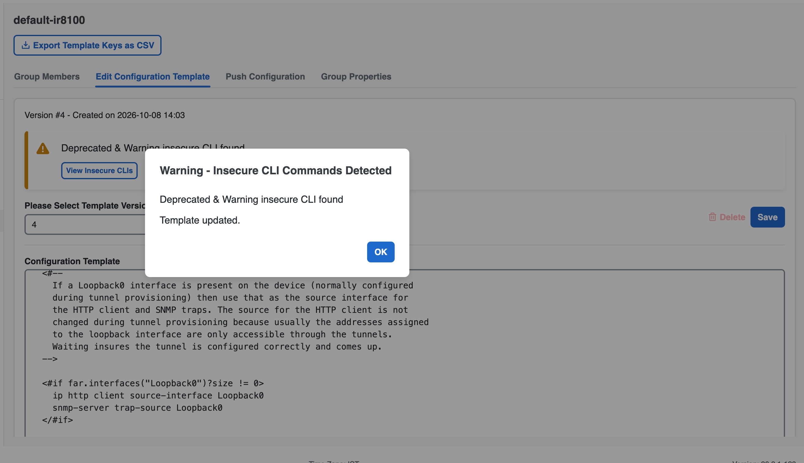
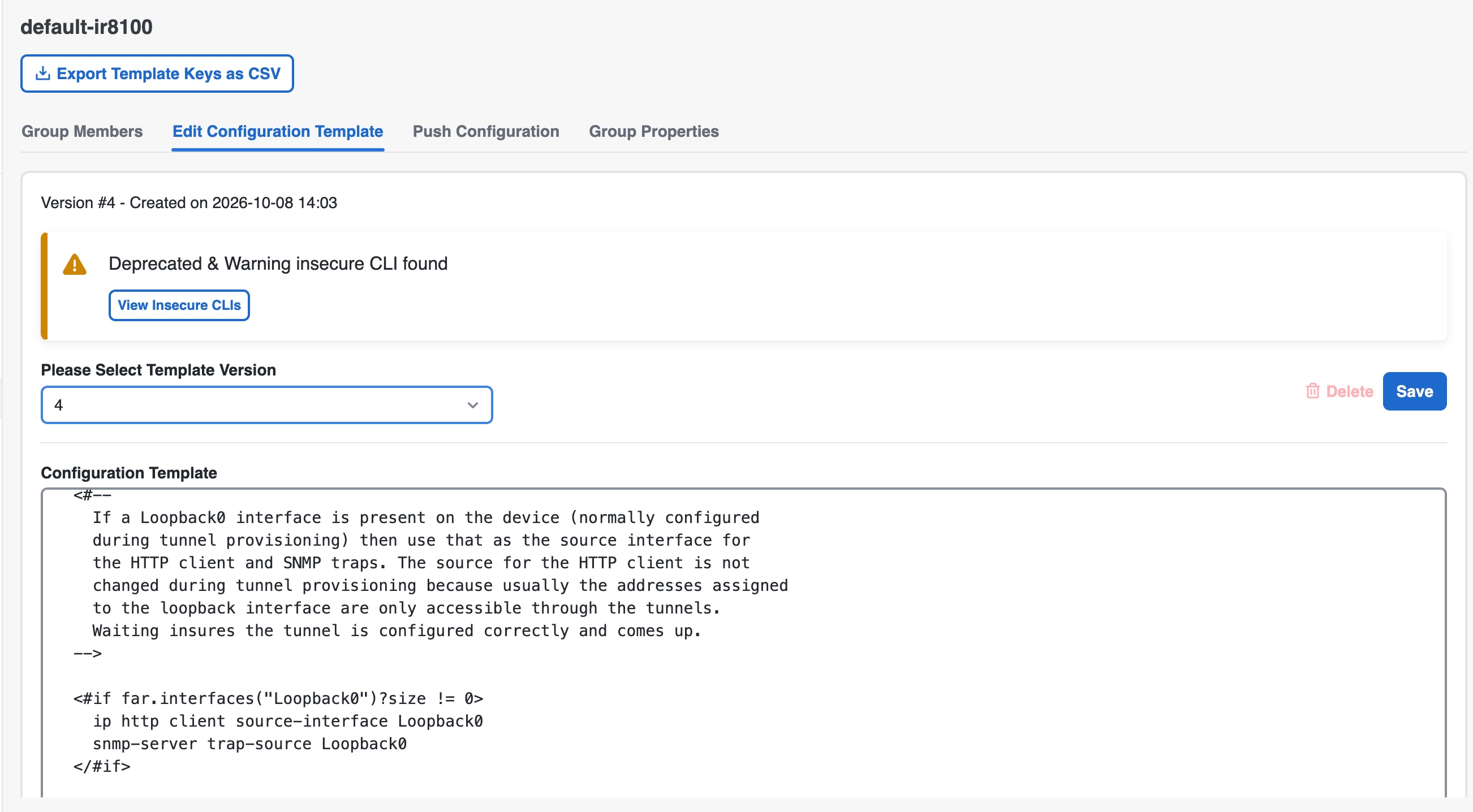
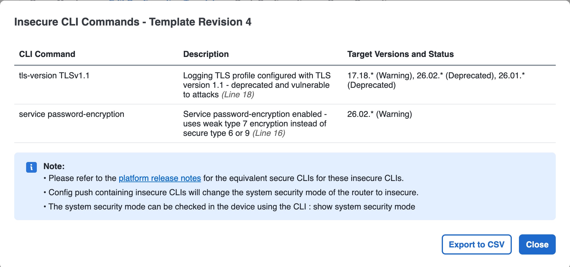
 Feedback