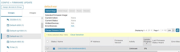
Router Firmware Updates
IoT FND updates router firmware in two steps:
Procedure
|
Step 1 |
Uploads the firmware image from IoT FND to the router. Firmware images upload to the flash:/managed/images directory on the router.
|
||||||
|
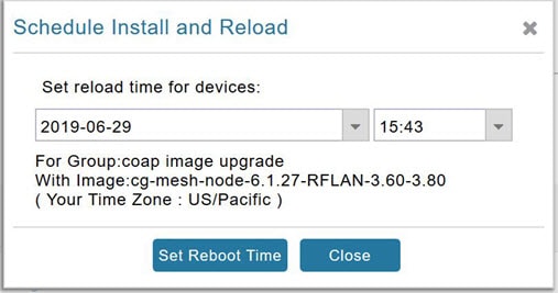
Step 2 |
Installs the firmware on the device and reloads it. During the firmware install the boot parameters on the routers are updated according to the new image file and the router is reloaded after enabling the cg-nms-register cgna profile.
When a router contacts IoT FND for the first time to register and request tunnel provisioning, IoT FND rolls the router back to the default factory configuration (ps-start-config) before uploading and installing the new firmware image.
|
Upgrading Guest OS Images
Depending on CGR factory configuration, a Guest OS (GOS) may be present in the VM instance. You can install or upgrade Cisco IOS on the page (see Router Firmware Updates). The GOS, hypervisor, and Cisco IOS all upgrade when you perform a Cisco IOS image bundle installation or update.
After any Cisco IOS install or upgrade, when IoT FND discovers a GOS, it checks if the initial communications setup is complete before it performs the required setup. The CGR must have a DHCP pool and GigabitEthernet 0/1 interface configured to provide an IP address and act as the gateway for the GOS. The new GOS image overwrites existing configurations. IoT FND has an internal backup and restore mechanism that ports existing apps to the upgraded Guest OS. See Monitoring a Guest OS for more information.
See Cisco 1000 Series Connected Grid Routers Configuration Guides for information on configuring the CGR.
Note: If IoT FND detects a non-Cisco OS installed on the VM, the firmware bundle will not upload and the Cisco reference GOS will not install.
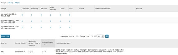
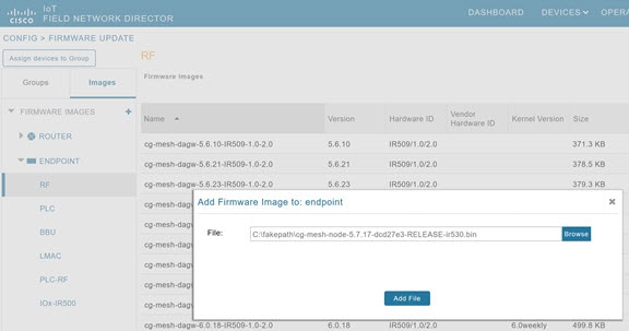
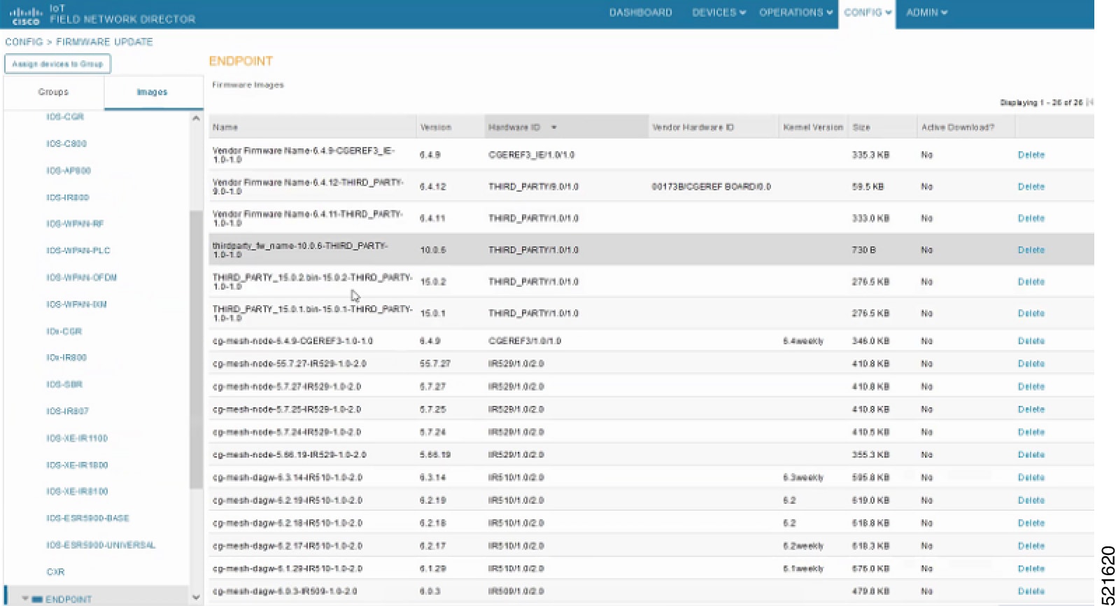
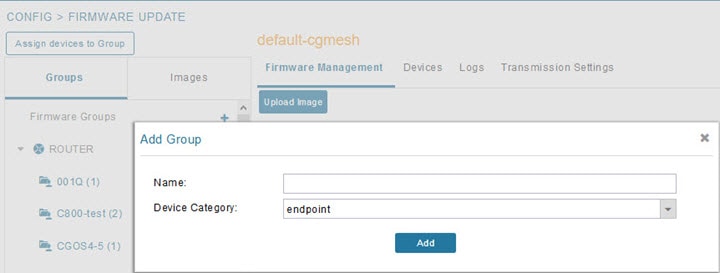
Upgrading WPAN Images
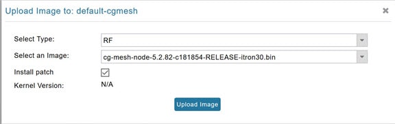
At the page, you can upload the independent WPAN images (IOS-WPAN-RF, IOS-WPAN-PLC, IOS-WPAN-OFDM, IOS-WPAN-IXM) to IoT FND using the Images sub-tab (left-hand side) and Upload Image button like other image upgrades. This process is known as a non-integrated WPAN firmware upgrade.
Note: The WPAN firmware image integrated with the IOS CGR image option is still supported.
Also, if only the WPAN firmware upgrade from the image bundled with IOS image is desired (for example, when the WPAN firmware upgrade option was not checked during IOS upgrade), the “Install from Router” option is also provided under respective WPAN image types (IOS-WPAN-RF or IOS-WPAN-PLC).
For detailed steps, go to Firmware images.
Changing Action Expiration Timer
You can use the cgnms_preferences.sh script to set or retrieve the action expiration timer value in the IoT FND database:
/opt/cgms
/bin/cgnms_preferences setCgrActionExpirationTimeout 50
Valid options are:
Procedure
|
Step 1 |
set <pkg>actionExpirationTimeoutMins<value> where:
|
|
Step 2 |
setCgrActionExpirationTimeout <value> |
|
Step 3 |
get <pkg>actionExpirationTimeoutMins |
|
Step 4 |
getCgrActionExpirationTimeout Example In the following example, the action timer value is retrieved, set, the current value retrieved again, the value removed, and a null value retrieved: |


 Feedback