Manage devices

Device management is the process of monitoring, configuring, and maintaining network-connected hardware within the Cisco IoT FND platform.

In the Devices menu, you can add, update, and remove devices, and perform other device management tasks that do not include device configuration. Under Devices, the sub-menu options such as Field Devices, Head-End Routers, Servers, and Asset include Browse Devices that provide a list of routers, endpoint, or gatewaus available for management.

The table includes all possible options available under Browse Devices.

Browse Devices options

Description

Routers

Includes router models such as CGR1000, IR800, IR1100 Pluggable and Expansion Modules (IR-1100-SP).

Enables you to view the devices based on the status such as Up, Down, and Unheard.

Head-End Routers

Includes ASR1000, ISR3900, ISR4000, C8000, and so on.

Enables you to view the devices based on the status such as Up, Down, and Unheard.

Endpoints

Includes meters and IR500 gateways

Enables you to view the devices based on the status such as Up, Down, and Unheard.

IoT Gateways

Includes LoRaWAN gateway (IXM-LPWA-900) and IC3000

Enables you to view the devices based on the status such as Up, Down, and Unheard.


Note


In some textual displays of the Cisco IoT FND, routers may display as “FAR” rather than the router model (cgr1000, etc).


Field Area Routers (FARs)

Field Area Routers are core components of a Field Area Network that provide connectivity between field devices, such as meters, sensors, and control equipment, and the head-end routers.

Cisco Iot FND enables you to,

  • manage the FAR lifecycle,

  • perform configuration and maintenance activities, and

  • monitor and troubleshoot router performance.

Supported Field Area Routers

Cisco IoT FND supports the following Field Area Routers:

  • Cisco Catalyst IR1800 Rugged Series Routers

  • Cisco Catalyst IR8100 Heavy-Duty Series Routers (IR8140)

  • Cisco Catalyst IR1100 Rugged Series Routers (IR1101)

  • Cisco 1000 Series Connected Grid Routers (CGR1120 and CGR1240)

  • Cisco 800 Series Industrial Integrated Services Routers (IR800)

  • Cisco 800 Series Routers

Cisco also identifies Cisco 800 Series Access Points (AP800) as supported when integrated with C800 and IR829 devices.

Add router device files

Use the Device File Management page to manage router device files within the application.

Procedure


Step 1

Navigate to Config > Device file management .

Step 2

Select Actions > Upload to open the Upload File to Routers page.

Step 3

Search for the router device file using the full name or an abbreviated string.

  • Search by full name (for example, CGR1120/K9+JAF1648BBCK).

  • Search by an abbreviated device file string (for example, CGR120/K9+JAF or BBCK) to display a range of available routers.

Step 4

Select the routers for the upload.

The system displays the number of router files available based on your search criteria, with all routers selected by default. You can adjust the display count using the drop-down menu (options: 10, 50, 100, 200) and clear the check boxes for any routers you do not want to include.

Step 5

Click Upload .


Delete files from routers

Free up device storage by deleting files from routers using the device file management interface.
Use this task when you need to clear unnecessary or outdated files from routers within a device group. This helps maintain available storage and ensures devices remain operational.

Follow these steps to remove files from routers:

Procedure


Step 1

From the main menubar, choose Config > Device File Management.

Step 2

From the left pane, select the file that you want to delete.

Step 3

On the Actions tab, click Delete .

The Delete file from List dialog box appears.

Step 4

Select a file to delete.

You can delete the file from all routers in the selected group or any subset of routers in the group.

Step 5

Click Delete File .

The Delete File from Routers dialog box displays.

Step 6

Check the check boxes of the routers from which you want to delete the file.

  • You can click Change File to select a different file to delete from the selected routers.

  • You can select multiple routers.

  • Only one file can be deleted at a time.

  • You can click Clear Selection and (x) close the windows to stop deletion.

Step 7

Click Delete .

If there are no file transfer or deletion, configuration push, firmware upload, or install or reprovision operations in progress for the group, the delete operation begins. Cisco IoT FNDsearches the.../managed/files/ directory on the devices for the specified file name.

Note


On deletion, all file content is purged from the selected devices, but not from the Cisco IoT FND database. File clean-up status displays for the selected group.

You can select another group and file to perform a separate file deletion while file transfer or deletion processes are in progress for this group. When you cancel file deletion process before it completes, the currently running file deletion process completes and all waiting file deletion processes are cancelled.

File operations status, progress percentage, and any error messages are displayed in the job status area.

The selected file is deleted from the chosen routers. File deletion status is displayed for all affected devices; unsuccessful deletions will display error information for follow-up action.

Structure of router import records in Notice-of-Shipment XML files

This reference provides the structure of the <R> record used for importing router configurations into Cisco IoT FND.

You use the Notice-of-Shipment XML file sent to you by your Cisco partner. This file contains an <R> record for every router shipped to you. This is an example of an <R> record for a CGR:

<AMI>
	<Re1ays>
		<DCG deviceC1ass=?10.84.82.56?>
			<PID>CGR1240/K9</PID>
			<R>
				<ESN>2.16.840.1.114416.3.2286.333498</ESN>
				<SN>FIXT:SG-SALTA-10</SN>
				<wifiSsid>wifi ssid 1</wifiSsid>
				<wifiPsk>wifi psk 1</wifiPsk>
				<adminPassword>ppswd 1</adminPassword>
				<type6PasswordMasterKey>secret 1</type6PasswordMasterKey>
				<tunne1SrcInterface1>Ethernet2/3</tunnelSrcInterface1>
			</R>
		</DCG>
	</Re1ays>
</AMI>

Note


For a list of all Device Properties that you can configure using the XML configuration template, refer to Device Properties .


Table 1. Router Import Fields
Field Description

PID

The product ID, as supplied by Cisco. This is not printed on the product.

SN

The router serial number.

Note


Cisco IoT FND forms the router EID by combining the PID and SN.

ESN

A serial number assigned by your Cisco partner to the WPAN mesh card inside the router. This field is not used by Cisco IoT FND.

wifiSsid

This information is configured on the router by your Cisco partner during the manufacturing configuration process. Cisco IoT FND stores this information in its database for future use.

wifiPsk

adminPassword

adminUsername

type6PasswordMasterKey

tunnelSrcInterface1

View router details

Enable network administrators to access, monitor, and review router information through the Field Devices page.

You use the Field Devices page to view network devices for monitoring and configuration. By default, devices are shown in the Default view.

Procedure


Step 1

Navigate to Devices > Field Devices.

Step 2

Under Browse Devices pane, review the listed network devices available for monitoring or configuration.

The Field Devices page displays devices in the Default view by default.


You can see detailed information for each router, allowing you to monitor status and configure devices as needed.

View router device properties

The Field Devices page defaults to the List view, which contains basic device properties, unless you select the Default to map view option in user preferences.

Procedure

Step 1

Select a router or group of routers in the Browse Devices pane.

Step 2

Click the desired tab in the main pane to view specific device properties.

Each tab displays different sets of device properties. For example, the Default view displays basic device properties, while the Cellular-GSM view displays properties specific to the cellular network.


What to do next

For information on customizing router views, see Customize device views . For details on device properties, see Device Properties . For common actions such as adding labels, see Common device operations .

View routers in map view

Before you begin

Access the User Preferences page to enable the map feature.

Procedure

Step 1

Select the root or user name at the top, upper-right-hand corner of the screen and click Preferences .

Step 2

Select the Enable map checkbox.

Note

 
The additional options are found as selectable options on the User Preferences page (Servers, Show PAN ID in Hexadecimal).

Step 3

Navigate to Devices > Field Devices , choose the router, and click Map .


The RPL tree connection displays data traffic flow as blue or orange lines:

  • Orange lines indicate that the link is an uplink: data traffic flows in the up direction on the map.

  • Blue lines indicate that the link is a downlink: data traffic flows in the down direction on the map.


Note


You can view any RPL tree by clicking the device in Map view, and closing the information pop-up window.

View router usage statistics

From Cisco IoT FND release 4.11 onwards, the Device Details page provides a new Router Usage Stats chart for the Cisco IOS (CGR1000 and IR800) and IOS-XE (IR1101, IR8100, IR1800) devices. This chart displays the historical trend of the CPU, memory, and disk usage on an hourly (6 hours), daily (one day), weekly (one week), and monthly (four weeks) basis. You can also visualize the time-specific data by customizing the date and time. However, the maximum date range that you can define is limited to the data retention period specified in the UI ( refer to Configure data rention ). The data retention period that you can set ranges from a minimum of one to a maximum of 90 days.

For more information, see Set time filters to view charts .

Procedure

Step 1

Choose Devices > Field Devices > Browse Devices > ROUTER .

Step 2

Select the device type. The Inventory tab displays the devices for the selected device type. You can also filter the usage data based on CPU, memory, or disk.

Step 3

Click the required device on the right pane to view the Router Usage Stats chart for the selected device.


IOS-XE command execution in Cisco IoT FND UI

The IOS-XE command option in Cisco IoT FND is a Troubleshoot tab capability for running supported IOS-XE EXEC commands from the device details page during troubleshooting. This feature provides a controlled user-interface path for operational command execution, which can be used for Cisco IOS-XE device troubleshooting through the Cisco IoT FND user interface.

Role in device troubleshooting

The command option extends the device details workflow by letting users collect command output without leaving the Cisco IoT FND and logging into the device CLI.

Supported platforms

The IOS-XE command option is supported for these Cisco IOS-XE devices:

  • IR8140

  • IR1800

  • IR1100

  • IR1000

Command processing model

Cisco IoT FND validates command input before execution and sends accepted commands to the device. The UI returns the device output or an applicable error response after execution.

Table 2. Feature history

Release information

Feature name

Description

Cisco IoT FND Release 26.2.1

IOS-XE Exec command execution support in FND UI

Adds an IOS-XE command option to the device details Troubleshoot tab in Cisco IoT FND.

Use the Troubleshoot tab to execute IOS-XE commands

Use the Troubleshoot tab on a supported device details page to execute safe IOS-XE commands from the Cisco IoT FND user interface. The command output appears in the Response area.


Note


Use this tab only for supported operational commands that do not change device configuration or introduce security risks.


The Troubleshoot tab is available for supported Cisco IOS-XE devices, including IR8140, IR1800, IR1100, and IR1000.

Before you begin

  • Ensure that your user role has the Execute IOS-XE Commands permission.


    Note


    To grant the Execute IOS-XE Commands permission without modifying the base role, create a custom role that incorporates all existing permissions and the troubleshooting permission, and assign it exclusively to the users who need it. For instructions on creating and assigning a custom user role, refer Custom User Roles.


  • The selected device is a supported Cisco IOS-XE device and is not in the unmanaged, out of service, or unheard state.

  • No active firmware upload or upgrade is running for the selected device. You cannot execute commands while a firmware upload or upgrade is active.

Procedure

Step 1

Choose Devices > Field Devices, and in the Browse Devices pane, select the supported IOS-XE router device type.

The Field Devices page lists routers, endpoints, and gateways in the Browse Devices pane.

Step 2

Click the name of the device that you want to troubleshoot.

The device details page opens for the selected device.

Step 3

Click the Troubleshoot tab.

The tab is not visible for unsupported devices or for devices in the unmanaged, out of service, or unheard state. The feature supports device states such as registration and bootstrap.

Step 4

Click the information icon to review the supported command rules.

The information icon shows the supported commands, supported special characters, allowed characters, and disallowed characters. Cisco IoT FND validates commands in the UI and backend.

Step 5

In the Command field, enter a supported IOS-XE EXEC command or select a previously executed command from the drop-down list.

The command field uses show version as the placeholder example. Cisco IoT FND supports safe abbreviations, such as sh, tr, and tracert, when the abbreviations match the supported command rules.

Commands are limited to 200 characters. You can enter up to five supported commands with semicolons.

Note

 
  • Do not enter commands that change device configuration. If a command is unsupported, exceeds the command limits, or contains blocked characters or patterns, Cisco IoT FND displays an error popup and does not execute the command.

  • Cisco IoT FND retains up to 10 recently executed commands for each user and device combination. Duplicate commands are not retained as separate entries; the repeated command moves to the most recent position.

  • Cisco IoT FND stores the recent command list and the current command response in memory. The system clears these values after a service restart or upgrade.

    Cisco IoT FND also persists command execution history and responses in the database. The persisted records remain available for export through Export PDF.

Step 6

In the Timeout (sec) field, keep the default timeout value or enter a longer timeout value.

Step 7

Click Execute.

Command execution occurs in the background. You can navigate to other screens while the command runs.

The Response area shows command execution progress while the command is running.

Step 8

Review the command output in the Response area.

The Response area expands with vertical and horizontal scroll bars for long command output.

If a network-related error occurs, Cisco IoT FND displays the applicable error popup. Network-related errors include device unreachable, connection timeout, network cable unplugged, device rebooting, and WSMA service downtime.

You can use the Clear Responses button to clear the Response text field.

Step 9

(Optional) To export the command-history records of the device,

  1. In Export Count, enter the number of previously executed command history records to export. You can export from 1 to 500 records.

  2. Click Export PDF.

    When you click Export PDF, the exported filename uses the format export-command-history-<DeviceEID>-<Timestamp>.pdf.


Cisco IoT FND displays the IOS-XE command output or applicable error response and records the command execution in the audit log with the user identity, command, and execution timestamp.

Filter routers using built-in filters

You can refine the list of displayed routers by using the built-in router filters such as Up, Down, or Unheard status available under ROUTERS in the Browse Devices pane. You can also use the saved custom searches in the Quick View pane.

Procedure


Step 1

From the main menu, choose Devices > Field Devices

Step 2

In the Browse Devices pane, locate ROUTERS.

You can also apply the saved custom seaches from the Quick View tab.

Step 3

Under status, select the desired filter (for example, Up, Down, Unheard) to apply it.

The list updates to show routers matching the selected status in the right pane.

Selecting a filter inserts a corresponding search string (e.g., status:up) into the Search field automatically. For example, clicking the Up filter under ROUTERS inserts the search string status:up.

To filter routers by system security mode, use the System Security Mode filter or enter a search string such as systemSecurityMode:secure.

You can also use the saved custom searches from the Quick View pane to apply frequently-used filters.


View router configuration groups

Use the Browse Devices pane to display routers that belong to one of the groups (such as CGR1000) listed under ROUTER.

Procedure


Step 1

Navigate to the Devices > Field Devices page.

Step 2

From the Browse Devices pane, select the desired group listed under ROUTER to display the associated routers.


View router firmware groups

Allow administrators to review and confirm which firmware versions are available for various router models.
Use this task to check the firmware versions associated with router groups, ensuring the correct images are available before applying updates.

Follow these steps to verify available firmware images for router groups:

Procedure


Step 1

Choose Config > Firmware Update.

Step 2

From the left pane, click the Groups tab and choose the desired router group (for example, Default-cgr1000, Default-ir1100, Default-ir800 or ).

Step 3

Review the firmware images displayed under the Name field for each selected router group.

For groups like Default-ir800, multiple router models such as IR809 and IR829 may be listed with corresponding firmware images.

You can view and verify the available firmware images associated with each router group, ready for further update actions as needed.

View router tunnel groups devices

A router tunnel group is used to organize and manage router devices within the network infrastructure. Viewing these associations helps streamline device management and troubleshooting.

Follow these steps to view router devices assigned to tunnel groups:

Procedure


Step 1

From the main menu, choose Config > Tunnel Provisioning.

Step 2

Locate and select the desired router tunnel group under the ROUTER listing.

Step 3

Review the list of router devices associated with the selected tunnel group.


Export mesh routing tree data

Export mesh routing tree data for a selected router, including the parent-child node hierarchy, to an Excel (.xlsx) file.

Cisco IoT FND exports routing information for the parent node (router) and its associated child nodes (meters) from the Mesh Routing Tree tab. The Excel (.xlsx) file captures the multihop parent-child hierarchy in separate sheets for each hop level. By default, each sheet displays the parent nodes for that hop level. Expand or collapse the rows to view the parent-child relationships.

Before you begin

  • This export option is available only for routers, not for other device categories such as endpoints.

  • Ensure that your environment supports Microsoft Excel files and has sufficient storage for the exported file.

Follow these steps to export mesh routing tree data:

Procedure


Step 1

Choose Devices > Field Devices > Browse Devices > Routers.

Step 2

Click the device for which you want to export routing tree data.

The Device Info page appears.

Step 3

Click the Mesh Routing Tree tab.

Step 4

Click Export Routing Tree.

The Excel file is saved to the file system with the following name:

export-routingtree-<timestamp>.xlsx

The exported data captures the relationships between the root node and its associated child nodes. The first sheet is named Root. Subsequent sheets are named Hop-level-<hop number>, such as Hop-level-1 and Hop-level-2.

Starting with Cisco IoT FND Release 26.2.1, when location information is available, the exported file includes the latitude and longitude coordinates of each device.

  • The Root sheet provides information about the parent node (router) and its first-hop child nodes.

  • The subsequent Hop-level-<hop number> sheets provide information about the child nodes at each hop level.

For Cisco IR8100 routers, the exported routing tree data is based on the selected WPAN interface.


Router push configuration count

The router push configuration count is a system parameter that limits the volume of concurrent configuration updates sent to network devices.

  • Controls the rate of configuration delivery.

  • Prevents device overload during mass updates.

  • Ensures sequential processing of network changes.

Router Push Configuration Count management

Manage and track the number of configuration changes applied to a group of routers during the configuration push using Cisco IoT FND.

Table 3. Feature History

Feature Name

Release

Description

Manage Router Push Configuration Count

Cisco IoT FND Release 5.0

Define the number of router configuration changes or updates that you want to apply to routers within a specific group, simultaneously. Manage and track the number of configuration changes applied to a group of routers during the configuration push using Cisco IoT FND.

Router Push Configuration Count Per Group value

The Router Push Configuration Count Per Group is a configuration parameter that determines the maximum number of parallel router push operations allowed within a group.

  • The default value is 5.

  • The maximum permissible value is 100.

  • The configuration value applies globally to all router push configurations.


Note


Define the Router Push Configuration Count Per Group value globally to all router push configurations using Cisco IoT FND. The maximum parallel or concurrent router push configuration count is applied to all the group of routers.


Benefits of managing router push configuration count

This reference outlines the operational advantages of using the router push configuration count feature to optimize network management and minimize manual configuration risks.

The following benefits are associated with managing router push configuration counts:

  • Adaptability: You can quickly adapt configuration counts to meet changing network requirements, enhancing overall network management.

  • Error Reduction: The Router Push Configuration Count Per Group field minimizes the risk of errors that might occur with manual file edits.

Configure router push configuration count

Procedure

Step 1

From the main menu, choose Admin > Server Settings > Property Settings .

Step 2

Enter the number of router push configurations to be pushed to a group in the Router Push Configuration Count Per Group field.

The maximum number of router push configurations you can enter is 16.

Step 3

Click Save.

The router push configuration count is set.


Push configurations to routers

Use this task to push configuration to routers.

Router configuration pushes are performed from the Push Configuration tab for selected router groups or subsets.


Note


CGRs, IR800s, and ISR 800s can coexist on a network; however, you must create custom configuration templates that include the router types.


Procedure


Step 1

Choose Config > Device Configuration.

Step 2

Select the group or subset of a group to push the configuration to the Configuration Groups pane.

Step 3

Click the Push Configuration tab to display that window.

Step 4

In the Select Operation drop-down list, choose Push ROUTER Configuration.

For IR800 groups with embedded AP devices, choose Push AP Configuration to push the AP configuration template.

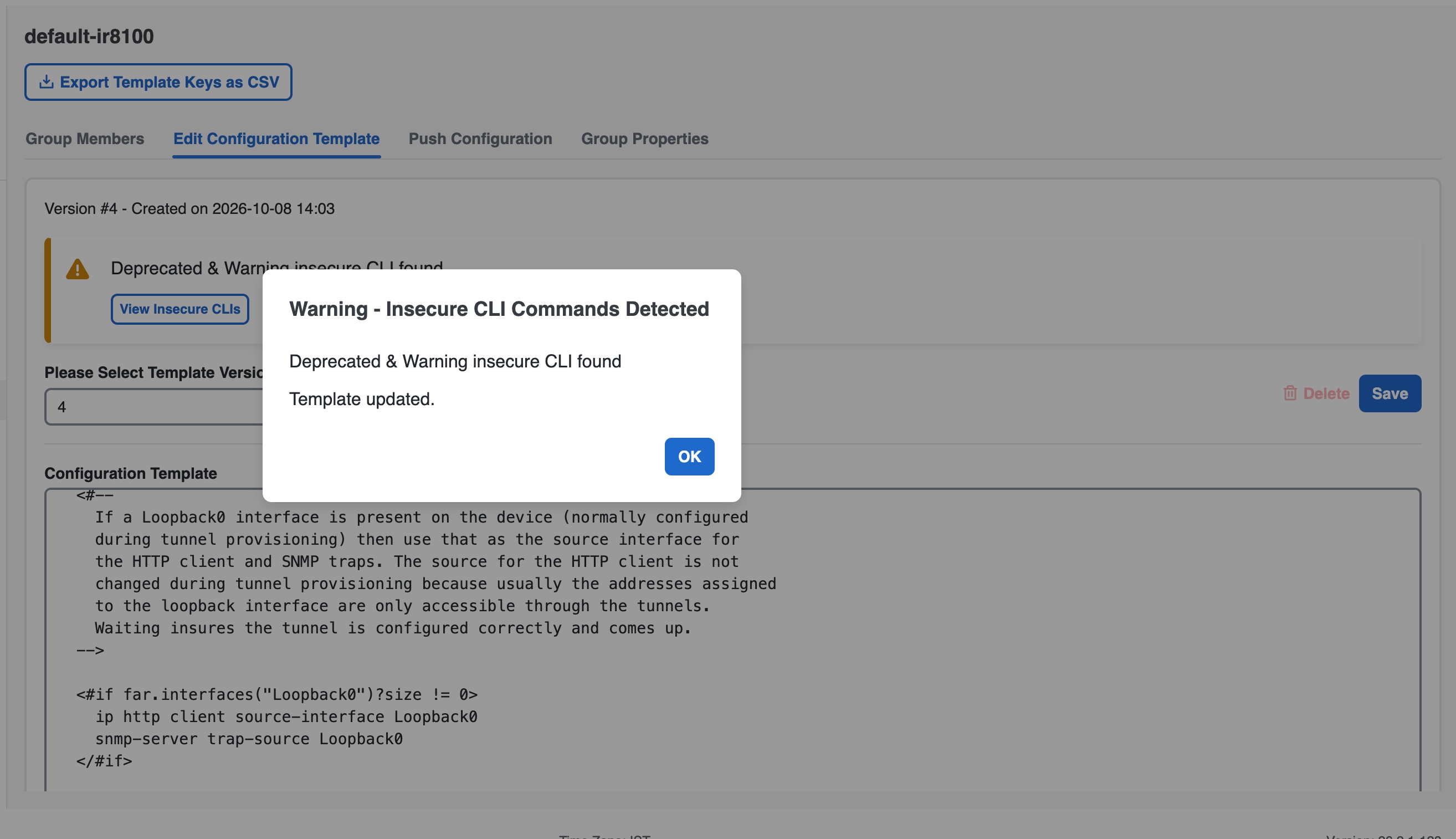
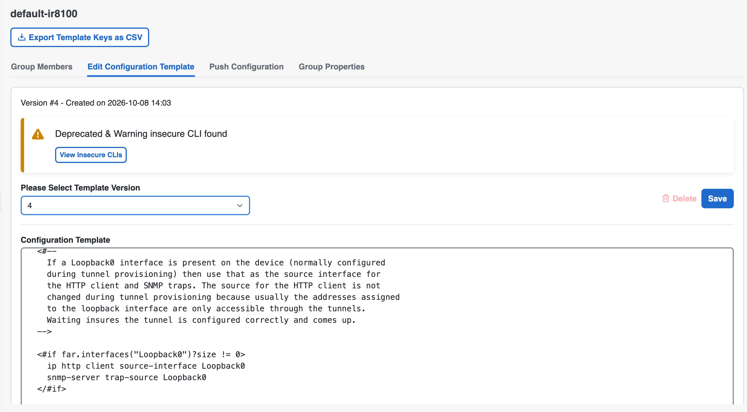
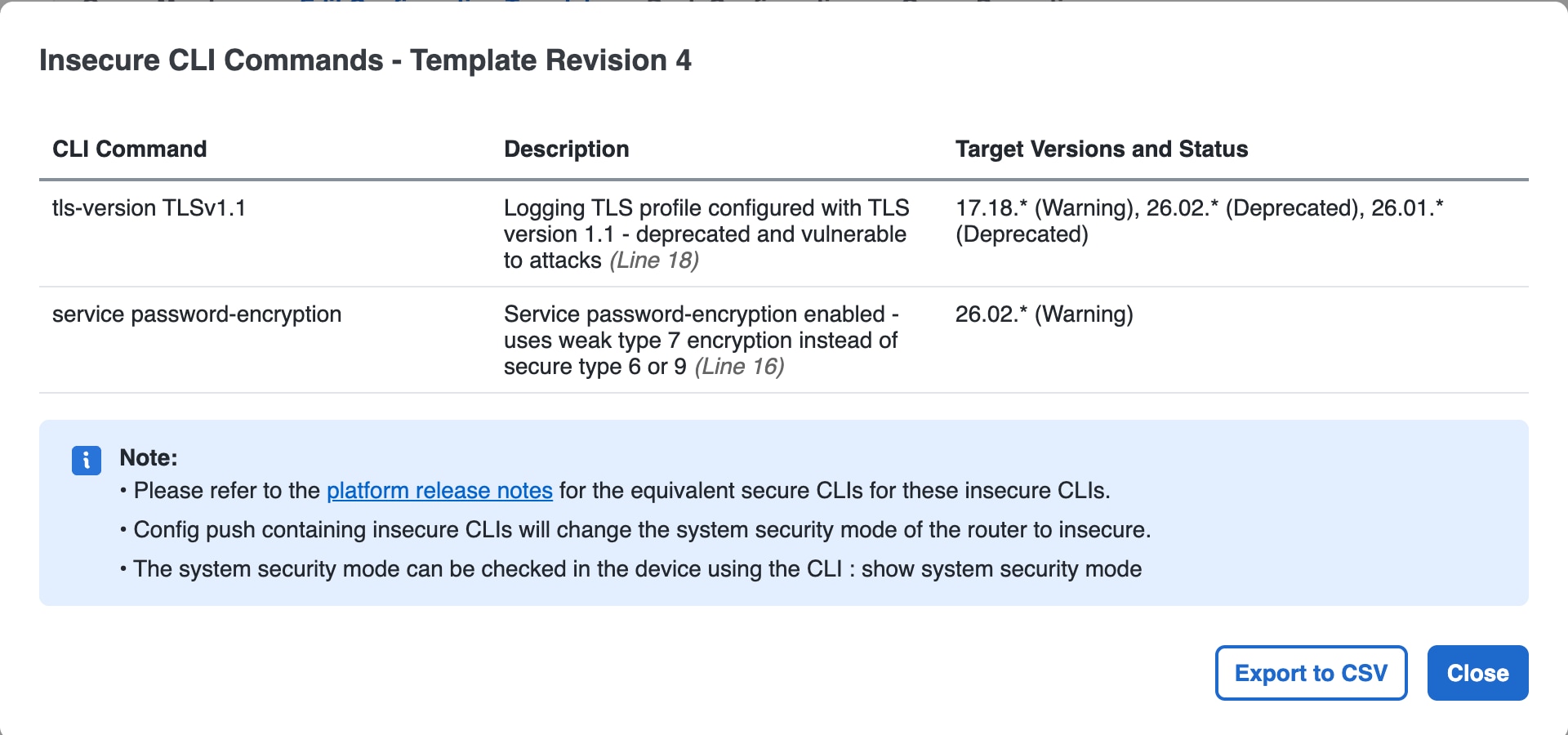
If the router configuration contains a deprecated insecure CLI command and the target router is in secure mode, Cisco IoT FND moves the router to insecure mode before applying the configuration.

Step 5

In the Select Operation drop-down list, choose Push ENDPOINT Configuration .

Step 6

Click Start.

The Push Configuration page displays the status of the push operation for every device in the group. If an error occurs while pushing configuration to a device, the error and its details display in the relevant columns.

If a push operation includes deprecated insecure CLI commands, review the warning or error message details in the device status table after the operation completes.

In the Status column, one of these values appears:

  • NOT_STARTED — The configuration push has not started.

  • RUNNING — The configuration push is in progress.

  • PAUSED — The configuration push is paused. Active configuration operations complete, but those in the queue are not initiated.

  • STOPPED — The configuration push was stopped. Active configuration operations complete, but those in the queue are not initiated.

  • FINISHED — The configuration push to all devices is complete.

  • STOPPING — The configuration push is in the process of being stopped. Active configuration operations complete, but those in the queue are not initiated.

  • PAUSING — The configuration push is in the process of being paused. Active configuration operations complete, but those in the queue are not initiated.


What to do next


Note


To refresh the status information, click the Refresh button.


Note


After deprecated insecure CLI commands are removed from the template and router configuration, use the Move to Secure Mode operation on the Push Configuration tab to move the router back to secure mode.


Enable SD card password protection

Use this task to enable CGR SD card password protection.

Password protection for the SD card in the CGR helps prevent unauthorized access and prevents transference of the CGR SD card to another system with a different password.

The Device Info pane displays CGR SD card password protection status in the Inventory section. The Config Properties tab displays the SD card password in the Router Credentials section.

Before you begin


Note


This does not apply to IR800s.


Procedure

Step 1

Choose Config > Device Configuration.

Step 2

Select the CGR group or CGRs to push the configuration to in the Configuration Groups pane

Step 3

Select the Push Configuration tab.

Step 4

In the Select Operation drop-down menu, choose Push SD Card Password

Step 5

Click Start. Click Yes to confirm action or No to stop action.

Step 6

Select SD Card protection > Enable.

Step 7

Select the desired protection method:

  • Property: This password is set using a CSV or XML file, or using the Notification Of Shipment file.

  • Randomly Generated Password: Enter the password length.

  • Static Password: Enter a password.

Step 8

Click Push SD Card Password.


Replace routers in Cisco IoT FND

Before you begin

Before proceeding with a Return Material Authorization (RMA) for any device integrated with Cisco IoT FND that you want to replace, perform these steps:

Procedure


Step 1

Perform a backup of the configuration from the router that you want to replace.

Step 2

Install the new router in the same location as the router that you want to replace.

Step 3

Before connecting the new device to the network, restore the configuration from the backup device.

Step 4

Verify if the new router that you are adding as a replacement is functioning as expected while it is connected to the network.


What to do next


Note


For more details on how to add new FAR devices and routers, see Managing Devices .


Improved Audit Trail

The Improved Audit Trail is a security feature that enables the systematic tracking and extraction of user and system events.

  • Supports CSV format for external analysis.

  • Maintains detailed event timestamps and user identifiers.

  • Facilitates automated log retention and archival.

CSV file download for audit trail

Provides access to .CSV files used for adding, removing, or editing devices within Cisco IoT FND to maintain an accurate audit trail.

Table 4. Feature History

Feature Name

Release

Description

Improved Audit Trail

Cisco IoT FND Release 5.0

When you add, remove, or edit files using .CSV files on Cisco IoT FND, a log is generated in the Audit Trail page. You can download the .CSV file that you used to change the devices.

Information about improved Audit Trail

The enhanced Audit Trail page provides direct access to .csv files for device actions performed in Cisco IoT FND Release 5.0 and later.

  • Provides direct download links for .csv files.

  • Supports tracking of changes made through .csv file uploads.

  • Includes logs for actions performed via NBAPIs.


Note


Download the .CSV file logs even when you use NBAPIs for your device actions.


Benefits of improved audit trail

This reference outlines the advantages of the improved audit trail, specifically focusing on transparency, accountability, and simplified record management through .csv file downloads.

  • Gain immediate access to detailed records of device management actions, allowing for clear and transparent auditing of changes made via .csv files. This helps maintain accountability and ensures compliance with organizational policies.

  • Downloading and storing the .csv files directly from the audit trail simplifies record-keeping practices.

Download CSV files from audit trail

You can download audit trail CSV files from the Cisco IoT FND system management interface.

Procedure

Step 1

From the Cisco IoT FND menu bar, choose Admin > System Management > Audit Trail.

Step 2

Locate a log entry for Devices added , Changed Device Properties , or Devices removed in the audit trail list.

Step 3

In the Details column, find the clicable CSV link.

Step 4

Click the CSV file to download the file.

The CSV file contains information such as the timestamp, user ID, and device details.


Router admin password rotation in Cisco IoT FND

Cisco IoT FND supports router administrator password rotation for supported Cisco IOS and Cisco IOS XE devices. The feature uses the rotate_admin_password.sh script in the Cisco IoT FND cgms tools package and a CSV file that maps device identifiers to administrator passwords. This script is either run manually or scheduled using a cron job

The cgms tools package can be installed on a Cisco FND Oracle Bare Metal, a Postgres VM, or a separate VM. FND installation is not required on the separate VM. For information on installing cgms tools on a separate VM, see Install CGMS Tools RPM on a separate VM .

The following topics describe supported platforms, CSV file requirements, manual password rotation, and scheduled password rotation.

Table 5. Password rotation support

Feature

Release

Description

Admin Password Rotation

Cisco IoT FND Release 5.0

The Cisco IoT FND tools package includes the rotate_admin_password.sh script with CSV input to rotate administrator passwords across Cisco IoT FND devices that use Cisco IOS or Cisco IOS XE.

Supported platforms

This reference lists the supported Cisco IOS and Cisco IOS-XE device types for the current environment.

The supported device types are:

  • Cisco IOS Device Types: CGR1000 and IR800

  • Cisco IOS-XE Device Types: IR8100, IR1800, and IR1100

Prerequisites

Complete the following prerequisites before executing the rotate_admin_password script:

  • Password preference synchronization in the command.txt file and the device configuration.

  • Define parameters in the CSV File .

  • Ensure that routers are in Up state.

  • No active operation such as config push, firmware upgrade should be running in Cisco IoT FND.

Deployment Configuration

Based on the deployment type, copy the required files to the cgms-tools package.

  • Oracle Bare Metal Deployment

    Filename

    Copy From

    Copy To

    .fnd_psk_enc

    /opt/cgms/server/cgms/conf/.fnd_psk_enc

    /opt/cgms-tools/conf

    fnd_psk.keystore

    /opt/cgms/server/cgms/conf/fnd_psk.keystore

    /opt/cgms-tools/conf

    jdbc.properties

    /opt/cgms/tools/conf/jdbc.properties

    /opt/cgms-tools/conf/jdbc.properties

    cgms_keystore

    /opt/cgms/server/cgms/conf/cgms_keystore

    /opt/cgms-tools/conf

    cgms.properties

    /opt/cgms/server/cgms/conf/cgms.properties

    /opt/cgms-tools/conf

  • Postgres Virtual Machine Deployment

    Copy From

    Copy To

    docker cp fnd-container:/opt/cgms/server/cgms/conf/.fnd_psk_enc /opt/cgms-tools/conf

    /opt/cgms-tools/conf

    docker cp fnd-container:/opt/cgms/server/cgms/conf/fnd_psk.keystore

    /opt/cgms-tools/conf

    docker cp fnd-container:/opt/cgms/tools/conf/jdbc.properties

    /opt/cgms-tools/conf/jdbc.properties

    docker cp fnd-container:/opt/cgms/server/cgms/conf/cgms_keystore

    /opt/cgms-tools/conf

    docker cp fnd-container:/opt/cgms/server/cgms/conf/cgms.properties

    /opt/cgms-tools/conf

Password preference synchronization

Password preference synchronization is the process of matching the device-level password type with the corresponding command defined in the command.txt file.

  • Device configuration must match the command.txt entry.

  • Plaintext configurations require the password command.

  • Encrypted configurations require the secret command.

  • Router password configuration: The router is configured with either plaintext or secret password.

  • Command.txt file: The command.txt file has two commands, namely "password" and "secret" as shown below. Based on the password configured in the device (plaintext or secret), provide the command (password or secret) in the command.txt file.

    username {username} privilege 15 password {password}
    username {username} privilege 15 secret {password}
Password combinations for synchronization

The table lists the allowed password combinations for a successful admin password rotation.

Table 6. Supported Password Combinations

Device Configuration

Command.txt

Plaintext

Password (plaintext)

Encrypted

Secret


Attention


The admin password rotation fails if there is a password preference mismatch in the command.txt and the router configuration. The following table lists the password preference combinations that are not supported.

Table 7. Unsupported Password Combinations

Device Configuration

Command.txt

Plaintext

Secret

Secret

Plaintext


CSV File

The CSV file is a configuration input that maps device identifiers to their respective admin passwords for the rotation process.

The rotate_admin_password script is executed based on the information you provide in the CSV file, which contains the device EID and the password.

The CSV file requires the following information for device password rotation:

  • EID: The EID can either be router-specific or HER-specific. If you provide the HER EID, the admin password is rotated for all the routers that are associated with the HER. If you provide the router-specific EID, the admin password is rotated for that specific router.

  • Password : Cisco IoT FND provides options for plaintext, encrypted, or blank password fields in the CSV file.

CSV File Configuration Details

The CSV file serves as a configuration input that maps device identifiers to their respective admin passwords for the rotation process.

The following table outlines the password options available for the CSV file:

Plaintext Password

In the CSV file, provide a password that is a combination of uppercase (A-Z), lowercase (a-z), numbers (0-9), and special character ( !@#$%^&*.).

Sample CSV file for routers :

EID,ADMINPASSWORD
IR1101-K9+FCW2226006G,cisco123!
IR1101-K9+FCW2226004G,Cisco123
IR8140H-P-K9+FDO2J46Z,pdsL$123
Encrypted Password

If you want to encrypt the admin password, use the signature tool.

Sample CSV file for routers :

In the following example, the plaintext password is encrypted using the signature tool.

[root@iot-tps bin]# cat Single_Device_encrypted.csv
EID,ADMINPASSWORD
IR1831-K9+FCW2729Y2QV,VAXKhqI03xomp40f9xdyhIqYl4hh+6pztOAsRGwhrFUjD0xp+
F7zrIJUWOHpBiGC7yVIsqZyb70AEPuLVuZXGFLU/gQ9wpDSkoBNLVyxBYkSABD5vBG5Z2OS
TtaSva3xjnR9kGnw2P30nXSxEB2PNYHjpi8NVQLEiAz8JwVWLePt2xs6v+kXmsKYFrxZE6e2
Q5Mi9z+FW5COSiDLpt1//aLHIQIzR3QHgsiCi0RG/dVxvBn4Ra6NdYBqAsl17GVcFyvkSJhNs
KyeW0bPvuDpAAgRiga2i3rlJ5m0im/eT513aQWJXjHOotJmU/6sZ4jDzWQKop96modyEYuzrvNQrg==
Blank

If the admin password field is blank in the CSV file, the password is autogenerated.

Sample CSV file for routers :

EID,ADMINPASSWORD
IR1101-K9+FCW2226005G                    

Sample CSV file for HERs :

HEREID,ADMINPASSWORD
CSR1000V+9J04F38WNBP

Note


  • Regardless of your password preference (plaintext, encrypted, or blank) specified in the CSV file:

    • The admin password is encrypted in the Cisco IoT FND logs, which is decrypted using the signature tool.

    • The admin password appears either in plaintext or secret format depending on the password preference set in the command.txt file and the device configuration. For more information, see Password preference synchronization .

  • To see the password in the Cisco IoT FND, navigate to Devices > Field Devices > Config Properties Tab > Router Credentials .


Customize parallel administrator password updates

By default, you can update passwords on up to 20 routers in parallel. You can customize the default value of 20 based on your deployment needs.

Procedure

Step 1

Locate the configuration file at /opt/cgms-tools/conf/rotate-admin-password.properties.

Step 2

Edit the rotate-admin-password.properties file using a text editor.

Step 3

Locate the rotate_admin_pwd_thread_count=20 attribute.

Step 4

Change the value to the desired number of threads.

Example:
rotate_admin_pwd_thread_count=50

Configure the generated password length for router admin rotation

Use the rotate-admin-password properties file to set the length of passwords that Cisco IoT FND generates. The default generated password length is 15 characters.

Cisco IoT FND creates a password automatically when the ADMINPASSWORD field in the CSV file is blank for router-specific rotation or during HER-level password rotation. You can configure the auto-generated password length during password rotation.

Follow these steps to configure the generated password length for router admin rotation.

Procedure

Step 1

Open the configuration file located at /opt/cgms-tools/conf/rotate-admin-password.properties using a text editor.

Step 2

Locate the generated_admin_pwd_length attribute.

The default password length is 15.

Step 3

Change the value of generated_admin_pwd_length to your desired password length.

Example:
generated_admin_pwd_length=30

The maximum password length is 100 characters.

Step 4

Save the rotate-admin-password.properties file.

Step 5

Run the rotate_admin_password.sh script, providing the required CSV file as input.

In the CSV file, keep the ADMINPASSWORD field blank to have Cisco IoT FND generate the router administrator password during password rotation.


Cisco IoT FND uses the length you specified for automatically generated router administrator passwords during password rotation.

Update administrator passwords on multiple routers

The rotate_admin_password.sh script is available with the cgms tools package in the Cisco IoT FND bundle OVA/rpm at /opt/cgms-tools/bin/rotate_admin_password.sh. It supports Cisco IOS and Cisco IOS XE device types.

Procedure

Step 1

Specify the password rotation details in the CSV file.

For router-specific rotation, specify the router EID and the password in the CSV file. The password can be plaintext, secret, or system generated.

For HER level rotation, specify the HER in the CSV file. The password is system-generated and rotated for all devices that tunnel with the specified HER.

Step 2

Run the rotate_admin_password.sh script with the CSV file.

Example:
$ ./rotate_admin_password.sh <csv-file>

Note


The <csv-file> is the path to the CSV file containing the list of EIDs and admin passwords.


Success case:

[root@iot-fnd log]# cat rotate_admin_password_status_1750360977943.csv
                "EID","MESSAGE","STATUS"
                "IR1831-K9+FCW2729Y2QL",
                "Successfully updated the admin password.
                The new password is <rotated password>","SUCCESS"

Failure case:

[root@iot-fnd-oracle log]# cat rotate_admin_password_status_1749039357401.csv
                "EID","MESSAGE","STATUS"
                "IR1101-K9+FCW2708YA7X","'adminPassword' length must be greater than or equal to 3,
                'adminPassword' must contain at least 3 out of 4 types: uppercase, lowercase, numbers,
                permitted special characters !""#$%&'()*+,-./:;<=>@[]^_`{|}~","FAILURE"

Rotate the router admin password manually

Use this task to rotate the router admin password manually.

Manual password rotation uses the router admin password rotation script and a CSV file that lists EIDs and admin passwords.

Before you begin

Completing the Prerequisites is a must.

Procedure

Step 1

Run the script to change the password for the router admin.

$ ./rotate_admin_password.sh <csv-file>

The CSV file contains the list of EIDs and admin passwords. For more information, see CSV File.

Step 2

On successful execution of the script, disconnect and reconnect to the router with the new password.

  1. If the password update is successful, the database is updated with the new password and the Tcl script updates the password in the before-tunnel-config, before-registration-config, and express-setup-config.

  2. If the password update fails, refer to the log for more information.

    You can see the log for more information on the success or failure status, which is available at: /opt/cgms-tools/log/rotate-router-admin-password.log.

  3. For consolidated success and failure logs on specific devices, you can view them in .csv file.

    For example, rotate_admin_password_status_123.csv


What to do next

Upon successful script execution, verify if the operations such as refresh metrics, config push, firmware upgrade are working fine in FND.

Schedule admin password rotation with CronJob

This topic provides guidance on scheduling the rotate_admin_password script as a cron job during monthly maintenance windows. We recommend scheduling the cron job during the monthly maintenance window to avoid conflicts with the active operations in Cisco IoT FND. For example, schedule the script to run at 12:00 AM on the first day of every month.

The script automation is supported for these deployments:


Note


For a successful password rotation, it is recommended to allow a 24-hour gap between each script execution.


Schedule Oracle bare metal deployment

Use this task to schedule admin password rotation for Oracle bare metal deployment.

Oracle bare metal deployments use a crontab entry to run the router admin password rotation script on a schedule.

Before you begin

Complete the Prerequisites before scheduling admin password rotation.

Procedure

Oracle Bare Metal Deployment: Run the script to schedule for the password rotation.

$ cd /etc
$ crontab -e   
#Add below line in crontab. Save the file
0 0 1 * * /opt/cgms-tools/bin/rotate_admin_password.sh <location to csv>

Note


Ensure the CSV file is properly formatted and accessible. For more information, see CSV File.


What to do next

Upon successful script execution, verify if the operations such as refresh metrics, config push, firmware upgrade are working fine in Cisco IoT FND.

Schedule Postgres VM deployment

Use this task to schedule admin password rotation for Postgres VM deployment.

Postgres VM deployments require the CGMS Tools RPM, database access in pg_hba.conf, and cron scheduling for password rotation.

Before you begin

Complete the Prerequisites before scheduling admin password rotation.

Procedure

Step 1

Install or upgrade the tools rpm in VM.

  1. For install use the command rpm -ivh as given in the example:

    rpm -ivh  cgms-tools-5.0.0-117.x86_64.rpm
  2. For upgrade use the command rpm -Uvh as given in the example:

    rpm -Uvh cgms-tools-5.0.0-117.x86_64.rpm

Step 2

Enable the db connection in pg_hba.conf with the following entry.

host    all             all             <VM IP with Subnet>           scram-sha-256
Example:
Replace <VM IP with Subnet> with 203.0.113.10/32

Step 3

Restart postgresql.

service postgresql-12 stop
service postgresql-12 start

Step 4

Copy the following files from the docker container to the cgms-tools package.

  • docker cp fnd-container:/opt/cgms/server/cgms/conf/.fnd_psk_enc /opt/cgms-tools/conf

  • docker cp fnd-container:/opt/cgms/server/cgms/conf/fnd_psk.keystore /opt/cgms-tools/conf

  • docker cp fnd-container:/opt/cgms/tools/conf/jdbc.properties /opt/cgms-tools/conf/jdbc.properties

  • docker cp fnd-container:/opt/cgms/server/cgms/conf/cgms_keystore /opt/cgms-tools/conf

  • docker cp fnd-container:/opt/cgms/server/cgms/conf/cgms.properties /opt/cgms-tools/conf

Step 5

Provide Postgres IP in the jdbc.properties as below.

jdbc.url=jdbc:postgresql://<Postgres IP>:5432/cgms

Step 6

Add the route in the server for the device reachability. Also, make sure the devices are reachable from the VM.


What to do next

After the script executes successfully, verify if the operations such as refresh metrics, config push, firmware upgrade are working fine in Cisco IoT FND.

Cisco IoT FND WPAN

Cisco Wireless Personal Area Network (WPAN) is a short-range wireless network that connects devices within a small area, typically implemented through Cisco Connected Grid WPAN modules for routers.

  • Supports multiple network-based applications.

  • Operates using Cisco routers.

  • Provides robust security features for access control, device identity, key management, and encryption.

WPAN Feature History

Table 8. Feature History

Feature Name

Release Information

Description

Support of Dual WPAN for IR8100

Cisco IoT FND Release 4.8.1

Cisco IoT FND 4.8.1 supports dual WPAN on IR8100 routers. The dual WPAN support allows you to add more endpoints to the router. You can insert the WPAN modules in any of the three available UIM slots in IR8100 router.

WPAN Reboot in Cisco IoT FND

Cisco IoT FND Release 5.1

The Reboot WPAN button is added to the Device info page in Cisco IoT FND for these routers running:

  • Cisco IOS XE: Cisco Catalyst IR8140,

  • Cisco IOS: Cisco Connected Grid Router CGR1000.

View WPAN configuration

Use this task to view the WPAN configuration details.

Before you begin

You can use the example in this task to retrieve the current Dual-PHY WPAN device RPL slot tree, RPL slot table, RPL IP route info table, along with the configuration information for slots 4/1 and 3/1.

Procedure

Run the command as given in the example.

Example:
cisco-FAR5#show run int wpan 4/1
Building configuration... 
Current configuration : 320 bytes
!
interface Wpan4/1
 no ip address
 ip broadcast-address 0.0.0.0
 no ip route-cache
 ieee154 beacon-async min-interval 100 max-interval 600 suppression-coefficient 1
 ieee154 panid 5552
 ieee154 ssid ios_far5_plc
 ipv6 address 2001:RTE:RTE:64::4/64
 ipv6 enable
 ipv6 dhcp relay destination  2001:420:7BF:5F::500
end
cisco-FAR5#show run int wpan 3/1
Building configuration...
Current configuration : 333 bytes
!
interface Wpan3/1
 no ip address
 ip broadcast-address 0.0.0.0
 no ip route-cache
 ieee154 beacon-async min-interval 120 max-interval 600 suppression-coefficient 1
 ieee154 panid 5551
 ieee154 ssid ios_far5_rf
 slave-mode 4
 ipv6 address 2001:RTE:RTE:65::5/64
 ipv6 enable
 ipv6 dhcp relay destination  2001:420:7BF:5F::500
end
cisco-FAR5#show wpan 4/1 rpl stree
----------------------------- WPAN RPL SLOT TREE [4] -----------------------------
  [2001:RTE:RTE:64::4]
           \--(RF )-- 2001:RTE:RTE:64:207:8108:3C:1800    // SY RF nodes
           \--(RF )-- 2001:RTE:RTE:64:207:8108:3C:1801
                   \--(RF )-- 2001:RTE:RTE:64:207:8108:3C:1A00
           \--(RF )-- 2001:RTE:RTE:64:207:8108:3C:1802
           \--(RF )-- 2001:RTE:RTE:64:207:8108:3C:1803
           \--(RF )-- 2001:RTE:RTE:64:207:8108:3C:1804
\--(RF )-- 2001:RTE:RTE:64:207:8108:3C:1805
                   \--(RF )-- 2001:RTE:RTE:64:207:8108:3C:1A03
                   \--(RF )-- 2001:RTE:RTE:64:207:8108:3C:1A07
           \--(RF )-- 2001:RTE:RTE:64:207:8108:3C:1806
           \--(RF )-- 2001:RTE:RTE:64:207:8108:3C:1807
           \--(RF )-- 2001:RTE:RTE:64:207:8108:3C:1808
           \--(RF )-- 2001:RTE:RTE:64:207:8108:3C:1809
           \--(RF )-- 2001:RTE:RTE:64:207:8108:3C:180A
           \--(RF )-- 2001:RTE:RTE:64:207:8108:3C:180B
                   \--(RF )-- 2001:RTE:RTE:64:207:8108:3C:1A01
                           \--(RF )-- 2001:RTE:RTE:64:207:8108:3C:1C05
                           \--(RF )-- 2001:RTE:RTE:64:207:8108:3C:1C06
                           \--(RF )-- 2001:RTE:RTE:64:207:8108:3C:1C07
                   \--(RF )-- 2001:RTE:RTE:64:207:8108:3C:1A02
                   \--(RF )-- 2001:RTE:RTE:64:207:8108:3C:1A04
                   \--(RF )-- 2001:RTE:RTE:64:207:8108:3C:1A05
                           \--(RF )-- 2001:RTE:RTE:64:207:8108:3C:1C03
                           \--(RF )-- 2001:RTE:RTE:64:207:8108:3C:1C08
                           \--(RF )-- 2001:RTE:RTE:64:207:8108:3C:1C09
                           \--(RF )-- 2001:RTE:RTE:64:207:8108:3C:1C0A
                   \--(RF )-- 2001:RTE:RTE:64:207:8108:3C:1A06
                           \--(RF )-- 2001:RTE:RTE:64:207:8108:3C:1C02
                           \--(RF )-- 2001:RTE:RTE:64:207:8108:3C:1C04
                   \--(RF )-- 2001:RTE:RTE:64:207:8108:3C:1A08
                   \--(RF )-- 2001:RTE:RTE:64:207:8108:3C:1A09
                   \--(RF )-- 2001:RTE:RTE:64:207:8108:3C:1A0A
                           \--(RF )-- 2001:RTE:RTE:64:207:8108:3C:1C00
                           \--(RF )-- 2001:RTE:RTE:64:207:8108:3C:1C01
                           \--(RF )-- 2001:RTE:RTE:64:207:8108:3C:1C0B
                   \--(RF )-- 2001:RTE:RTE:64:207:8108:3C:1A0B
           \--(PLC)-- 2001:RTE:RTE:64:217:3BCD:26:4E00    // CY PLC nodes
           \--(PLC)-- 2001:RTE:RTE:64:217:3BCD:26:4E01
           \--(PLC)-- 2001:RTE:RTE:64:217:3BCD:26:4E02
           \--(PLC)-- 2001:RTE:RTE:64:217:3BCD:26:4E03
           \--(PLC)-- 2001:RTE:RTE:64:217:3BCD:26:4E04
           \--(PLC)-- 2001:RTE:RTE:64:217:3BCD:26:4E05
           \--(PLC)-- 2001:RTE:RTE:64:217:3BCD:26:4E06
           \--(PLC)-- 2001:RTE:RTE:64:217:3BCD:26:4E07
RPL SLOT TREE: Num.DataEntries 44, Num.GraphNodes 45 (external 0) (RF 36) (PLC 8)
cisco-FAR5#ping
 2001:RTE:RTE:64:217:3BCD:26:4E01
Type escape sequence to abort.
Sending 5, 100-byte ICMP Echos to 2001:RTE:RTE:64:217:3BCD:26:4E01, timeout is 2 seconds:
!!!!!
Success rate is 100 percent (5/5), round-trip min/avg/max = 254/266/294 ms
cisco-FAR5#ping
 2001:RTE:RTE:64:207:8108:3C:1C00
Type escape sequence to abort.
Sending 5, 100-byte ICMP Echos to 2001:RTE:RTE:64:207:8108:3C:1C00, timeout is 2 seconds:
!!!!!
Success rate is 100 percent (5/5), round-trip min/avg/max = 272/441/636 ms
cisco-FAR5#
cisco-FAR5#show wpan 4/1 rpl stable
------------------------------ WPAN RPL ROUTE SLOT TABLE [4] ------------------------------
NODE_IPADDR                   NEXTHOP_IP                    SSLOT LAST_HEARD
2001:RTE:RTE:64:207:8108:3C:1800        2001:RTE:RTE:64::4                      3      17:49:12    // SY RF nodes
2001:RTE:RTE:64:207:8108:3C:1801        2001:RTE:RTE:64::4                      3      18:14:05
2001:RTE:RTE:64:207:8108:3C:1802        2001:RTE:RTE:64::4                      3      18:14:37
2001:RTE:RTE:64:207:8108:3C:1803        2001:RTE:RTE:64::4                      3      17:56:56
2001:RTE:RTE:64:207:8108:3C:1804        2001:RTE:RTE:64::4                      3      17:48:53
2001:RTE:RTE:64:207:8108:3C:1805        2001:RTE:RTE:64::4                      3      17:47:52
2001:RTE:RTE:64:207:8108:3C:1806        2001:RTE:RTE:64::4                      3      17:49:54
2001:RTE:RTE:64:207:8108:3C:1807        2001:RTE:RTE:64::4                      3      17:46:38
2001:RTE:RTE:64:207:8108:3C:1808        2001:RTE:RTE:64::4                      3      18:22:01
2001:RTE:RTE:64:207:8108:3C:1809        2001:RTE:RTE:64::4                      3      17:50:02
2001:RTE:RTE:64:207:8108:3C:180A        2001:RTE:RTE:64::4                      3      17:50:02
2001:RTE:RTE:64:207:8108:3C:180B        2001:RTE:RTE:64::4                      3      18:24:00
2001:RTE:RTE:64:207:8108:3C:1A00        2001:RTE:RTE:64:207:8108:3C:1801        3      17:56:34
2001:RTE:RTE:64:207:8108:3C:1A01        2001:RTE:RTE:64:207:8108:3C:180B        3      18:27:34
2001:RTE:RTE:64:207:8108:3C:1A02        2001:RTE:RTE:64:207:8108:3C:180B        3      18:03:06
2001:RTE:RTE:64:207:8108:3C:1A03        2001:RTE:RTE:64:207:8108:3C:1805        3      18:25:18
2001:RTE:RTE:64:207:8108:3C:1A04        2001:RTE:RTE:64:207:8108:3C:180B        3      17:57:15
2001:RTE:RTE:64:207:8108:3C:1A05        2001:RTE:RTE:64:207:8108:3C:180B        3      18:23:39
2001:RTE:RTE:64:207:8108:3C:1A06        2001:RTE:RTE:64:207:8108:3C:180B        3      18:04:16
2001:RTE:RTE:64:207:8108:3C:1A07        2001:RTE:RTE:64:207:8108:3C:1805        3      17:55:00
2001:RTE:RTE:64:207:8108:3C:1A08        2001:RTE:RTE:64:207:8108:3C:180B        3      18:19:35
2001:RTE:RTE:64:207:8108:3C:1A09        2001:RTE:RTE:64:207:8108:3C:180B        3      18:02:02
2001:RTE:RTE:64:207:8108:3C:1A0A        2001:RTE:RTE:64:207:8108:3C:180B        3      18:18:00
2001:RTE:RTE:64:207:8108:3C:1A0B        2001:RTE:RTE:64:207:8108:3C:180B        3      18:02:46
2001:RTE:RTE:64:207:8108:3C:1C00        2001:RTE:RTE:64:207:8108:3C:1A0A        3      18:22:03
2001:RTE:RTE:64:207:8108:3C:1C01        2001:RTE:RTE:64:207:8108:3C:1A0A        3      18:24:03
2001:RTE:RTE:64:207:8108:3C:1C02        2001:RTE:RTE:64:207:8108:3C:1A06        3      18:25:03
2001:RTE:RTE:64:207:8108:3C:1C03        2001:RTE:RTE:64:207:8108:3C:1A05        3      18:15:05
2001:RTE:RTE:64:207:8108:3C:1C04        2001:RTE:RTE:64:207:8108:3C:1A06        3      18:24:05
2001:RTE:RTE:64:207:8108:3C:1C05        2001:RTE:RTE:64:207:8108:3C:1A01        3      18:10:02
2001:RTE:RTE:64:207:8108:3C:1C06        2001:RTE:RTE:64:207:8108:3C:1A01        3      18:05:03
2001:RTE:RTE:64:207:8108:3C:1C07        2001:RTE:RTE:64:207:8108:3C:1A01        3      18:11:03
2001:RTE:RTE:64:207:8108:3C:1C08        2001:RTE:RTE:64:207:8108:3C:1A05        3      18:15:05
2001:RTE:RTE:64:207:8108:3C:1C09        2001:RTE:RTE:64:207:8108:3C:1A05        3      18:15:04
2001:RTE:RTE:64:207:8108:3C:1C0A        2001:RTE:RTE:64:207:8108:3C:1A05        3      18:15:04
2001:RTE:RTE:64:207:8108:3C:1C0B        2001:RTE:RTE:64:207:8108:3C:1A0A        3      18:24:03
2001:RTE:RTE:64:217:3BCD:26:4E00        2001:RTE:RTE:64::4                      4      18:21:40
// CY PLC nodes
2001:RTE:RTE:64:217:3BCD:26:4E01        2001:RTE:RTE:64::4                      4      17:47:23
2001:RTE:RTE:64:217:3BCD:26:4E02        2001:RTE:RTE:64::4                      4      18:20:16
2001:RTE:RTE:64:217:3BCD:26:4E03        2001:RTE:RTE:64::4                      4      17:49:07
2001:RTE:RTE:64:217:3BCD:26:4E04        2001:RTE:RTE:64::4                      4      18:21:49
2001:RTE:RTE:64:217:3BCD:26:4E05        2001:RTE:RTE:64::4                      4      18:22:06
2001:RTE:RTE:64:217:3BCD:26:4E06        2001:RTE:RTE:64::4                      4      18:22:51
2001:RTE:RTE:64:217:3BCD:26:4E07        2001:RTE:RTE:64::4                      4      18:24:04
Number of Entries in WPAN RPL ROUTE SLOT TABLE: 44 (external 0)
cisco-FAR5#show wpan 4/1 rpl itable
----------------------------- WPAN RPL IPROUTE INFO TABLE [4] -----------------------------
NODE_IPADDR                   RANK  VERSION     NEXTHOP_IP                    ETX_P      ETX_LRSSIR  RSSIF HOPS  PARENTS     SSLOT
2001:RTE:RTE:64:207:8108:3C:1800        835   1     2001:RTE:RTE:64::4                      0     762   -67   -71   1     1     3    // SY RF nodes
2001:RTE:RTE:64:207:8108:3C:1801        692   2     2001:RTE:RTE:64::4                      0     547   -68   -67   1     1     3
2001:RTE:RTE:64:207:8108:3C:1802        776   2     2001:RTE:RTE:64::4                      0     711   -82   -83   1     1     3
2001:RTE:RTE:64:207:8108:3C:1803        968   2     2001:RTE:RTE:64::4                      0     968   -72   -63   1     1     3
2001:RTE:RTE:64:207:8108:3C:1804        699   1     2001:RTE:RTE:64::4                      0     643   -71   -66   1     1     3
2001:RTE:RTE:64:207:8108:3C:1805        681   1     2001:RTE:RTE:64::4                      0     627   -70   -64   1     1     3
2001:RTE:RTE:64:207:8108:3C:1806        744   1     2001:RTE:RTE:64::4                      0     683   -69   -68   1     1     3
2001:RTE:RTE:64:207:8108:3C:1807        705   1     2001:RTE:RTE:64::4                      0     648   -76   -63   1     1     3
2001:RTE:RTE:64:207:8108:3C:1808        811   2     2001:RTE:RTE:64::4                      0     811   -68   -69   1     2     3
2001:RTE:RTE:64:207:8108:3C:1809        730   1     2001:RTE:RTE:64::4                      0     692   -68   -70   1     1     3
2001:RTE:RTE:64:207:8108:3C:180A        926   1     2001:RTE:RTE:64::4                      0     926   -66   -68   1     1     3
2001:RTE:RTE:64:207:8108:3C:180B        602   2     2001:RTE:RTE:64::4                      0     314   -74   -69   1     1     3
2001:RTE:RTE:64:207:8108:3C:1A00        948   1     2001:RTE:RTE:64:207:8108:3C:1801        692   256   -73   -75   2     1     3
2001:RTE:RTE:64:207:8108:3C:1A01        646   2     2001:RTE:RTE:64:207:8108:3C:180B        323   256   -73   -75   2     3     3
2001:RTE:RTE:64:207:8108:3C:1A02        948   1     2001:RTE:RTE:64:207:8108:3C:180B        602   256   -73   -75   2     2     3
2001:RTE:RTE:64:207:8108:3C:1A03        803   2     2001:RTE:RTE:64:207:8108:3C:1805        503   256   -68   -78   2     3     3
2001:RTE:RTE:64:207:8108:3C:1A04        858   1     2001:RTE:RTE:64:207:8108:3C:180B        602   256   -65   -69   2     1     3
2001:RTE:RTE:64:207:8108:3C:1A05        646   2     2001:RTE:RTE:64:207:8108:3C:180B        323   256   -71   -69   2     2     3
2001:RTE:RTE:64:207:8108:3C:1A06        858   1     2001:RTE:RTE:64:207:8108:3C:180B        602   256   -73   -75   2     2     3
2001:RTE:RTE:64:207:8108:3C:1A07        979   1     2001:RTE:RTE:64:207:8108:3C:1805        627   352   -71   -73   2     1     3
2001:RTE:RTE:64:207:8108:3C:1A08        646   2     2001:RTE:RTE:64:207:8108:3C:180B        390   256   -75   -70   2     3     3
2001:RTE:RTE:64:207:8108:3C:1A09        948   1     2001:RTE:RTE:64:207:8108:3C:180B        602   256   -70   -69   2     3     3
2001:RTE:RTE:64:207:8108:3C:1A0A        646   2     2001:RTE:RTE:64:207:8108:3C:180B        390   256   -75   -71   2     2     3
2001:RTE:RTE:64:207:8108:3C:1A0B        858   1     2001:RTE:RTE:64:207:8108:3C:180B        602   256   -68   -68   2     2     3
2001:RTE:RTE:64:207:8108:3C:1C00        902   2     2001:RTE:RTE:64:207:8108:3C:1A0A        646   256   -70   -74   3     1     3
2001:RTE:RTE:64:207:8108:3C:1C01        902   2     2001:RTE:RTE:64:207:8108:3C:1A0A        646   256   -71   -72   3     1     3
2001:RTE:RTE:64:207:8108:3C:1C02        1114  1     2001:RTE:RTE:64:207:8108:3C:1A06        858   256   -74   -73   3     1     3
2001:RTE:RTE:64:207:8108:3C:1C03        1114  1     2001:RTE:RTE:64:207:8108:3C:1A05        858   256   -76   -77   3     1     3
2001:RTE:RTE:64:207:8108:3C:1C04        902   2     2001:RTE:RTE:64:207:8108:3C:1A06        646   256   -75   -68   3     2     3
2001:RTE:RTE:64:207:8108:3C:1C05        1114  1     2001:RTE:RTE:64:207:8108:3C:1A01        858   256   -66   -74   3     1     3
2001:RTE:RTE:64:207:8108:3C:1C06        1114  1     2001:RTE:RTE:64:207:8108:3C:1A01        858   256   -74   -72   3     1     3
2001:RTE:RTE:64:207:8108:3C:1C07        1114  1     2001:RTE:RTE:64:207:8108:3C:1A01        858   256   -70   -75   3     1     3
2001:RTE:RTE:64:207:8108:3C:1C08        1114  1     2001:RTE:RTE:64:207:8108:3C:1A05        858   256   -74   -70   3     1     3
2001:RTE:RTE:64:207:8108:3C:1C09        1114  1     2001:RTE:RTE:64:207:8108:3C:1A05        858   256   -70   -74   3     1     3
2001:RTE:RTE:64:207:8108:3C:1C0A        1114  1     2001:RTE:RTE:64:207:8108:3C:1A05        858   256   -70   -69   3     1     3
2001:RTE:RTE:64:207:8108:3C:1C0B        902   2     2001:RTE:RTE:64:207:8108:3C:1A0A        646   256   -76   -74   3     1     3
2001:RTE:RTE:64:217:3BCD:26:4E00        616   2     2001:RTE:RTE:64::4                      0     616   118   118   1     1     4    // CY PLC nodes
2001:RTE:RTE:64:217:3BCD:26:4E01        702   1     2001:RTE:RTE:64::4                      0     646   118   118   1     1     4
2001:RTE:RTE:64:217:3BCD:26:4E02        557   2     2001:RTE:RTE:64::4                      0     557   118   118   1     1     4
2001:RTE:RTE:64:217:3BCD:26:4E03        626   1     2001:RTE:RTE:64::4                      0     579   118   118   1     1     4
2001:RTE:RTE:64:217:3BCD:26:4E04        609   2     2001:RTE:RTE:64::4                      0     609   118   118   1     1     4
2001:RTE:RTE:64:217:3BCD:26:4E05        602   2     2001:RTE:RTE:64::4                      0     602   118   118   1     1     4
2001:RTE:RTE:64:217:3BCD:26:4E06        594   2     2001:RTE:RTE:64::4                      0     594   118   118   1     1     4
2001:RTE:RTE:64:217:3BCD:26:4E07        584   2     2001:RTE:RTE:64::4                      0     584   118   118   1     1     4
Number of Entries in WPAN RPL IPROUTE INFO TABLE: 44

The WPAN configuration details are displayed.

Configure SNMP v3 informational events

Use this task for enabling SNMP v3 informational events.

For Cisco IOS routers you configure SNMP v3 informational events to replace the default SNMP v3 traps. For Cisco IOS routers, converting these SNMP v3 traps to SNMP v3 informational events sends an acknowledgment to the router for every event received from the router.

The router then verifies if the trap is received by Cisco IoT FND or not.

Procedure

Run the commands given in the example after uncommenting the lines in the default configuration file.

Example:
<#-- Enable the following configurations for the nms host to receive informs 
instead of traps -->
<#-- no snmp-server host ${nms.host} traps version 3 priv ${far.adminUsername} -->
<#-- snmp-server engineID remote ${nms.host} ${nms.localEngineID} -->
<#-- snmp-server user ${far.adminUsername} cgnms remote ${nms.host} v3 auth sha 
${far.adminPassword} priv aes 256 ${far.adminPassword} -->
<#-- snmp-server host ${nms.host} informs version 3 
priv ${far.adminUsername} -->

The SNMP v3 informational events are enabled.

What to do next

Once the SNMP v3 informational events are enabled you can push the new configuration file to all routers in the group.

Enable router GPS tracking

Use this task to enable GPS traps.

You can enable GPS traps to trigger an event if the router moves a distance threshold, after a time threshold, or both.

For example, you can configure stationary, pole-top CGR monitoring for a distance threshold, to detect movement from theft or pole incident; for mobile routers, set both thresholds to determine distance over time.

Before you begin


Note


  • The recommended distance threshold is 100 feet (30 m).

  • Because GPS traps only generate informational logs, it is recommended that you create a rule-based event with high severity (such as CRITICAL) to inform the administrator of router movement. An example of this type of rule definition is:configGroup:name eventName:deviceLocChanged. For more information, see Creating a Rule .


Procedure

Run the command in the given example after uncommenting these lines in the default configuration template.

Example:

<#-- 
Enable the following configurations to generate events that track if the router 
moves by a certain distance (unit configurable) or within a certain time (in minutes) 
-->
<#-- cgna geo-fence interval 10 -->
<#-- cgna geo-fence distance-threshold 100 -->
<#-- cgna geo-fence threshold-unit foot -->
<#-- cgna geo-fence active -->

Router GPS tracking gets enabled.

WPAN reboot option in Cisco IoT FND

Cisco Wireless Personal Area Network (WPAN) is a type of wireless network that connects devices within a small area, supporting multiple network-based applications on Cisco routers.

  • Supports Cisco Catalyst IR8140 running Cisco IOS XE software.

  • Supports Cisco 1000 Series Connected Grid Router CGR1000 running Cisco IOS software.

  • Requires a router that supports the WPAN interface module.

WPAN Reboot Configuration

To reboot WPAN, use the Reboot WPAN button available in the device details page in Cisco IoT FND.


Note


You can use the Reboot WPAN option only for routers which support the WPAN interface module.


Reboot WPAN

Use this task to reboot WPAN in Cisco IoT FND.

The Reboot WPAN action is available from the Device Details page for supported routers.

Before you begin


Note


The Reboot WPAN feature in Cisco IoT FND works only for routers which have a WPAN interface.


Procedure

Step 1

From the main menu, choose Deviecs > Field Devices > Browse Devices > ROUTER.

Step 2

Select router from the ROUTER group.

Note


You can only select Cisco Catalyst IR8140 or Cisco Connected Grid Router CGR1000 as routers for rebooting WPAN in Cisco IoT FND.

Step 3

Click the router from the list of routers.

Step 4

Click Reboot WPAN in the device details page.

  1. Select the WPAN slot if more than one WPAN cards are available on the router.

You will receive a confirmation message, asking whether you want to continue with the reboot or not.

Step 5

Click Yes.

Note


If you do not wish to continue with the WPAN reboot, then you can click No.


Once WPAN has rebooted successfully, the status is displayed as Completed successfully.


Note


There are two scenarios in which WPAN reboot can fail:

  • WPAN reboot fails due to missing module: In this case the Reboot WPAN button is not enabled in the page and you do not have to perform any action in this case.

  • WPAN reboot fails even when the module is present but is not rebooting: In this case you will receive an error message asking you to wait for 30 seconds and then try rebooting again.


View WPAN reboot audit log
After the WPAN reboot is complete for a router, you can check the status of the router in the audit log.
Procedure

Step 1

From the main menu, choose Admin > System Management.

Step 2

Click Audit Trail .

The status of the router after WPAN reboot is displayed in the table.


View WPAN reboot events

Use this task to check the status of the routers after rebooting WPAN.

After the the WPAN reboot is complete for the selected routers, you can check the status of these routers in the Events page.

Procedure

Step 1

From main menu bar, choose Devices > Field Devices > Browse Devices > ROUTER.

Step 2

Select and click Cisco Catalyst IR8140 or Cisco Connected Grid Router CGR1000 router from the router group.

The device inventory page is displayed.

Step 3

Click Events .

Note


You can also view the events listed in the Cisco IoT FND OPERATIONS > Events page.


The status of the router after WPAN reboot is displayed in the table.

Dual WPAN support for Cisco Catalyst IR8100 router

Dual WPAN support is a configuration capability that allows Cisco IoT FND to manage multiple WPAN modules on a single Cisco Catalyst IR8100 router.

  • Supports insertion of WPAN modules into any of the three available UIM slots.

  • Maps inventory details and metrics based on the specific slot number of the module.

  • Provides slot-specific naming conventions for WPAN-related information to distinguish between multiple modules.

Cisco IoT FND uses the slot number in which the module is inserted for mapping the inventory details of the respective WPAN interface. In Cisco IoT FND, WPAN related information for the WPAN inserted in slot number 1 is displayed by default. The WPAN related information for the WPAN inserted in slot 2 or slot 3 are suffixed with corresponding slot number.

Key considerations

Before using the Cisco Catalyst IR8100 dual WPAN, observe the following configuration and operational requirements:

  • Display all WPAN parameters according to slot number, while user-configurable parameters display according to interface number.

  • Note that user-configurable parameters are not mapped by slot number. The existing parameters represent the first WPAN, and names with a suffix of 2 represent the second WPAN (for example, meshPrefixConfig, meshPrefixConfig2).

  • Re-register the device after adding or removing a WPAN.

  • Ensure the Cisco Catalyst IR8100 router firmware version is 17.08.01 or greater to support dual WPAN features in Cisco IoT FND 4.8.1. Cisco IoT FND maps the properties or metrics of WPAN based on the slot number in which it is inserted. If the firmware version is lower, Cisco IoT FND processes properties and metrics as it does for a single WPAN rather than by slot number.

    You can consider these two scenarios to understand how dual WPAN works with slot numbers. If the WPAN is inserted in slot 2 of the Cisco Catalyst IR8100 router with firmware version less than 17.08.01, the related properties or metrics always point to a set of attributes without the slot number suffix.

    • With Cisco IoT FND 4.8.1, the firmware upgrade of Cisco Catalyst IR8100 router from version less than 17.08.01 to a version greater than or equal to 17.08.01 leads the existing WPAN module to map the respective properties or metrics based on slot number. So the historic properties or metrics of the same Cisco Catalyst IR8100 router are mapped to one set of mesh properties or metrics (without slot number suffix) and the latest data is mapped to slot specific properties or metrics set.

    • After the Cisco IoT FND 4.8.1 upgrade, the already registered Cisco Catalyst IR8100 device with firmware version greater than or equal to 17.08.01 use the properties or metrics of the WPAN based on slot number. However, the historic properties or metrics of the same Cisco Catalyst IR8100 router is mapped to existing set of mesh properties or metrics (without the slot number suffix).

  • Understand that if a WPAN is inserted in slot 2 of a router with firmware version less than 17.08.01, related properties or metrics point to attributes without the slot number suffix.

  • Acknowledge that the High Availability feature is not supported for dual WPAN, consistent with its lack of support for single WPAN on the Cisco Catalyst IR8100 router.

Prerequisites for dual WPAN

Configure dual WPAN interfaces using different PAN IDs and IPv6 prefixes, while maintaining either the same or different SSIDs.

  • Ensure both WPANs remain in an Active-Active state in either WiSUN or CRMESH mode.

  • The dual WPAN interfaces are configured with: different PAN IDs and IPv6 prefixes, and same SSID or different SSID.


    Note


    Mix of stack modes is not supported.


Dual WPAN support in Field Devices

Provides details on accessing WPAN information and the FAN view within the Cisco IoT FND Field Devices page under Devices. The FAN view is available in the devices list inCisco IoT FND.

Add user configurable parameters for WPAN interfaces

Use this task to add user configurable parameters for both the WPAN interfaces.

Procedure

Step 1

From the main menu, navigate to Devices > Field Devices device list page.

Step 2

Upload a csv file.

For more information on uploading csv, see Changing Device Properties in Bulk .

Step 3

From the left pane. click the Browse Devices tab and select IR8100.

Step 4

Click Mesh Config tab to view the uploaded values.

You can also view the uploaded values using the Config Properties tab on the same page which has the Mesh Link Config details displayed for both the WPANs along with the parameters which are suffixed according to the slot number.


The user configurable parameters for both the WPAN interfaces are added.

Dual WPAN support in Router Device

Provides visibility into the number of endpoints connected to specific WPAN interfaces within the router device view.

In the Cisco IoT FND router device view, the Mesh Count column indicates the number of endpoints connected in the WPAN 0/1/0 inserted in slot 1. By default, the Mesh Count column is displayed. The mesh count 2 and mesh count 3 columns indicate the number of endpoints that are connected to WPAN 0/2/0 and WPAN 0/3/0. The mesh count 2 and mesh count 3 columns can be added in the Field Device page by choosing them to be in the default view. For more information, see Add Device Views .

View dual WPAN details in Cisco IR8100 router

Use this task to view the dual WPAN information in Cisco IR8100 router.

Procedure

From the main menu, choose Devices > Field Devices > IR8100 router.

Note

 
  • The Inventory > IR8100 device view displays the parameters for the WPAN inserted in slot 1 by default. The Mesh tab and Mesh Config tab displays the existing properties related to WPAN inserted in slot 1.

  • WPAN parameters are included for the WPANs that are inserted in other slots. You can view these additional attributes by customizing your default view.


The WPAN details in Cisco IR8100 router are displayed.

Add or edit a new tab in default view

Use this task for adding or editing a new tab in the existing default view of the dual WPAN in Cisco IR8100 router.

Procedure

Step 1

From the main menu, choose Devices > Field Devices > IR8100 router.

Step 2

Click + in the devices page, or

Step 3

Click the drop-down list near the Mesh tab or Mesh Config tab to edit the current view and add WPAN specific fields.

This helps to view WPAN related details specific to WPAN 0/2/0 or WPAN 0/3/0. For more information, see Customizing Device Views .


The new WPAN related tab is added.

View additional dual WPAN fields using filters

Use this task to view the filters based on the slot number in which the WPAN is inserted.

Before you begin


Note


The newly added WPAN parameters are displayed in the Show Filters option view.


Procedure

Step 1

From the main menu, choose Devices > Field Devices > IR8100 router.

Step 2

Click Show Filters in the default view.

Step 3

Select the WPAN parameters from the drop-down list.

Step 4

Enter the search criteria.


The search results are displayed in the page accordingly. For more information on filters, see Using Router Filters .

Access Device Info tab

The Device Info tab allows you to monitor parameters retrieved from both WPANs. Each section displays columns for the WPAN interface name with corresponding parameter values.

Procedure

Step 1

Navigate to Devices > Field Devices

Step 2

Click on a device to navigate to the Device Info tab.

Step 3

Review the settings under Mesh Link Settings , Mesh Link Metrics , and Mesh Link Keys sections.

Step 4

Review the Network Interface fields as described in the following table.

Table 9. Network interface fields

Field

Description

Interface

Indicates the name of the interface

Admin Status

Provides admin status (up/down)

Oper. Status

Provides operational status (up/down)

IP Address

Indicates the IP address of the device

Physical Address

Indicates the latitude and longitude of the device

Tx Speed (bps)

Indicates the speed (bits/sec) of data transmitted by the interface

Tx Drops (bps)

Indicates the number of packets dropped (drops/sec)

Rx Speed (bps)

Indicates the speed (bits/sec) of data received by the interface


What to do next

For more information on Mesh Link Settings , see Link Metrics .

For more information on Mesh Link Keys, see Mesh Link Keys .

View Device Info tab

Use this task to view the Cisco IoT FND Device Info tab.

Procedure

Step 1

From the main menu, choose Devices > Field Devices > IR8100 router.

Step 2

Click on router from the list of routers.

Note

 
  • The Network Interface table in the Device Info page provides the details of both the WPAN interfaces that are connected in any of the three available slots.

  • The Cisco IR8100 device is connected to CAM module through new virtual port group interface which is processed to retrieve information of the RPL tree. Based on the settings in the RPL tree, the mesh routing tree is displayed.

  • The Device Info tab displays the Mesh Link Traffic chart according to the time period selected on the top-right side of the page. The information given in the chart is color coded to distinguish the slot in which the WPAN is inserted. For example, the color used for Tx or Rx speed of WPAN in slot 1 is different from that of WPAN in slot 2.

  • You can click on the color code and the respective line in the chart is removed from the graph. This applies for all the charts.

  • The endpoint hop count chart shows an aggregated endpoint count between the hops connected to both the WPAN interfaces.


The Device Info page is displayed.

View dual WPAN events

Use this task to view the dual WPAN events in Cisco IoT FND.

Procedure

Step 1

From the main menu, choose Devices > Field Devices > IR8100 router.

Step 2

Click on router from the list of routers.

Step 3

Click Events tab.


The dual WPAN events page is displayed.

View Running Config tab

Use this task to view the Running Config tab in Cisco IoT FND.

Procedure

Step 1

From the main menu, choose Devices > Field Devices > IR8100 router.

Step 2

Click on router from the list of routers.

Step 3

Click Running Config tab.


The Running Config page gets displayed.

View Mesh Routing Tree

The Mesh Routing Tree tab allows you to select the available WPAN interface for which you want to see the mesh routing table information. For example, if you want to see the mesh routing tree information of WPAN inserted in slot number one, then you must select WPAN0/1/0.

Before you begin


Note


  • By default, the WPAN Interface drop-down list displays the WPAN interface inserted in lower slot number. Therefore, the information pertaining to the respective WPAN is displayed. So, you must select the available WPAN from the drop-down list for which you want to view the information.

  • During RPL tree polling, the information is fetched from both WPAN interfaces and processed by Cisco IoT FND. For more information on polling, refer to Configure RPL tree polling .

  • For the Cisco IR8100 device with CAM module, the RPL tree information is captured from the respective CAM module and displayed in the Mesh Routing Tree tab. The Cisco IR8100 device as the root element and the act devices connected to the CAM module are shown.


Procedure

Step 1

From the main menu, choose Devices > Field Devices > IR8100 router.

Step 2

Click on router from the list of routers.

Step 3

Click Mesh Routing Tree tab.

Step 4

Select the required WPAN slot number from the WPAN Interface drop-down list.

The table describes the fields under Mesh Routing Tree tab in the Device Info page.

Field Description

EID

Element Identifier.

Name

Router EID (Device identifier).

Status

Provides status of device (up/down).

Type

It represents the FAR and endpoint device type.

IP Address

Indicates the IP address of the device.

Last Heard

Last date and time the device contacted IoT FND.

Meter ID

Meter ID of the device.

Transmit Speed (bits/sec)

Indicates the speed (bits/sec) of data transmitted by the interface.

Packet Drops (packets/sec)

Indicates the number of packets dropped (drops/sec).

Receive Speed (bits/sec)

Indicates the speed (bits/sec) of data received by the interface.

RPL Hops (hops)

Number of hops that the element is from the root of its RPL routing tree.

RPL Link Cost (etx)

RPL cost value for the link between the element and its uplink neighbour.

RPL Path Cost (etx)

RPL path cost value between the element and the root of the routing tree.

RSSI

Shows the measured RSSI value of the primary mesh RF uplink (dBm) over time.

Reverse RSSI

RSSI received from the neighbour.

Active Link Type

Determines the most recent active RF or PLC link of a meter.


The table displays the mesh routing information for the selected WPAN.

Configure Dual WPAN support in Device Configuration

Dual WPAN is supported in the Cisco IoT FND Device Configuration page under the Config menu.

Procedure

Step 1

Navigate to the device configuration path.

Choose Config > Device Configuration > ROUTER > Default-Ir8100 .

Step 2

Configure WPAN parameters in the Group Members tab.

The table is updated with four more columns for representing the user configured parameters such as meshPrefixConfig2, meshPrefixLengthConfig2, meshPanIdConfig2, and meshAddressConfig 2 metrics. The existing parameter represents the first WPAN and the parameters with the suffix represent the configured parameter for the second WPAN.

Step 3

Define user configurable parameters in the Edit Configuration Template tab.

FND maps the defined parameters to the WPAN parameter value configured through CSV.

  1. Navigate to the Edit Configuration Template tab.

  2. Enter the parameter values in the template and click the disk icon. The WPAN specific user configurable parameters are displayed in the Running Config tab in the device details page.

Note


You can change device properties by clicking the Change Device Properties button above the devices pane.

Step 4

Export the template keys as a CSV file.

In the Device Configuration page, click the Export Template Keys as CSV button. The WPAN related user configurable parameters are exported in a CSV file.


View dual WPAN in Device Configuration page

Use this task to view the dual WPAN parameters in the Device Configuration page in Cisco IoT FND.

Procedure

From the main menu, choose Config > Device Configuration > ROUTER > Default-Ir8100 router.

Note


In the Group Members tab, the table is updated with four more columns for representing the user configured parameters such as meshPrefixConfig2, meshPrefixLengthConfig2, meshPanIdConfig2, meshAddressConfig 2 metrics. The existing parameter represents for first WPAN and the parameters with suffix represents the configured parameter for the second WPAN.


The dual WPAN details are displayed in the Device Configuration page.

Edit the dual WPAN user-configurable parameters

Use this task to edit the user configurable dual WPAN parameters in the Device Configuration page in Cisco IoT FND.

The Edit Configuration Template page allows you to define user configurable parameters in the template. Cisco IoT FND maps the defined parameters to the WPAN parameter value configured through CSV.

Follow these steps to edit the dual WPAN user-configurable parameters.

Procedure

Step 1

From the main menu, choose Config > Device Configuration > Router > Default-Ir8100 router.

Step 2

Click Edit Configuration Template .

Step 3

Enter the parameter values in Edit Configuration Template box.

Step 4

Click Save to apply the changes.

Note

 
  • You can change device properties by clicking the Change Device Properties button.

  • You can export the dual WPAN related user configurable parameters in a csv file format by clicking Export Template Keys as CSV button.


The user configurable dual WPAN parameters are edited and saved.

View dual WPAN in Dashboard

Use this task to view dual WPAN in the Dashboard page in Cisco IoT FND.

Procedure

Step 1

From the main menu, choose Dashboard .

Step 2

Click on the gear icon called Settings .

Step 3

Click Dashlets drop-down box in the Dashboard Settings window.

Step 4

Select the interface enabled devices from the Dashlets drop-down box.

Step 5

Click Close .

The Devices with interfaces enabled but down filter settings combo box is displayed.

Step 6

Select Type , Device , Interface , WPAN x|y|z .

Note


The Type refers to the type of device, Device refers to the router like Cisco IR8100 router, Interface is the WPAN x|y|z interface type listed in the drop-down box.

Step 7

Click Save .

A gauge chart with device interface is displayed.

Step 8

Click on the needle of the gauge chart.

The devices for which the interfaces are enabled is displayed in the gauge chart.


The status of the device interface is displayed in the form of a gauge chart.

PIMs in Cisco IoT FND

Pluggable Interface Modules (PIMs) are pluggable modular components that can be easily installed or removed on any router platform.

The PIMs are used for

  • configuring and upgrading network devices.

  • providing flexibility for adding different interfaces.

PIM Feature History

The following table lists the support history for various PIMs in Cisco IoT FND.

Table 10. Feature History

Release Information

Feature Name

Description

Cisco IoT FND Release 5.1

P-5GS6-GL PIM Support for Cisco Catalyst IR1800 and Cisco Catalyst IR1100 routers

Adds support for P-5GS6-GL 5G stand alone PIM for the Cisco Catalyst IR1800 and Cisco Catalyst IR1100 routers.

Cisco IoT FND Release 5.1

IRMH-5GS6-GL and IRMH-5GR16SA PIMs Support for Cisco Catalyst IR8100 routers

Adds support for IRMH-5GS6-GL and IRMH-5GR16SA stand alone PIMs for Cisco Catalyst IR8100 routers.

Cisco IoT FND 4.11

P-LTEA7-NA (EM7411), P-LTEA7-EAL (EM7421), and P-LTEA7-JP (EM7431) PIMs support for Catalyst IR1100 routers

Adds support for Cat7 LTE PIMs for North America, Rest of World, and Japan, supporting multiple slots and modems.

Cisco IoT FND Release 4.10

P-LTE-450 PIM support for Cisco Catalyst IR1100 routers

Adds support for P-LTE-450 Mhz or PIM, which is a third-party LTE module that supports private networks and operates at a 450 MHz frequency.

PIMs

This topic provides a comprehensive lookup table for PIM hardware support, detailing the specific router platforms, software requirements, and documentation links for each module.

Table 11. PIM Support Matrix

PIM Name

PID

Devices Supported

Minimum Supported Cisco IoT FND Release

Cisco IoT FND Supported Device Version

Description

P-LTE-450 MHz PIM

P-LTE-450

Cisco Catalyst IR1100

Cisco IoT FND Release 4.10

Cisco IOS XE Release 17.9.3 and later releases

Third-party LTE module (Cisco/Intelliport) for private LTE networks in the 450 MHz band; supports multi-PDN and multiple APNs per SIM; base or compute slot only. For more details, see Cisco Catalyst IR1100 Rugged Series Router

LTE Cat7 PIM (North America)

P-LTEA7-NA (EM7411)

Cisco Catalyst IR1101

Cisco IoT FND Release 4.11

Cisco IOS XE Release 17.13.1 and later releases

LTE Cat7 cellular pluggable module for North America; supports dual modem configuration; can be inserted in base, expansion module, or compute module slots. For more details, see Cisco Catalyst IR1101 Rugged Series Router Hardware Installation Guide

LTE Cat7 PIM (Rest of World)

P-LTEA7-EAL (EM7421)

Cisco Catalyst IR1101

Cisco IoT FND Release 4.11

Cisco IOS XE Release 17.13.1 and later releases

LTE Cat7 cellular pluggable module for regions outside North America and Japan; supports dual modem configuration; insertable in multiple slots. For more details, see Cisco Catalyst IR1101 Rugged Series Router Hardware Installation Guide

LTE Cat7 PIM (Japan)

P-LTEA7-JP (EM7431)

Cisco Catalyst IR1101

Cisco IoT FND Release 4.11

Cisco IOS XE Release 17.13.1 and later releases

LTE Cat7 cellular pluggable module for Japan region; supports dual modem configuration; can be inserted in base, expansion module, or compute module slots. For more details, see Cisco Catalyst IR1101 Rugged Series Router Hardware Installation Guide

5G Stand Alone PIM

P-5GS6-GL

Cisco Catalyst IR1800 and Cisco Catalyst IR1100

Cisco IoT FND Release 5.1

Cisco IOS XE Release 17.7.1 and later releases

5G stand-alone pluggable module for 5G and fallback 4G cellular connectivity; supports multiple APNs and interfaces; enhances flexibility on the IR1100 and IR1800 platforms. For more details, see Cisco Catalyst IR1800 Rugged Series Router Hardware Installation Guide , Cisco Catalyst IR1101 Rugged Series Router Hardware Installation Guide .

5G Stand Alone PIM

IRMH-5GS6-GL and IRMH-5GR16SA

Cisco Catalyst IR8100

Cisco IoT FND Release 5.1

Cisco IOS XE 17.17.1 and later releases

5G stand-alone pluggable module for 5G and fallback 4G cellular connectivity; robust wireless options; advanced networking for the IR8100 platform. For more details, see Cisco Catalyst IR8100 Heavy Duty Series Router

View PIMs in field devices page

Access detailed information about the PIM modules connected to a router for monitoring and troubleshooting.

Use this task to view these PIM details in the Device Info page: Use this task to view PIM details of a router’s interfaces, including their cellular link settings, Cellular Link Info, cellular Link Metrics, and Pluggable Module Info. This is useful for verifying configuration and diagnosing connectivity issues.

Before you begin


Note


  • The Network Interface table in the Device Info page displays the GigabitEthernet interfaces.

    • A P-LTE-450 MHz module connected to the base module uses interface GigabitEthernet 0/1/0.

    • The same module connected to the compute module uses interface GigabitEthernet 0/4/0.

  • P-LTE-450 can be connected in the base slot or expansion CM slot and always appears as Modem2. The APNs use 3, 4, and 5 as interface numbers.

  • Ensure that Cisco IoT FND has detected the router and the inserted module during device registration.


Follow these steps to view PIM details for a field device.

Procedure

Step 1

Choose Devices > Field Devices > Browse Devices > Router.

Step 2

Click the router you want to inspect from the list.

Step 3

On the Device Info page, view the following details:

  • Cellular Link Settings,

  • Cellular Link Info,

  • Cellular Link Metrics,

  • Pluggable Module Info.


The Device Info page displays PIM details for the selected router, including module, interface, and cellular metrics.


Note


What to do next

See View Metrics in the Cellular Link Traffic and RSSI Charts .

Display cellular module information after an upgrade

If a device was registered with Cisco IoT FND while running a Cisco IOS XE release earlier than 26.1.1, information about an installed cellular module might not appear on the Device Info page after you upgrade the device to Cisco IOS XE Release 26.x.

Selecting Refresh Metrics or waiting for periodic metrics collection does not update the inventory that Cisco IoT FND created during registration.

To display the cellular module information, remove the device from Cisco IoT FND and add it again.


Note


Removing a router from Cisco IoT FND returns its leased IP addresses to Cisco Network Registrar and removes its corresponding tunnels from the head-end routers. We recommend that you perform this procedure during a planned maintenance window.


Procedure

Step 1

Choose DEVICES > Field Devices.

Step 2

Select the affected device.

Step 3

Choose More Actions > Remove Devices, and select Yes to confirm the removal.

Step 4

Add the router to Cisco IoT FND and complete the registration.

For more information, see Adding Routers to IoT FND.

Step 5

After registration is complete, choose DEVICES > Field Devices, and select the device.

Step 6

On the Device Info page, verify that the cellular module information is displayed.


Monitor a Guest OS

Cisco IOS CGR1000s and IR800s support a virtual machine to run applications on a Guest OS (GOS) instance running beside the Cisco IOS virtual machine. The GOS is Linux. Applications running on the GOS typically collect statistics from the field for monitoring and accounting purposes. The Cisco IOS firmware bundle installs a reference GOS on the VM instance on the CGR or IR800s.

Cisco IoT FND supports the following role-based features on the GOS:

  • Monitoring GOS status

  • Upgrading the reference GOS in the Cisco IOS firmware bundle


Note


Cisco IoT FND only supports the reference GOS provided by Cisco.


Procedure


Navigate to the DEVICES > Field Devices page on the CGR1000 or IR829 configuration page to monitor the GOS.


Install a GOS

Depending on CGR factory configuration, a GOS may be present in the VM instance. The GOS installs with the Cisco IOS firmware bundle (see Router firmware update process ). The GOS, Hypervisor, and Cisco IOS all upgrade when you perform a Cisco IOS image bundle installation or update.

The following components and requirements facilitate GOS installation and management:

  • Cisco IoT FND: Performs discovery and checks if the initial communications setup is complete.

  • CGR: Must have a DHCP pool and Gigabit Ethernet 0/1 interface configured to provide an IP address and act as the gateway for the GOS.

After any Cisco IOS install or upgrade, Cisco IoT FND verifies the GOS setup requirements and populates a Guest OS tab on the Device Info page for that particular router.


Note


If the router is configured with Guest-OS CLI during the router’s registration with Cisco IoT FND, the system detects that Guest-OS is running and populates a new Guest OS tab on the Device Info page for that particular router. From that page, you can trigger a Guest-OS restart. After the Guest-OS is restarted, a pop-up with the status of the operation is seen on the UI and messages are logged in the server.log file.


Procedure

Step 1

Navigate to Devices > Field Device.

Step 2

From the Browse Devices pane, select a CGR1000s or IR800s router and open the Device info page of a device.

If the router is configured with Guest-OS during registration, Cisco IoT FND displays a Guest OS tab on the Device Info page.

Step 3

Click the Guest OS tab.

Step 4

Verify the GOS details.


See the Cisco 1000 Series Connected Grid Routers Configuration Guides web portal for information on configuring the CGR.

Restart a GOS

Cisco IoT FND enables you to restart Guest OS to initiate system recovery and configuration updates.
Procedure

Step 1

Navigate to the Guest OS tab.

Step 2

Click the Restart GOS button.

Step 3

Click Yes to confirm the restart.

Once the Guest-OS restarts, a pop-up with the status of the operation appears in the UI and messages are logged in the server.log file.


Push GOS configurations

You can push the GOS configuration to the CGR using the Cisco IoT FND config template. This is the only way to configure the DHCP pool.

Procedure

Step 1

From the main menu, choose Devices > Field Devices .

Step 2

Select a CGR1000 or IR800 device to open the Device Info page.

Step 3

Click the Push Configuration tab and click Save Template.

Step 4

Click Submit to push the configuration.


Embedded Access Points on Cisco IR829 ISRs

Cisco IoT FND allows you to manage embedded access point (AP) attributes on IR829 ISRs, which are identified as AP800 in the user interface.

You can perform and manage the following aspects for AP800s in Cisco IoT FND:

  • Discovery

  • AP configuration

  • Periodic inventory collection

  • Firmware update of APs when operating in Autonomous Mode

  • Event Management over SNMP


Note


Cisco IoT FND can only manage APs when operating in Autonomous mode.

AP800 Firmware upgrade support during Zero Touch Deployment (ZTD). You must define a specific firmware image to use during ZTD. You can only define a unified image (k9w8 - factory shipped) for update via ZTD. For more information, refer to the AP800 Firmware Upgrade During Zero Touch Deployment topic of this guide.


Note


Not all IR800 routers have embedded APs. . The IR829 ISR features matrix is here .


Embedded Access Point (AP) credentials

This reference provides details on the configurable fields used for access point authentication within the Device Info view.

Table 13. Embedded Access Point Credentials Fields

Field

Key

Configurable

Description

AP Admin Username

N/A

Yes

The user name used for access point authentication.

AP Admin Password

N/A

Yes

The password used for access point authentication.

Embedded AP properties

Provides a summary of the properties and status metrics displayed on the Embedded AP tab for supported devices.

The table describes the fields on the Embedded AP tab of the IR800 Device Info view.

Table 14. Embedded AP Properties

Field

Key

Description

Inventory

N/A

Summary of name, EID, domain, status, IP address, hostname, domain name, first heard, last heard, last property heard, last metric heard, model number, serial number, firmware version, and uptime details.

Wi-Fi Clients

N/A

Provides client MAC address, SSID, IPv4 address, IPv6 address, device type, state, name, and parent.

Dot11Radio 0 Traffic

N/A

Provides admin status (up/down), operational status (up/down), physical address, Tx speed (bps), Tx drops (bps), and Rx speed (bps).

Dot11Radio 1 Traffic

N/A

Provides admin status (up/down), operational status (up/down), physical address, Tx speed (bps), Tx drops (bps,) and Rx speed (bps).

Tunnel3

N/A

Provides admin status (up/down), operational status (up/down), Tx speed (bps), Tx drops (bps), and Rx speed (bps).

BVI1

N/A

Provides admin status (up/down), operational status (up/down), IP address, physical address, Tx speed (bps), Tx drops (bps) and Rx speed (bps).

GigabitEthernet0

N/A

Provides admin status (up/down), operational status (up/down), physical address, Tx speed (bps), Tx drops (bps), and Rx speed (bps).

Refresh router mesh FFN keys

Use this task to refresh router mesh FFN keys.

Using the Refreshing Router Mesh FFN Key option, you can refresh the mesh key of CGR1000 or IR8100 for the Fully Functional Nodes (FFN) such as IR500 and L+G devices (lgnn and lgelectric). The router mesh key is refreshed if you suspect unauthorized access attempts to a router or to avoid device downtime when they expire.


Note


Cisco IoT FND refreshes the mesh keys automatically when the refresh time is reached.


Procedure


Step 1

From the main menu, choose Devices > Field Devices > Browse Devices.

Step 2

Select CGR1000 or IR8100 routers from the left pane.

Step 3

Check the check boxes of the routers to refresh in the right pane (default view).

Step 4

Choose More Actions > Refresh Router Mesh FFN Key from the drop-down list.

Step 5

Click Yes to continue.

Alternatively, you can refresh the mesh key of CGR1000 or IR8100 from the Devices Details page using the Refresh Router Mesh FFN Key button.


Application Management Support in Cisco IoT FND

Cisco IoT FND provides centralized application management for IR1100 and IR1800 devices running Polaris OS (IOS-XE).

  • IOx node lifecycle management via the Cisco IoT FND UI.

  • Docker application installation and management through the APPS menu and Device Details page.

  • Requirement for integrated Cisco IoT FND and Fog Director (FD) environments.

Deployment Requirements


Note


The application management for IR1100 and IR1800 devices and Cisco IR1000 Rugged Series Secure Routers is supported only on OVA installations and not on standalone Cisco IoT FND installation.


Register application-hosting routers with Cisco IoT FND through CSV

Use this task to register the devices with Cisco IoT FND through CSV.

IR1100, IR1800, or Cisco IR1000 Rugged Series Secure Routers device registration uses a CSV file that is uploaded from the Add Devices workflow.

Procedure

Step 1

Prepare the CSV and add the IOx device to Cisco IoT FND. The CSV format is in the following format:

eid,name,status,lastHeard,meshEndpointCount,
runningFirmwareversion,ip,openIssues,labels,lat,lng

IR1101-K9+FCW23500H4Z,IR1101-K9+FCW23500H4Z,up,Jul 12 2022 8:21:46 AM UTC,17.05.01,10.104.198.12,49.933798, 65.696298

Step 2

From the main menu, navigate to Devices > Field Devices > Add Devices.

Step 3

Specify the location of your CSV file and click Add.

Once the device is registered in Cisco IoT FND, the App tab in the Field Devices page is enabled.


Start the IOx service in the Device Details page

Use this task to start the IOx service from the Device Details page.

The IOx service status is checked from the IOx tab on the Device Details page before starting the service.

Procedure

Step 1

Navigate to IOx tab check whether IOx is started.

Step 2

Click Start IOx button if the service has not started.

Step 3

Click Yes in the confirmation dialog box.

Step 4

Navigate to App tab and click Show Advanced.

Note


Click Refresh Device in the Troubleshooting section, if the registered device is not populating the resource usage information in App Tab. The host information and device details are fetched from the device to Cisco IoT FND.

Note


If the last heard state of the device is Just now, then it confirms that the device is properly registered and started with IOx service.


Import the application from the Apps main menu

Use this task to import an application package from the Apps main menu.

After a device is refreshed successfully through FD and properly discovered by Cisco IoT FND, the Apps main menu is used to import the application package for installation to the router IOx node.

Procedure

Step 1

From the main menu, select Apps.

Step 2

Click Import App.

Step 3

Select the package from the local drive and click Import. The application is imported and listed in the left pane.


Install the application

Use this task to install an imported application on a selected device.

Application installation starts after the application import is complete and the application is selected for installation.

Before you begin


Note


If you install the application without configuring the interface or enabling the IOx, you will get the following error "No networks have been configured on this device” and the application installation will fail.


Procedure

Step 1

Select the device in which the application must be installed.

Step 2

Click Add Selected Devices. The device is added to the Selected Devices section where the Last Heard status of the device can be seen.

Note


As the device is recently registered, the status of the device is shown as just now.

Step 3

Click Next.

Step 4

Check the Installation Summary where the device details are given in five different tabs and click Done, Let’s Go .

Note


If you install incompatible application, then you will get the following CPU architecture error.

Step 5

Click Done, Let's Go. The application is activated for the device and the installation process is started.

“Installation Successful on device” message appears once installation is complete. The device that is capable of IOx is discovered automatically and the Host Name, Ip Address are properly populated in Cisco IoT FND.


Troubleshoot host name search for application installation

Use this troubleshooting guidance when you want to install an application for a device from a large device list and need host name search to work in Cisco IoT FND. Choose Apps > Install.

  1. Choose Config > Router Tunnel Addition. Enable IOX and configure a simple virtual port using following configuration items:

    iox
    interfaceVirtualPortGroup0
    description
    ip address
    ipv6 address
  2. In Config > Router Tunnel Addition, ensure that no ip http secure-client-auth is not part of the tunnel configuration.

  3. In Config > Device Configuration > Edit Configuration Template, ensure that no ip http secure-client-auth is not part of the configuration template.

  4. Choose Config > Tunnel Provisioning, select the device, and then choose Push Configuration. Include no ip http secure-client-auth in the push configuration.

  5. Choose Config > Tunnel Provisioning and select the device. Select App, choose Show Advanced under Device Details, and then click Refresh Device.

Apply this guidance when host name search does not work while you install an application from Apps > Install, especially when you must find a device in a large device list.

Host name search works only when the required IOx, router tunnel, and HTTP client authentication settings are configured in the expected locations.

After you apply these settings and refresh the device details, host name search works during application installation.

If the search still does not work, verify each configuration location again and confirm that the device refresh completed from the advanced device details view.

Manage the application

The Cisco IoT FND interface provides the Apps menu to maintain application lifecycle.

Procedure

Step 1

From the main menu, click Apps.

Step 2

Click the application.

As the application is just installed and started, the other options are listed.

Step 3

Click the horizontal ellipsis … icon and select the application action to be performed on the application.


Stop the application

You can stop a running application in the Apps menu and verify the application status change within the App management page.

Procedure

Step 1

From the main menu, click Apps and select the application.

Step 2

Click the ellipses (…) and select Stop from the drop-down menu.

Step 3

On the summary page, select the device and click Add Selected Devices.

Step 4

Click Done, Let's Go.

Step 5

Verify the application status in the App management page.

The screen "Stopping iox-aarch64-hello-world succeeded on 1 device(s)." appears.

Step 6

On the Device Details page, click the App tab and check the status of the application under App/Service Details section

The status is shown as STOPPED.

You can either start or uninstall the application from this page or from the APPS main menu. If you click Uninstall , the operation is complete and the following message is displayed "Successfully performed undeploy action on iox-aarch64-hello-world app."

Uninstalling the application

Use this task when you need to remove an application from one or more devices using the Apps menu in the management interface.

Follow these steps to uninstall the application.

Procedure

Step 1

From the main menu, click Apps .

Step 2

Select an application and choose Uninstall from the drop-down list.

Step 3

In the Uninstall App page, select the device and click Add Selected Devices .

Step 4

Click Done, Lets go .

The uninstallation is successful.


Export the application

Use this procedure to export the application and save it to the local drive.

Procedure

Step 1

Navigate to the Apps menu.

Step 2

Click the application and choose Export from the drop-down list.

The application downloads to the local drive.


Head-End Routers

A Head-End Router is a network device that provides the connection between the Field Area Network and the headend environment.

  • Routes traffic between Field Area Routers and headend components in the DMZ and data center.

  • Supports management and monitoring via Cisco IoT FND.

  • Maintains connectivity between field infrastructure and headend systems.

Supported Head-End routers

Cisco IoT FND supports the following Head-End router models:

  • Cisco 8000 Series Routers

  • Cisco ASR 1000 Series Aggregation Services Routers (ASR 1001 or ASR 1002)

  • Cisco 4000 Series Integrated Services Routers (ISR)

  • Cisco Cloud Services Router 1000V Series (CSR)


Note


Cisco IoT FND monitors HER status and configuration, and provisions or views FAR-to-HER tunnels.


Manage Head-End routers

Head-End Routers (HERs) are network devices managed through the Cisco IoT FND interface, providing visibility into tunnel status and device properties via customizable list views. When you open the Head-End Routers page in List view, the basic HER device properties appear. Unless Enable Map is selected in user preferences, by default, the page displays the HERs in List view.

  • Tunnel 1

  • Tunnel 2

Procedure


Step 1

From the main menu, choose Devices > Head-End Routers.

By default, the page displays the HERs in List view.

Step 2

To view any additional HER properties, click any of the following tabs:

  • Tunnel 1

  • Tunnel 2


Each one of these views displays different sets of device properties. These views display information about the HER tunnels.

What to do next

For information on how to customize HER views, see Customize device views .

For information about the device properties displayed in each view, see Device Properties .

For information about the common actions in these views (for example, adding labels and changing device properties) that also apply to other devices, see Common device operations .

Add HERs to Cisco IoT FND

Before you begin

Before adding an HER to Cisco IoT FND, configure the HER to allow management by Cisco IoT FND using Netconf over SSH:


hostname
 <her_hostname> ip domain-name
 <domain.com> aaa new-model 
no ip domain-lookup
ip ssh time-out 120
ip ssh version 2
crypto key gen rsa 
netconf ssh
netconf max-sessions 16

Where <her_hostname> is the hostname or IP address of the Cisco IoT FND server, and <domain.com> is the name of the domain name where the HER and Cisco IoT FND reside. The time-out value of 120 is required for large networks.

Ensure that you can ping the management interface of the HER and access the management interface of the HER over SSH and vice versa.

Procedure


Step 1

Create a CSV file that consists of a header line followed by one or more lines, each representing an HER.

Note


For device configuration field descriptions, see Device Properties .

Table 15. HER Import Fields

Field

Description

eid

The element identifier (EID) of the device, which consists of the product ID (PID), a plus sign, and the serial number (SN) of the HER (for example, HER_PID + HER_SN ).

deviceType

The device type must be asr1000 or isr3900.

ip

The IP address of the HER. The address must be reachable from the Cisco IoT FND server.

netconfAddress

netconfUsername

The SSH username and password that Cisco IoT FNDuses to connect to the HER.

netconfPassword

Step 2

From the Cisco IoT FND main menu, choose Devices > Head-End Routers

Step 3

Click Add Devices.

Step 4

Upload the CSV file you created.

After upload, the status will show as Completed, with counts of successful and failed uploads.


When a Head-End Router (HER) is added, Cisco IoT FND initially reports its status as Unheard. This status transitions to Up automatically once the system completes its first successful poll. By default, Cisco IoT FND performs background polling every 15 minutes to retrieve device metrics. You may also manually initiate this polling sequence by clicking Refresh Metrics

Map routers to HERs

After you determine the Router-to-HER mapping, which is essential for tunnel provisioning, you can configure the mapping in Cisco IoT FND in one of two ways:

  • Adding the mapping information to every router record in the Notice-of-Shipment XML file.

  • Creating a CSV file specifying the mapping of routers to HERs.

Procedure


Step 1

For Router-to-HER Mappings to the Notice-of-Shipment XML file, add the tunnelHerEid and ipsecTunnelDestAddr1 HER properties to the router record in the Notice-of-Shipment XML file.

  • The tunnelHerEid property specifies the EID of the HER.

  • The ipsecTunnelDestAddr1 property specifies the tunnel IP address of the HER.

Example:


...
		<tunnelHerEid>ASR1001+JAE15460070</tunnelHerEid>
		<ipsecTunnelDestAddr1>172.27.166.187</ipsecTunnelDestAddr1>
	</R>
</DCG>

Step 2

For Router-to-HER Mappings to a CSV file, create a CSV file specifying the mapping of routers to HERs by adding a line for every router-to-HER mapping.

The line must specify the EID of the router, the EID of the corresponding HER, and the tunnel IP address of the HER.

Example:


eid,tunnelHerEid,ipsecTunnelDestAddr1
CGR1240/K9+FIXT:SG-SALTA-10,ASR1001+JAE1546007O,172.27.166.187

Gateways and expansion modules

A gateway connects field devices or local applications to the wider network. In Cisco IoT FND, the device category depends on the gateway type: a gateway can appear under GATEWAY, ENDPOINT, or its hosting ROUTER. Use the category shown in this table to find the correct configuration and monitoring path.

Supported devices and where to manage them

Table 16. Gateway and expansion-module management paths

Supported device

Device category

Onboard and configure

Monitor and maintain

Cisco Industrial Compute Gateway IC3000

GATEWAY

Review the prerequisites, add the gateway by CSV, and use a gateway configuration template to push settings such as NTP.

In DEVICES > Field Devices, select the IC3000 under GATEWAY. The Device Info page provides current metrics and the supported on-demand actions, including Refresh Metrics and Reboot.

Cisco IR510 WPAN gateway

ENDPOINT > Gateway

Use endpoint configuration profile instances. Cisco IoT FND can update IR510 and IR530 software by sending differential patch files instead of a complete image.

Find the device under DEVICES > Field Devices > ENDPOINT > Gateway.

Cisco Wireless Gateway for LoRaWAN: IXM-LPWA-800-16-K9 and IXM-LPWA-900-16-K9

GATEWAY; the IXM-LPWA-800 is also visible from its IR800 hosting router

The IXM-LPWA-800 operates as an IOS interface hosted by an IR809 or IR829. The IXM-LPWA-900 operates as a standalone gateway. Use the LoRaWAN tasks to create a tunnel and manage the module.

Select the device under GATEWAY > default-lorawan or Cisco LoRa to view device information, events, configuration properties, running configuration, and assets. You can also reboot or remove the module.

Cisco IR1100 expansion module and Cisco IRM-1100-4S8I expansion module

Hardware attached to a Cisco Catalyst IR1100 or IR1101 router

Install and configure the expansion module, restart the router, and ensure that the router is registered with Cisco IoT FND. The IRM-1100-4S8I requires Cisco IOS XE Release 17.18.01a or later.

Module information is updated during periodic metrics collection. On the IR1100 Device Info page, verify the module name, description, product ID, and serial number under Expansion Module Info.


Important


Do not assume that every gateway is listed under GATEWAY. Cisco IR510 is managed as an endpoint, and an IXM-LPWA-800 can be viewed from both its gateway entry and its IR800 hosting router.


Recommended management flow

  1. Meet the device-specific software, application, and registration prerequisites.

  2. Onboard the device and confirm that it appears in the expected device category.

  3. Edit the applicable configuration template or profile, push the configuration, and verify the push result.

  4. Use Device Info, metrics, events, running configuration, and asset information to monitor the device. Use the available reboot, software-update, tunnel, or removal actions for maintenance.

Managing IC3000 gateway communications

The IC3000 supports edge computing and communicates with Cisco IoT FND through the IOx application, Cisco Fog Director which is accessible via IOT FND .

Summary

The following components and actions facilitate device communication:

  • IC3000: Registers with Cisco IoT FND upon startup and maintains a persistent WebSocket connection for configuration and management.

  • Cisco IoT FND: Pushes configuration settings, including metric periodic profiles, user management, and heartbeat intervals to the device.

Workflow

These stages describe the communication lifecycle and management of the IC3000 gateway.

  1. Initial communication involves establishing a secure HTTPS session, which is subsequently upgraded to a WebSocket connection.
    • Once established, the client and server communicate over the same TCP connection for the lifecycle of the WebSocket connection.
    • The WebSocket protocol allows the client and server to operate independently without requiring constant connection requests.
  2. Users can perform on-demand management actions for the IC3000 device.
    • Navigate to DEVICES > Field Devices .
    • Select the IC3000 device under GATEWAY in the left-pane to access the Device Info page.
    Available on-demand actions include:
    • Refresh Metrics
    • Reboot

What’s next

For additional details on IC3000 devices, refer to the Cisco IC3000 Industrial Compute Gateway Deployment Guide .

Prerequisites for managing the Cisco Industrial Compute IC3000 gateway

This reference provides the necessary steps and documentation links to manage the IC3000 gateway, including pre-built IOx application deployment and local management installation.

Before you can manage the IC3000 with the Cisco IoT FND, you must review the details in Unboxing, Installing and Connecting to the IC3000 topic of the Cisco IC3000 Industrial Compute Gateway Deployment Guide.


Important


Before you can manage the IC3000 Gateway using Cisco IoT FND 4.3 and greater, you must first Deploy Pre-built IOx Applications via the App tab within Cisco IoT FND.

For more information, refer to the Use Case Example within the Cisco IC3000 Industrial Compute Gateway Deployment Guide .


This section within the Cisco IC3000 Industrial Compute Gateway Deployment Guide addresses the following actions, specific to IC3000:

Add an IC3000 gateway

To add a gateway to IoT FND, create a CSV file that consists of a header line followed by one or more lines, each representing a separate gateway.

Procedure

Create a CSV file with the following format:

Example:
eid,deviceType,lat,lng,IOxUserName,IOxUserPassword
IC3000+FOC2219Y47Z,ic3000,10,10,system,
r6Bx/jSWuFi2vs9U1Zh21NSILakPJNwS1CY/jQBYYRcxSH8qLpgUtOn7nqywr/
vOkVPYbNPAFXj4Pbag6m1spjZLR6oc1PkT9eF6108frFXy+
eI2FFaUZlSCKTdjSqfur5EwEu1E5u54ckMi1e07X8INZuNdFNFU7ZgElt3es8yrpR3i/
EgDOdSb5dqw0u3lOeVrEtPY0xBHraYgPv+dBh3XtW4i2Kv/sveiTBPx2FiNRvuLWil7Qm+
D7bl1Fh4ZJCivapy7EYZirwHHAVJlQh6bWYrGAccNPkY+KqIZDCyX/
Ck5psmgzyAHKmj8Dq7K0nBsnq2+b2VKReEhsj9+Fw==

Edit the IC3000 gateway configuration template

Update the IC3000 gateway device configuration by modifying the relevant template and ensuring changes take effect on registered devices.
Use this task when you need to change device settings managed by a configuration template for an active or registered IC3000 gateway.

Follow these steps to edit the IC3000 gateway configuration template.

Procedure

Step 1

Choose Config > Device Configuration .

Step 2

From the left pane, select the Gateway group that contains the template you want to edit.

Step 3

Click Edit Configuration Template.

Step 4

Edit the configuration and use the Push Configuration tab to push the new configuration to the active or registered device.

Step 5

Click Save Changes.


Configure NTP

Use this task to push NTP configuration through Cisco IoT FND.

NTP configuration is pushed by editing the GATEWAY group configuration template and selecting the NTP configuration options.

Procedure

Step 1

Choose CONFIG > Device Configuration

Step 2

Under CONFIGURATION GROUPS (left pane), select the GATEWAY group with the template to edit.

Step 3

Click Edit Configuration Template.

Step 4

Select both NTP Configuration and NTP Server Configuration checkboxes. If NTP server is configured with authentication, select NTP Auth Configuration checkbox.

Note


The Auto Get checkbox under NTP Configuration deletes the NTP configuration that is manually pushed to the device from IoT FND. Hence, NTP Configuration should be configured along with NTP Server Configuration and NTP Auth Configuration.

Step 5

Enter values for all the fields under NTP Server Configuration and NTP Auth Configuration with the appropriate parameters.

Step 6

Click Save Changes.


Cisco IR510 WPAN gateways

The Cisco IR510 industrial router provides unlicensed 902-928MHz, ISM-band IEEE 802.15.4g/e/v WPAN communications to diverse Cisco IoT applications such as smart grid, Distribution Automation, and SCADA.

  • Provides higher throughput and distributed intelligence.

  • Includes GPS and enhanced security features.

  • Supports unlicensed 915-MHz industrial, scientific, and medical band WPAN communications.

Manage Cisco IR510 WPAN gateways

Cisco IR510 industrial router is identified and managed as an ENDPOINT in Cisco IoT FND.

As the next generation of the DA gateway, IR510 provides higher throughput, distributed intelligence, GPS, and enhanced security.

Procedure

Step 1

Navigate to Devices > Field Devices > ENDPOINT > Gateway to identify the Cisco IR510 industrial router as an endpoint.

Step 2

Update the existing installed software base for Cisco IR510 and IR530 industrial routers.

Note

 
  • Cisco IoT FND uploads only the new software updates, rather than the full image, by using bsdiff and bspatch files.


Profile instances

Cisco IoT FND implements profile-based configuration for Cisco IR510 routers.

Cisco IoT FND profile based configuration allows you to define a specific profile instance as part of configuration, that you can assign to multiple Cisco IR500 routers configuration groups. See Table 6. Pre-defined Profiles for IR510, for the list of supported profile types.


Note


  • Each profile type has a default profile instance. The default profile instance cannot be deleted.

  • You can create a profile instance and associate that profile with multiple configuration groups on Cisco IR510 router.

  • A None option is available for all the profile types which indicates that the configuration does not have any settings for that profile type. 

  • When a configuration push is in progress for a configuration group, all the associated profiles are locked (a lock icon is displayed) and profiles cannot be updated or deleted during this time.

  • A lock icon is displayed for a locked profile.


Table 17. Pre-defined profiles for IR510

Profile Name

Description

Properties Configurable in CSV File

Forward Mapping Rule (FMR) Profile

Config > Device configuration > Config Profiles tab > FMR PROFILE

Interface configuration

Config > Device configuration > GROUPS tab > Default-ir500 > Edit Configuration Template

Select the FMR profile from the drop-down menu

Processes IPv4 traffic between MAP nodes that are in two different MAP domains.

Each FMR rule has IPv4 Prefix, IPv4 Prefix Length and EA Bits Length.

You can define up to 10 FMR Profiles.

FMR settings are pushed to the device as a part of MAP-T Settings during configuration push.

Forward Mapping Rule IPv6 Prefix:

fmrIPv6Prefix0 to fmrIPv6Prefix9

Forward Mapping Rule IPv6 Prefix Length:

fmrIPv6PrefixLen0 to fmrIPv6PrefixLen9

DSCP profile

Config > Device configuration > Config Profiles tab > DSCP PROFILE

Interface configuration

Config > Device configuration > GROUPS tab > Default-ir500 > Edit Configuration Template

Select the DSCP profile from the drop-down menu

Sets the DSCP marking for the Ethernet QoS configuration.

DSCP marking has eight (8) marking options to choose.

- User Controlled

- Default Queue (Best Effort)

- Normal Queue: Low drop probability (AF11)

- Normal Queue: Medium drop probability (AF12)

- Normal Queue: High drop probability (AF13)

- Medium Queue: Low drop probability (AF21)

- Medium Queue: Medium drop probability (AF22)

- Medium Queue: High drop probability (AF23)

You can specify a maximum of 10 IPv4 addresses and associated DSCP markings.

NA

MAP-T Profile

Config > Device configuration > Config Profiles tab > MAP-T PROFILE

Interface configuration Config > Device configuration > GROUPS tab > Default-ir500 > Edit Configuration Template

Configures Basic Mapping Rule (BMR) and Default Mapping Rule (DMR) settings for IR509/IR510

Configures endUser properties.

endUserIPv6PrefixbmrIPv6PrefixLen

Serial Port Profile (DCE and DTE)

Config > Device configuration > Config Profiles tab > SERIAL PROFILE

Interface configuration

Config > Device configuration > GROUPS tab > Default-ir500 > Edit Configuration Template

Select the Serial Port profile (DTE) and/or Serial Port profile (DCE) from the drop-down menu

You can use different serial port profiles for DCE and DTE serial port settings).

You can configure the following settings on the serial interface:

  • Port affinity

  • Media Type

  • Data Bits

  • Parity

  • Flow Control

  • DSCP Marking

  • Baud rate

  • Stop Bit

Note


You can also configure Raw Socket Sessions settings at the this page.

NA

DHCP Client Profile

Config > Device configuration > Config Profiles tab > DHCP CLIENT PROFILE

Interface configuration

Config > Device configuration > GROUPS tab > Default-ir500 > Edit Configuration Template

Select the DSCP Client profile from the drop-down menu

The DHCPv4 server allocates an address to each client according to a static binding between a client-id and an IPv4 address.

FND configures this static binding supports up to 10 client mappings.

The DHCP Client ID binding profile configuration associates a client ID to an IPv4 Host address.

The Client-id of each Client is expected to be unique within a single IR510.

Any string can be used as client-id (for example, client-id=”iox”) can be mapped to a binding address in the pool.

NA

DHCP Server Profile

Config > Device configuration > Config Profiles tab > DHCP SERVER PROFILE

Interface configuration

Config > Device configuration > GROUPS tab > Default-ir500 > Edit Configuration Template

Select the DSCP Server profile from the drop-down menu

Information that the DHCPV4 Server returns as part of DHCP Options in the response, can be configured in the

DHCP server profile configuration includes:

  1. Lease Time

  2. DNS server list

NA

NAT44 Profile

Config > Device configuration > Config Profiles tab > NAT 44 PROFILE

Interface configuration

Config > Device configuration > GROUPS tab > Default-ir500 > Edit Configuration Template

Select the NAT44 profile from the drop-down menu

You can use one of the following methods to configure the NAT44 properties for the IR500 device:

- CSV import method

- NAT44 profile instance within FND user interface

You configure three fields for NAT44: Internal Address, Internal Port and External Port

You can configure up to fifteen NAT 44 Static Map entries

Note


Before you push the configuration, be sure to:

  1. Enable Ethernet on the configuration group to which the device belongs (select check box)

  2. Save Configuration Group

NA

Access Control List (ACL) Profile

Config > Device configuration > Config Profiles tab > ACL PROFILE

Interface configuration

Config > Device configuration > GROUPS tab > Default-ir500 > Edit Configuration Template

Select the ACL Profile from the drop-down menu.

Perform packet filtering to control which packets move through the network for increased security.

You can define up to 20 ACL Profiles. Each defined ACL has one associated Access Control Entry (ACE) for a maximum of 20 ACEs.

The check process goes through ACL from 1 to 20.

There is an implicit deny for all ACL at the end of 20 ACL unless configured differently.

To configure the interface for the Default-IR500, with Groups tab selected:

In the right-pane, choose Edit Configuration Template tab and select the Enable Interface ACL check box.

NA

Create profile

Follow these steps to add a new config profile.

Procedure

Step 1

From Cisco IoT FND menubar, choose Config > Device Configuration > Config Profiles tab.

Step 2

Click the + (plus icon) at the top of the configuration panel to open the Add Profile entry panel.

Step 3

Enter Name for the new profile and select the Profile Type from the drop-down list.

Step 4

Click Add .

A new Profile entry appears in the left pane under the Profile Type sub-heading.


The new profile is created.

Delete a profile

Use this task when you need to delete a configuration profile that is no longer required.

Follow these steps to delete a configuration profile:

Procedure

Step 1

In Cisco IoT FND, choose Config > Device Configuration > Config Profiles tab.

Step 2

Select the profile you want to delete from the list.

Note


The Default-Profile cannot be deleted.

Step 3

Click the available delete option to remove the profile.

A confirmation message appears.

Step 4

Click Yes to confirm the deletion.


The selected configuration profile is removed from the Cisco IoT FND system.

Rename a profile

Use this task to rename a config profile.

Config profiles are renamed from the Config Profiles tab in the Device Configuration area.

Procedure

Step 1

From the Cisco IoT FND menubar, choose CONFIG DEVICE CONFIGURATION Config Profiles tab.

Step 2

Select the Profile Name that you want to rename.

Note


You cannot select Default-Profile for renaming.

Step 3

Click on the pencil icon to open the Rename Profile pop-up window.

Step 4

Make your edit and click OK.


The new name appears in the list of profiles.

Clone a profile
Create a new configuration profile based on an existing profile for rapid deployment of similar configurations.
Use this task when you need to deploy similar device configurations and wish to avoid creating a new profile from scratch.

Follow these steps to clone a configuration profile.

Procedure

Step 1

From the Cisco IoT FND menubar, choose Config > Device Configuration > Config Profiles tab.

Step 2

Select the Profile Name that you want to clone.

Step 3

Click Clone Profile to open the Clone Profile pop-up window.

Step 4

In Profile Name, enter a unique name for the new profile. .

Note


The profile name must be different from existing profile names.

Step 5

Click OK .


A new profile appears under the same Profile Type, ready for deployment or further customization.

Cisco Catalyst IR1100 expansion modules in Cisco IoT FND

An expansion module is a hardware component that adds functionality by providing new interfaces or features when inserted into supported routers or gateways.

  • Provides additional connectivity options such as Small Form-Factor Pluggable (SFP) or General Purpose Input/Output (GPIO) ports.

  • Enables centralized management and monitoring through Cisco IoT FND.

  • Supports network infrastructure adaptation to changing industrial requirements.

Expansion Module Feature History

Table 18. Feature history

Feature name

Release information

Description

Cisco IRM-1100-4S8I expansion module

Cisco IoT FND Release 5.1

You can boost your network flexibility and industrial integration using Cisco IRM-1100-4S8I expansion module featuring 4x SFP L2/L3 ports and 8x GPIO ports.

Cisco IR1100 expansion module

Cisco IoT FND Release 4.7

Adds support for Cisco IR1100 Expansion Module, allowing you to manage and configure the module using Cisco IoT FND on Cisco Catalyst IR1100.

Install Cisco IRM-1100-4S8I expansion module

This task describes how to install the Cisco IRM-1100. The Expansion Module attaches to the Cisco Catalyst IR1101 Base using 4 mating screws, and is connected through a mating connector. The Expansion Module is grounded and powered through the connection to the IR1101.

Before you begin

  • Unpack the box and verify that all items listed on the invoice were shipped with the Cisco IRM-1100-4S8I expansion module.

    The following items are shipped with your Expansion Module:

    • 4 mating screws to connect the IRM-1100 to the IR1101

  • Cisco IR1100 must run Cisco IOS XE Release 17.18.01a and later releases.

  • Hard swap is not supported for the Cisco IRM-1100-4S8I expansion module on Cisco IoT FND. You need to restart your Cisco IR1100 device and register the device once again with Cisco IoT FND. For more information see, Register IR1100 with Cisco IoT FND .

  • You don't need to re-register your device if it was already registered before the reboot.

  • The expansion module info is automatically displayed in Cisco IoT FND during periodic metrics updates.

  • You can configure the expansion module using Cisco IoT FND including the interfaces ports and SFPs.

  • The IRM-1100-4S8I works only only on the top side of Cisco IR1101.

Procedure

Follow the instructions in the Cisco Catalyst IR1101 Rugged Series Router Software Configuration Guide to configure the expansion module.


View expansion module info

This task guides you to view the expansion module info on Cisco IoT FND.

Before you begin

  • Ensure that you have attached the expansion module to the Cisco IR1100 device.

  • Ensure that you've restarted Cisco IR1100 and registered it once again with Cisco IoT FND. For more information see, Register IR1100 with Cisco IoT FND .

Procedure

Step 1

From the main menu, choose Devices > Field Devices .

Step 2

From the Router list, select an IR1100 device from the left tree.

Step 3

Click the device Name and view the Expansion Module Info section.

Field

Description

PID1

Displays the exapansion module attached to the device.

Name

Displays the expansion module's name.

Description

Describes the expansion module's SFP and digital I/Os.

PID

Displays the PID of the expansion module.

SN

Displays the serial number of the expansion module found in the device.

You can see the PID and SN details.


You've viewed the expansion module info.

Manage the Cisco Wireless Gateway for LoRaWAN

The two Cisco Wireless Gateway for LoRaWAN products are:

  • A virtual interface (IXM-LPWA-800-16-K9) of the Cisco 809 and 829 Industrial Integrated Service Routers (IR809, IR829) to provide LoRa radio access with the IR809 and IR829 providing an IP backhaul (Gigabit Ethernet, Fiber, 4G/LTE, and Wi-Fi). In this case, LoRaWAN has an Operating Mode of IOS Interface and displays the Hosting Device ID for the IR800 system to which it connects (See Cisco Catalyst IR1100 expansion modules in Cisco IoT FND).

  • A standalone unit (IXM-LPWA-900-16-K9) using its own built-in Fast Ethernet backhaul to access LAN switches, routers, Wi-Fi AP or other IP interfaces. When functioning as a standalone gateway, LoRaWAN has an Operating Mode of Standalone.

To view the LoRaWAN Gateway:

Procedure


Step 1

Navigate to DEVICES > Field Devices .

Step 2

Select a device under GATEWAY > default-lorawan or Cisco LoRa in the left-pane.

Step 3

Click the desired IXM-LPWA-900 or IXM-LPWA-800 system in the Name column to display Device Info, Events, Config Properties, Running Config, and Assets.

Note


You can view Device details for the IXM-LPWA-800 system at both the ROUTER > IR800 page and the GATEWAY page.

Step 4

Perform supported actions for the GATEWAY at the Device Info page using the Map, Default, or Plus icon buttons.


LoRaWAN gateway module

The LoRaWAN (IXM-LPWA-800) interface connects to an IR800 router.

There are two ways to upload the LRR image for a LoRaWAN module to the IR800 router: during Zero Touch Deployment (ZTD) and by on-demand configuration push.


Note


IoT FND does not support discovery for the LoRaWAN module. Rather, IoT FND recognizes it as an IR800 module and will communicate with it via Cisco IOS.


Create a LoRaWAN IXM tunnel

Procedure

Step 1

To create a user-defined LoRaWAN (IXM) Tunnel, choose CONFIG Tunnel Provisioning .

Step 2

In the left-pane, under GATEWAY, select the LoRaWAN system for which you want to configure a tunnel.

Step 3

Select the Gateway Tunnel Addition tab.

Step 4

In the Add Group window that appears, enter a Name for the LoRaWAN (IXM) Tunnel and select Gateway as the Device Category.

Step 5

Click Add.

The new tunnel appears under the GATEWAY heading in the left-pane.


Reboot the LoRaWAN modem

Use this task to reboot the modem on the LoRaWAN module.

The LoRaWAN tab shows the module information and the Device Info pane displays the Last Reboot Time field after a modem reboot completes.

Procedure

Step 1

Click the relevant IXM-LORA link under the Name column to display the information seen below:

Step 2

Click Reboot Modem. When the reboot completes, the date and time display in the Last Reboot Time field in the Device Info pane for the LoRaWAN module. You can only process one modem reboot at a time.


The Reboot Modem action generates two events: LoRa Modem Reboot Initiated and LoRa Modem Reboot Success.

View LoRaWAN modules

Procedure

Step 1

From the Cisco IoT FND menu, choose DEVICES > Field Devices.

Step 2

In the Browse Devices list, select an IR800 router and then select the LoRaWAN tab.


Remove a LoRaWAN module

Use this task to remove a LoRaWAN module from the IR800 router inventory.

The LoRaWAN tab for the selected IR800 router lists the LoRaWAN module that can be disabled and removed from inventory.

Procedure

Step 1

In the Browse Devices pane, select the IR800, which has the LoRAWAN module that needs to be disabled and removed from inventory.

Step 2

Select the LoRaWAN tab and check the box next to the LoRaWAN module to be removed.

Step 3

Click Remove Devices from the More Actions drop-down list.


Mesh endpoints and meters

An endpoint is a field device that Cisco IoT FND manages under the ENDPOINT category. Depending on its function, an endpoint can be a meter, range extender, gateway, or another network node. A mesh endpoint communicates through a resilient mesh network instead of requiring a direct connection to the management system.

Identify the endpoint or meter family first, then use the common endpoint flow for group configuration, configuration push, inventory monitoring, troubleshooting, firmware, and certificate maintenance.

Supported endpoint and meter coverage

Table 19. Endpoint and meter families documented in this section

Device family

FND classification or examples

Available management

Resilient-mesh endpoints

ENDPOINT; examples include GATEWAY-IR500, EXTENDER-IR500, METER-CGMESH, and supported third-party meters

Create endpoint groups, edit templates, push and verify configurations, synchronize group membership, view inventory or map location, block unauthorized devices, and generate on-demand troubleshooting reports.

MMB GEN 2 endpoints

CGMESH endpoints with PIDs CGEREF6 and CGEREF6_IE; supported with CGR1000 and IR8140

Install and register the devices, manage configuration and firmware groups, view dashboard and device details, and investigate events and issues. These devices use an endpoint license and endpoint RBAC.

Landis+Gyr endpoints and meters

M125 and M225 gas modules, and E360/E660 (Revelo) electric meters

Configure and verify supported devices, then monitor device inventory and Mesh Link Metrics. For L+G endpoints, Cisco IoT FND reports the mesh parent value as 1 because it does not receive the mesh-parent count from the N2450 router.

Itron Bridge Meters

ITRON30 operating as METER-CGMESH after conversion from RFLAN

Upgrade cg-mesh firmware to 5.6.x, push channel-notch settings, schedule activation, and use on-demand or automatic certificate re-enrollment when required. Channel-notch operations require Root or Endpoint Operator permissions.

Wi-SUN 1.0 mesh endpoints

Cisco IR509, IR510, IR529, and IR530 platforms, subject to the documented mesh-software and router-software requirements

Review registration and configuration-push validation, verify the Mesh Protocol value in endpoint inventory, and apply the release-specific bootstrap and event behavior described in the Wi-SUN topics.


Note


Out-of-service (OOS) is an operational state, not a separate hardware family. Use the OOS topics to add, update, license, filter, audit, or remove devices that must remain represented in Cisco IoT FND while they are out of service.


Manage the endpoint lifecycle

  1. Find the endpoint in Field Devices and confirm its registration, status, device type, firmware, and configuration-group membership.

  2. Create an endpoint group for devices that share configuration or operational requirements.

  3. Edit the group template, push the configuration, and verify the status for every device. Synchronize endpoint membership when the management-system group and device state differ.

  4. Monitor endpoints in the default or map view. Use configuration and firmware group views, routing-path information, events, issues, and on-demand statistics to identify connectivity, registration, routing, or firmware problems.

  5. Maintain the fleet by updating firmware, blocking unauthorized devices, managing OOS status and licenses, and renewing certificates before or after expiration as supported by the device family.

Before you configure a device

  • Confirm that the device family, Cisco IoT FND release, mesh software, and device firmware combination is supported.

  • Use an account with the required endpoint permissions. Some meter operations are restricted to Root or Endpoint Operator roles.

  • Apply device-family prerequisites before using the common endpoint flow. For example, Itron Bridge Meters require device-type conversion and a firmware upgrade before channel-notch configuration.

Manage endpoints

In Cisco IoT FND interface, the Field Devices page enables you to view the enpoint device status and details for monitoring the connected devices.

Procedure


Step 1

Navigate to DEVICES > Field Devices .

Step 2

View the default List view to see all managed endpoints.


Create endpoint groups

Follow these steps to create an endpoint configuration group.

Procedure


Step 1

Choose Config > Device Configuration .

Step 2

Select the default group (Default-act, Default-bact, Default-cam, Default-cgmesh, Default-ir500, Default-lglfn, Default-lgelectric, Default-lgnn).

Step 3

Select the Groups tab in the top left panel, and then click the + icon under the heading to open the Add Group entry panel.

Note


The device category (such as endpoint or router) auto-populates.

Step 4

Enter a name for the group. The device category such as endpoint, gateway, or router, auto-populates.

Step 5

Click Add .

The new group entry appears in the appropriate device category list (left pane).


What to do next

Edit an endpoint configuration template

Update the configuration parameters for an endpoint template to reflect required device settings.
Edit an endpoint configuration template when you need to modify settings for endpoints managed through the device configuration interface. Updated templates ensure that all endpoints use the most recent settings.

Follow these steps to edit an endpoint configuration template.

Procedure


Step 1

Choose Config > Device Configuration .

Step 2

From the left pane. select the Endpoint group containing the template to edit.

Step 3

Click Edit Configuration Template .

Step 4

Edit the template.

For example, in the Report Interval field, enter the number of seconds between data updates. Mesh endpoints send metrics every 28,800 seconds (8 hours) by default.

You can change these values on the Edit Configuration Template tab:

  • Report Interval : The number of seconds between data updates.

  • BBU Settings : Enable this option to configure BBU Settings for range extenders with a battery backup unit.

  • Enable Ethernet : Check this check box to enable Ethernet for selected devices or configure NAT 44 settings on selected DA Gateway devices.

Note

 
For NAT 44 configuration, you must specify values for all three fields in a CSV file. The default values are 127.0.0.1, 0, 0, respectively. You do not need to configure any other settings for a particular map index. If these settings are invalid for that map index, they are ignored during a configuration push.
  • MAP-T Settings : The IPv6 and IPv4 settings for the device.

Note

 
For Cisco IOS CGRs, MAP-T rules are set by indicating the MAP-T IPv6 basic mapping rule (BMR), IPv4 BMR, and IPv6 default mapping rule (DMR). On Cisco IR509 devices, the MAP-T IPv6 is an IPv6 prefix that integrates the MAP-T BMR IPv6 rules, IPv4 suffix value, and length being based on the BMR EA length value.
  • Serial Interface 0 (DCE)Settings : The data communications equipment (DCE) communication settings for the selected device.

Note

 
There can be only one session per serial interface. You must configure the following parameters for all TCP Raw Socket sessions (for each virtual line and serial port) for the selected DA Gateway device(s):
  • Initiator – Designates the device as the client/server

  • TCP idle timeout (min) – Sets the time to maintain an idle connection.

  • Local port – Sets the port number of the device

  • Peer port – Sets the port number of the client/server connected to the device.

  • Peer IP address – Sets the IP address of the host connected to the device.

  • Connect timeout – Sets the TCP client connect timeout for Initiator DA Gateway devices.

  • Packet length – Sets the maximum length of serial data to convert into the TCP packet.

  • Packet timer (ms) – Sets the time interval between each TCP packet creation.

  • – Special Character – Sets the delimiter for TCP packet creation.

  • Serial Interface 1 (DTE) Settings : The data terminal equipment (DTE) communication settings for the selected device.

Note

 
The IPv6 prefix must valid. Maximum prefix lengths are:
  • IPv6: 0–128

  • IPv4: 0–32

Step 5

Click Save Changes .

Cisco IoT FND commits the changes to the database and increases the version number.


Push configurations to endpoints

Use this task to push configuration to mesh endpoints.

Endpoint configuration pushes are performed from the Push Configuration tab for an ENDPOINT group or subset.

Procedure


Step 1

Choose CONFIG > Device Configuration.

Step 2

Select the group or subset of a group to push the configuration to the ENDPOINT list.

Step 3

Click the Push Configuration tab.

Note


The Push Configuration tab supports a subnet view for crmesh endpoints that summarizes:

Pan ID

Identifies the Personal Area Network Identifier for a group of endpoints (nodes).

Subnet Prefix

Identifies the IPv6 subnet prefix for the endpoint.

Nodes in Group (Total in Subnet)

Number of nodes within the group and the number of nodes in the subset.

Config Synced

Shows how many nodes within a Pan ID are in the process of or have finished a configuration push out of the total nodes in that Pan.

Step 4

In the Select Operation drop-down list, choose Push ENDPOINT Configuration.

Step 5

Click Start. Confirm action by clicking the Yes button or stop the action by clicking the No button.

The Push Configuration page displays the status of the push operation for every device in the group. If an error occurs while pushing configuration to a device, the error and its details display in the relevant columns.

In the Status column, one of these values appears:

  • NOT_STARTED — The configuration push has not started.

  • RUNNING — The configuration push is in progress.

  • PAUSED — The configuration push is paused. Active configuration operations complete, but those in the queue are not started.

  • STOPPED — The configuration push was stopped. Active configuration operations complete, but those in the queue are not started.

  • FINISHED—The configuration push to all devices is complete.

  • STOPPING — The configuration push is in the process of being stopped. Active configuration operations complete, but those in the queue are not started.

  • PAUSING — The configuration push is in the process of being paused. Active configuration operations complete, but those in the queue are not started.


What to do next

To refresh the status information, click the Refresh button.

Synchronize endpoint membership

Use this task to synchronize endpoint membership.

Endpoints maintain information about the Cisco IoT FND group to which they belong. If the group information changes, the endpoint becomes out of sync. For example, if you rename an endpoint group, the members of the group might not be modified immediately (for example, due to a packet loss). If a device is out of sync, any operation you perform on the group through Cisco IoT FND does not reach the device. To ensure that the endpoints remain in sync, use the Sync Membership button to push the group information to group members.


Note


Devices sync for the first time after they register with Cisco IoT FND.


Procedure


Step 1

Choose CONFIG > Device Configuration

Step 2

Select an ENDPOINT group (left pane) such as Default-cgmesh.

Step 3

Select the Group Members tab (right pane), click on the name of an endpoint. (Note: The Group Members tab is a new addition to this page).

Step 4

Click Sync Config Membership button on the page that appears.

Step 5

When prompted, click Yes to confirm synchronization.

Step 6

Click OK.


View endpoints in default view

The Default view is a device management interface that lists FAN devices, including routers, endpoints, and gateways, along with their basic properties.

  • Displays basic device properties for all FAN devices.

  • Provides access to specialized property tabs upon device selection.

  • Supports customization of views to display specific device data.

Procedure


Step 1

From the main menu, choose DEVICES > Field Devices.

Step 2

From the left pane, click All FAN Devices.

The default view of all FAN devices such as Routers, Endpoints (meters, gateways), and IoT Gateway and their basic device properties display.

Step 3

Under Browse Devices, an ENDPOINT device or group.

The tabs to display additional endpoint property view appear in the right pane. Each of these views displays a different set of device properties.

Note


Listed below are all the possible tabs (left to right as they appear on the screen).


What to do next

For information on how to customize endpoint views, see Customize device views .

For information about the device properties displayed in each view, see Device Properties .

For information about the common actions in these views (for example, adding labels and changing device properties) that also apply to other devices, see Common device operations .

View Mesh Endpoints in Map View

To view mesh endpoints in Map view:

Procedure


Step 1

Select Enable map in <user> > Preferences .

Step 2

Click the Map tab.


Block mesh devices to prevent unauthorized access

Prevent unauthorized mesh devices from connecting to Cisco IoT FND and joining your mesh network, reducing security risk.

If you detect or suspect unauthorized access attempts by a mesh endpoint or IR500 device in your network, you can block those devices from accessing Cisco IoT FND.


Caution


If you block a mesh endpoint, you cannot unblock it using Cisco IoT FND. To re-register the mesh endpoints with Cisco IoT FND, you must contact your mesh endpoints administrator.


Follow these steps to block mesh devices from accessing Cisco IoT FND.

Procedure


Step 1

Choose Devices > Field Devices > Endpoint.

Step 2

Check the check boxes of the mesh devices to refresh.

Step 3

From the More Actions menu, choose Block Mesh Device.

Note


If your mesh endpoints are running Cisco Resilient Mesh Release 6.1 software or greater, FND will automatically invoke the Blacklist for endpoints (cg-mesh, IR509, IR510, IR529, IR530) that you suspect are not valid endpoints with the WPAN. You do not need to select More Actions > Block Mesh Device . Additionally, the mesh endpoint will show a ‘blocked’ status.

Step 4

Click Yes in the Confirm dialog box.

Step 5

Delete the mesh endpoint from the NPS server to prevent the device from rejoining the mesh network.


Display mesh endpoint configuration groups

A mesh endpoint configuration group is a logical collection of settings applied to mesh-enabled devices to ensure consistent network behavior.

Procedure


Navigate to the CONFIG > Device Configuration to view the available configuration groups.


Display mesh endpoint firmware groups

Mesh endpoint firmware groups are logical collections of devices categorized by their firmware version to simplify management and monitoring within the network.

You can use the Browse Devices pane to display the mesh endpoint devices that belong to one of the groups listed under ENDPOINTS.

Procedure


Step 1

Navigate to the Browse Devices pane.

Step 2

Locate the ENDPOINTS section.

Step 3

Select the desired firmware group to display the associated mesh endpoint devices.


Troubleshoot on-demand statistics for endpoints

Table 20. Feature History

Feature Name

Release Information

Description

Troubleshoot on-demand statistics for endpoints

Cisco IoT FND 4.8

You can generate predefined system reports within Cisco IoT FND to help troubleshoot issues with endpoints such as GATEWAY-IR500, EXTENDER-IR500, METER-CGMESH, or any third-party METERS. A Troubleshoot page is displayed for each supported endpoint.

You can generate predefined system reports in Cisco IoT FND to troubleshoot issues with endpoints such as GATEWAY-IR500, EXTENDER-IR500, METER-CGMESH, or third-party meters. For each supported endpoint, a Troubleshoot page is provided to assist with diagnostics.

Table 21. Predefined system reports

Report

Description

All TLVs

Generates a report from the list of available TLV identifiers in the device.

Connectivity

Generates a device connectivity report with the following parameters:

  • WPAN Status

  • PPP Link Stats

  • Neighbor 802.15.4g

General

Generates a report with the following general parameters associated to the device:

  • TLV Index

  • Device ID

  • Current Time

  • Uptime

  • IEEE 802.1x Status

  • IEEE 802.1x Settings

  • Firmware Image Information

Registration

Generates a report with the following registration parameters:

  • Network Management System Redirect Request

  • Report Subscribe

  • Connected Grid Management System Settings

  • Connected Grid Management System Status

  • Connected Grid Management System Notification

  • Connected Grid Management System Stats

  • Signature Certificate

  • Signature Settings

Routing

Generates a report with the following routing parameters:

  • IP Address

  • RPL Settings

  • IEEE 802.11i Status

  • DHCPv6 Client Status

  • IEEE 802.15.4 Beacon Stats

  • Stored Information

  • Fast Synchronization Status

  • RPL Stats

Procedure


Step 1

Choose DEVICES > Field Devices > Browse Devices > ENDPOINT.

Step 2

Click the device on the right pane to view the device information.

Step 3

On the Device Info page, click the Troubleshoot tab.

Step 4

Under the Get Report section of the Troubleshoot page, select the report type.

Note


Based on the report type selected, the check boxes are auto-selected on the Troubleshoot page; indicating that the report displayed is only for the selected parameters.

Step 5

Click Get Report .

A report appears on the Report Output page.

Step 6

Click the Report icon to export the report in CSV format.


MMB GEN 2 devices

Cisco IoT FND enables the installation, registration, configuration, and firmware management of MMB GEN 2 endpoint devices. You can push the configuration template to the default configuration group, and update the firmware image. Additionally, the IR8140 offers dual WPAN support. For more information, see MMB devices management.

Table 22. MMB Device Information Mapping in Cisco IoT FND

Device Type

Device Category

Device Function

PID

CGMESH

Endpoints

CGE

CGEREF6

CGMESH

Endpoints

CGE

CGEREF6_IE

License

The MMB devices use the endpoint license for registering with Cisco IoT FND.

RBAC

The existing endpoint RBAC is applicable for the MMB devices as well. No new role or permission added to manage MMB devices in Cisco IoT FND.

Prerequisites

Ensure that the platforms and MMB devices have the supported firmware versions before you install and register the MMB devices in Cisco IoT FND.

Devices Firmware Version

CGR1240

15.9(3)M7a

IR8140

17.11.1a

MMB

2.4.8 and later

WPAN

6.6.5

MMB devices management

This section explains how to manage the MMB devices in Cisco IoT FND.

Install and register MMB Devices

Before you begin

Cisco IoT FND manages only the MMB devices with firmware version 2.4.8 and later.

To install and register the MMB devices:

Procedure

Step 1

Choose Devices > Field Devices > Browse Devices > Endpoint.

Step 2

On the Inventory page, click Add Devices.

The Add Devices window allows you to add the MMB devices in FND through the CSV file.

Step 3

Browse and select the CSV file, then click Add. The CSV file should have the minimum required fields such as EID, device type, and device function.

Step 4

Use the CSMP mechanism to register the MMB devices with FND. On successful completion of registeration, the MMB devices are listed in either MESH-CGMesh or CGE-CGMESH device type.

For more information, see OpenCSMP .


Manage Configuration Groups

From the Device Configuration page, you can manage configuration groups. It is recommended to create a separate configuration group for MMB devices or move existing meters to a different group to avoid UI field display issues caused by unsupported features like EST certificate enrollment.

Procedure

Navigate to the CONFIG > Device Configuration page to access the following configuration options:

Tabs

Description

Group Members

Lists the MMB devices in the default configuration group.

Edit Configuration Template

Allows you to set the report interval in seconds and select the TLS version.

Note


Certificate AutoRenew Settings , DTLS Settings , and Interface ACL Settings fields are not available as EST certificate enrollment is not supported.

Push Configuration

Pushes the endpoint configuration to the default configuration group.

Note


Push Endpoint Re-enrollment option is not available as EST certificate enrollment is not supported.

Group Properties

Allows you to specify the markdown time for endpoints.

Transmission Settings

Allows you to set the following:

  • Transmission Speed: Allows you to customize the transmission speed (slow, medium, or fast).

  • Multicast Threshold (nodes): Enter the minimum number of nodes.


Firmware Group

A firmware group is a logical container used to manage firmware images and associated MMB devices.

  • Supports the default Default-Cgmesh group.

  • Allows for the creation of custom groups for better organization.

  • Provides centralized control over firmware deployment and transmission settings.

Firmware Group Interface Components

The following table outlines the tabs available for managing firmware groups:

Table 23. Firmware Group Tabs

Tabs

Description

Firmware Management

Allows you to upload the firmware image for the selected firmware group.

Note


Install Patch option is disabled.

Devices

Lists the devices in the firmware group. You also have the option to filter the devices based on the device properties.

Logs

Provides the status of the firmware upload.

Transmission Settings

Allows you to specify the transmission speed.

MMB device data on Dashboard

Provides visibility into historical trends for MMB device data through specific endpoint dashlets.

The Cisco IoT FND Dashboard displays historical trends for the following charts:

  • Endpoint states over time

  • Endpoint config group template mismatch over time

  • Endpoint firmware group template mismatch over time

  • Endpoint inventory

  • Hop count distribution

  • Config group template mismatch

  • Firmware group template mismatch

  • RF and PLC Media utilization over time

View device details

To list and view the device details:

Procedure

Step 1

Choose DEVICES > FIELD DEVICES > Browse Devices > ENDPOINTS .

Step 2

Select the device type, MESH-CGMesh or CGE-CGMESH, to view the device list on the right pane.

Step 3

Click the device on the right side to view the device details.

Note


As the EST certificate enrollment is not supported for the MMB devices, the Block Mesh Device , Re-enrollment , and the Erase Node Certificate buttons are not shown in the Device Info page.


View MMB device events and issues

Use this procedure to access the event and issue logs for MMB devices.

Procedure

Step 1

From the Cisco IoT FND main menu, choose OPERATIONS > Events > ENDPOINT.

The events list appears in the right pane.

Step 2

Choose OPERATIONS > Issues.

Step 3

Under ENDPOINT, select the required issue.

The issues list appears in the right pane.

What to do next

For additional information on viewing and filtering events and issues, see View Events and View issues .

Limitations

This topic outlines the specific limitations regarding MMB device coexistence and registration within the Cisco IoT FND platform.

The following limitations apply to the deployment and management of MMB devices:

  • Cisco IoT FND Limitation : ITRON meters and MMB devices cannot coexist in the Default-CGMesh group. We recommend you to have separate groups for ITRON meters and MMB devices for the configuration and firmware management.

  • Platform Limitation : Registering the MMB devices with FND using LoWPAN interface is not supported. For more information, see CSCwh31845 .

Unsupported features for MMB devices

This section provides a summary of unsupported features for MMB devices within the Cisco IoT FND, Release 4.11.

Table 24. Unsupported Features for MMB Devices

User Interface Components

Unsupported Features

Configuration Management ( CONFIG > Device Configuration )

  • EST certificate enrollment

  • ACL

Firmware Management ( CONFIG > Firmware Update )

  • Install patch

  • Firmware downgrade

  • Firmware image backup (in the upload and running slots)

  • Wi-SUN stack switch

Landis+Gyr devices

Cisco IoT FND supports Landis+Gyr (L+G) routers and endpoints as managed field devices. L+G routers provide the routing and collection point for L+G RF mesh endpoints, while L+G endpoints represent the field devices that report meter, grid, or low-frequency network information through the L+G mesh.

In Cisco IoT FND, L+G routers appear in the ROUTER device category and are assigned to Default-lgrouter unless moved to a custom router group. L+G endpoints appear in the ENDPOINT device category and are assigned to endpoint groups such as Default-lglfn, Default-lgelectric, Default-lgnn, or Default-lgradio, depending on endpoint type.

For L+G border routers, the communication path depends on the deployment configuration. In secure mode, device communication uses HTTPS to the Cisco IoT FND device communication URL. In bandwidth optimization mode, only periodic metrics use HTTP while other router communication remains secure. IGMA profiles on devices that use IGMA must point to the Cisco IoT FND registration, metrics, and tunnel URLs configured for the deployment. The URL host name, port, and path must match the values configured in Cisco IoT FND provisioning settings and in the device profile.

Supported L+G devices

Cisco IoT FND supports two types of L+G devices:

  • Routers

  • Endpoints

CC UI Type Device Type (Cisco) Provisioned Type Provisioned Subtype Model / PID Category Function / Application
GAS LGLFN Endpoint GASMeter M125 ENDPOINT METER
GAS LGLFN Endpoint GASMeter M225 GPR ENDPOINT METER
GAS LGLFN Endpoint GASMeter M255 GPR-PT ENDPOINT METER
Grid Management LGNN Endpoint GSManagement N550 ENDPOINT NETWORK NODE
Grid Management LGNN Endpoint GSManagement OFDM N550 ENDPOINT Not specified
Grid Management LGNN Endpoint GSManagement R650 ENDPOINT EXTENDER
Grid Management LGNN Endpoint GSManagement R651 ENDPOINT EXTENDER
Grid Management LGNN Endpoint GSManagement R661 ENDPOINT EXTENDER
Electric LGELECTRIC Endpoint METER-L+G-ElectricMeter REVELO C&I ENDPOINT METER
Electric LGELECTRIC Endpoint Not specified REVELO ENDPOINT METER
Electric LGELECTRIC Endpoint Not specified OFDM S4x ENDPOINT Not specified
Electric LGELECTRIC Endpoint Not specified S4x-DNP ENDPOINT Not specified
Electric LGELECTRIC Endpoint Not specified S4x ENDPOINT Not specified
Electric LGELECTRIC Endpoint Not specified FOCUS-Axe ENDPOINT Not specified
Radio LGRADIO Endpoint Not specified N2250-R ENDPOINT Not specified
Radio LGRADIO Endpoint Not specified N2450-R ENDPOINT Not specified
Radio LGRADIO Endpoint Not specified OFDM N2450-R ENDPOINT Not specified
Router LGROUTER Router Not specified N2450 ROUTER Not specified
Router LGROUTER Router Not specified OFDM N2450 ROUTER Not specified
Router LGROUTER Router Not specified N2250 ROUTER Not specified

Configure and verify L+G devices

Use this procedure after importing L+G routers or endpoints, after changing provisioning settings, or after moving L+G devices to a different configuration group.

Before you begin

  • Confirm that the L+G device type is supported in the current Cisco IoT FND release.

  • Prepare the CSV or XML import file using the supported import method for the deployment.

  • Verify that Cisco IoT FND provisioning settings contain the correct Cisco IoT FND URL and periodic metrics URL.

  • Verify that network security devices allow traffic from L+G routers to the configured Cisco IoT FND registration and metrics endpoints.

  • For IGMA-based communication, confirm that the device IGMA profile URLs match the Cisco IoT FND provisioning settings and deployment mode.

Procedure

Step 1

Import the L+G router or endpoint into Cisco IoT FND by using the supported CSV or XML import workflow.

Step 2

From Cisco IoT FND menubar, choose DEVICES > Field Devices > Browse Devices.

Step 3

For L+G routers, select ROUTER in the left pane. For L+G endpoints, select ENDPOINT. Locate the L+G device by EID and open the device details page.

Step 4

Verify the device category and group membership: L+G routers should appear under ROUTER and use Default-lgrouter or the intended custom router group. L+G endpoints should appear under ENDPOINT and use the expected L+G endpoint group, such as Default-lglfn, Default-lgelectric, Default-lgnn, or Default-lgradio.

Step 5

Verify that the EID uses the same letter case in the import file, certificates, device profile, Cisco IoT FND UI, and logs.

Step 6

Verify that Status, Last Heard, and Last Metric Heard reflect the expected operational state. For routers, click Refresh Metrics and confirm that Last Metric Heard updates after the refresh completes. For endpoints, open the endpoint details and verify that inventory, mesh parent information, and endpoint metrics appear as expected. For L+G endpoints, IoT FND displays the mesh parent value as 1 when the L+G router does not report mesh parent details.

Step 7

If the device remains Unheard, Down, or has stale telemetry, use the troubleshooting procedures in the troubleshooting guide.


You've configured L+G devices and verified them using Cisco IoT FND.

What to do next

View mesh parent information for L+G endpoints

Use this task to view mesh parent information for L+G endpoints.

IoT FND displays the mesh parent value as 1 for L+G endpoints. In case of Cisco routers, such as CGR1000, IR8100, the mesh parent value is shared with FND considering the total number of primary and alternative mesh nodes. Likewise, FND does not receive the mesh parent value from the L+G N2450 router. As a result, FND always considers the mesh parent value as 1 for L+G endpoints.

Procedure

Step 1

Choose DEVICES > FIELD DEVICES > Browse Devices > ENDPOINTS.

Step 2

Click the device type in the left pane.

Step 3

Click the device in the right pane for which you want to view the mesh parent information. The Device Details page appears with the mesh parent information under Mesh Link Metrics.

Alternatively, you can view the mesh parent value in the Inventory table of the Field Devices page under the ENDPOINT device category.


Itron Bridge Meters

The Itron Bridge Meter management feature allows Endpoint Operators to transition RFLAN meters to cg-mesh device types and configure channel notch settings for regulatory compliance.

  • Requires conversion of RFLAN meters to cg-mesh device types.

  • Requires firmware upgrades to cg-mesh 5.6.x.

  • Supports scheduling of channel notch configuration activation.

Channel Notch Configuration and Properties

Operators can define up to four pairs of Notch Range Start and End Channels, which act as blacklists to prohibit nodes from using specific channel ranges. These channel ranges must have increasing channel numbers for each range and cannot have any overlapping ranges. The following properties are associated with this feature:

  • channelNotchMaxAttempts: Defines the maximum attempts to send configuration and schedule information to endpoints (default is 20).

  • channelNotchSettingEnabled: Enables the channel notch feature (default is true).

  • allowNewNotchSettings: Allows notch settings to be modified and defines settings used in the configuration push (deafult is true).


Note


Only Root and Endpoint Operators can perform endpoint operations and scheduling for the Channel Notch feature.


Managing Channel Notch Activation

To manage an Itron Bridge Meter, an operator must convert the meter to a cg-mesh device type and push channel notch settings via the CONFIG pages. When scheduling activation, the operator sets a reload time for the configuration. The system uses three mechanisms to ensure PAN-wide synchronization: scheduling via TLV 367, async beacons with excluded channel ranges, and immediate activation for nodes offline for five days.

  • Supports scheduling of time that the new Channel Notch Settings should take effect by using TLV 367. The new Channel Notch Settings are stored in the platform flash. When the scheduled time arrives, the setting is copied to the device flash and then the node is rebooted to load the new config.

  • CGR sends an async beacon which includes the excluded channel range (ECR) through the new Channel Hopping Schedule.

  • When the nodes have been offline for five days, nodes will immediately enable the new Channel Notch Settings.

Manage Itron bridge meters

An Endpoint Operator can manage Itron Bridge Meters such as ITRON30 as a cg-mesh device type (METER-CGMESH) using Cisco IoT-FND. This meter type was previously run in RFLAN mode.


Note


Only Root and Endpoint Operators (RBAC) can see and perform the endpoint operations and scheduling for the Channel Notch feature.


Before you begin

To manage an Itron Bridge Meter in cg-mesh mode, an Endpoint Operator (RBAC) must convert the RFLAN meter to a cg-mesh device type and upgrade all cg-mesh firmware to cg-mesh 5.6.x.

Procedure

Step 1

Push channel notch settings to all nodes.

Note


After successful registration, the channel notch settings (in the bootstrap config.bin file) must be pushed to all nodes by the Endpoint Operator as soon as possible to be compliant with local regulations.

  1. Navigate to CONFIG > CHANNEL NOTCH CONFIG to view display a list of the Config groups along with the details of group members and endpoints of each subnet

  2. Click the Push Channel Config button to initiate a Config push of current channel settings to the endpoints for all routers in the selected router config groups.

Step 2

Schedule activation of the Channel Notch Config.

Note

 
Before you can schedule activation of a Channel Notch Config, the router config groups must have successfully received their channel notch configuration.
  1. Click the Schedule Channel Notch Config button.

    A pop-up panel appears for you to set a reload time (day and time) that the Channel Notch Config will be activated.
  2. Change the Channel Notch Config of the corresponding routers through Config Push. This is performed at the same time of the Channel Notch activation.


What to do next

After endpoints have completed the initial enrollment and joined the mesh network, the endpoints may need to re-enroll the Utility IDevID and/or the LDEVID due to certificate expiration or proactive refresh of the certificates. FND 4.7 supports on-demand and auto re-enrollment. This action is seen in the Device Configuration page for a group of devices and on the Device Detail page for a single device.

Itron CAM module support in Cisco IoT FND

Use this reference to identify the Cisco IoT FND release that introduced IR8100 support for Itron CAM modules.

Table 25. Itron CAM module support

Feature

Release

Description

IR8100 with CAM Module Support

IoT FND 4.10

Itron CAM is the hardware module inserted into IR8100. The integration only applies to IR8100 routers.

Install the Itron CAM module

Use this task to prepare CGR or IR8100 requirements and upload the ACTD driver for an Itron CAM module.

The Itron CAM module installation requires device-side services before IoT FND can upload and manage the ACTD driver.

Before you begin

Guest OS (GOS) must be running on a CGR before you install the Itron CAM module.

Similarly, IOx must be running on IR8100 before you install the CAM module.

Procedure

Step 1

ACTD driver must be installed and running within the CGR Guest OS before you can use IoT FND to deploy, upgrade or monitor ACTD. This ensures that IoT FND can reach the CGR Guest OS to manage the ACTD driver. This can be done by configuring NAT on the CGR or setup a static route on CGR and HER as follows:

  1. In the cgms.properties file, you must set the “manage-actd” property to true as follows:

    manage-actd=true
  2. Two new device properties are added for the user to specify the Guest OS external reachable IP address and the IOx access port in case port mapping is used.

    gosIpAddress <external IP address of Guest OS>
    ioxAccessPort  <default=8443>

Step 2

From within IoT FND, do the following to upload the ACTD driver:

  1. Choose CONFIG > FIRMWARE UPDATE > Images tab.

  2. Select CGR-Default profile from under the Groups panel and click the Upload Image button.

  3. Click + to open the Upload Image panel.

  4. Select the type ACTD-CGR and select the appropriate Image from the drop-down menu such app-actd-ver-x.y.z.tar. In the confirmation box, click Upload Image.

  5. Click Yes to confirm upload.

    Note


    For IR8100 device with CAM module, select Default-Ir8100 under the Groups panel and select the type as ACTD-IR8100 while uploading the image.


View the Routing Path

The Routing Path table provides visibility into the topological connection of the device, showing the hops connected to the root of its RPL routing tree.

Procedure


Step 1

Navigate to Devices > Field Devices .

Step 2

From the left-pane under Endpoint, select the CAM module .

Step 3

View the Routing Path table in the Device Info page.


View new events for Cisco IR500

In Cisco IoT FND, events provide updated status information for the specified hardware. New events added for Cisco IR500 can be monitoried from the Fied Devices page.

Procedure


Step 1

Navigate to DEVICE > Fied Devices > .

Step 2

Under Browse Devices pane, click ENDPOINT.

Additional events that are added for IR500 display on this page.

Wi-SUN 1.0 support

Wi-SUN 1.0 support includes supported features, registration validation, and configuration rules for Cisco IR509, IR510, IR529, and IR530 platforms.

Registration validation

  • Registration and Configuration Push Validation Notifications (Success or Failure) are sent for Cisco IR500 devices and other resilient mesh endpoints.

Mesh software behavior

In Mesh Software 6.3, only the Wi-SUN 1.0 protocol is supported for all mesh endpoints. It displays Wi-SUN 1.0 from the mesh 6.3 firmware onward under the Mesh Protocol heading on the Devices > Field Devices > Endpoint > Inventory page.

The Wi-SUN settings have been removed from the Cisco IR500 Config Group template: Config > Device Configuration > Default-ir500 > Edit Configuration Template in Cisco IoT FND 4.7.

When using Mesh Software 6.2, for a Cisco IR510 running Wi-SUN mode 1.0, the Power Outage (PON) and Restore (PRN) messages will be sent as regular CSMP (Layer 2 to CSMP messages) / CoAP18 messages to port 61628. There is no change to the events generated by the new PON and PRN messages. Your router must be running 15.9(3)M1 or greater for this capability.

In Mesh Software 6.1, the Wi-SUN protocol is supported for all Cisco IR500 platforms. The mesh protocol setting between CG-Mesh and Wi-SUN 1.0 can only be set in the bootstrap configuration.

For Mesh Software 6.1, mesh endpoints send the PON and PRN messages to Cisco IoT FND port 61625 as UDP messages. There are no changes in the events that are generated by the new PON and PRN CSMP messages.

Review Wi-SUN 1.0 support

Define and review the supported actions for Wi-SUN 1.0 on the Cisco IR509 and IR510 WPAN gateways and the Cisco IR529 and IR530 Resilient Mesh Range Extenders along with WPAN OFDM module installed within a CGR 1000 platform.

Procedure

Step 1

From the main menu, choose Config > Device Configuration and Device > Field Devices > ENDPOINTS pages to define and review Wi-SUN 1.0 supported actions.

Step 2

On the Devices > Field Devices > Browse Devices , use the Mesh Protocol search parameter to filter gateway devices by Wi-SUN or Pre-Wi-SUN mode.

function: gateway deviceType:ir500

Step 3

From the More Actions menu, use Block Mesh Device to block a resilient mesh endpoint that you suspect is not a valid endpoint within the WPAN.

The action applies to Cisco IR509, IR510, IR529, and IR530 resilient mesh endpoints.

Step 4

For Cisco IR510, configure the DSCP Markings Rule with the supported precedence and class options.

The DSCP Markings Rule allows configuration of low, medium, and high precedence with a combination of 4 classes to provide 8 assignable options for DSCP Marking Profiles including default user-controlled options. Previously, only three markings were supported.


Out-of-Service devices

The OOS device state is a status indicating the end of life of a device in Cisco IoT FND, resulting from meter or module changes, service withdrawals, or device deletions.

  • Applicable to routers, endpoints, and gateways managed by Cisco IoT FND.

  • Combines characteristics of both Managed and Unmanaged device statuses.

  • Applies only to classic licenses and does not consume license capacity, though a license is required for the device to exist in FND.

OOS Device State Details

Table 26. Feature History

Feature Name

Release Information

Description

Out-of-Service (OOS) device state

Cisco IoT FND 4.8

The OOS device state marks the end of life of a device in Cisco IoT FND. The end of life of a device is a result of meter or module change, withdrawal from services, or deletion of device from router, endpoint, or gateway.


Note


If there is no license available for the same device type, then the OOS devices move to Unmanaged state based on priority while adding new devices.


Guidelines for managing OOS devices using CSV — Cisco IoT FND UI

Managing OOS devices via CSV allows administrators to synchronize device states with the Cisco IoT FND database.

  • Supports adding, updating, or deleting device records.

  • Requires specific device status definitions.

  • Affects license count calculations based on the performed action.


Note


The devices should have "outofservice" status in the CSV file to perform any action such as add, update, or delete in Cisco IoT FND.


Adding OOS devices using CSV — Cisco IoT FND UI

The OOS devices do not consume license, however, the license should be available for them to exist in FND.


Note


If the license is unavailable, then the OOS devices move to Unmanaged status.


Procedure

Step 1

Choose Devices > Field Devices > Browse Devices .

Step 2

Click Add Devices on the right pane to add router, endpoint, or gateway devices.

Step 3

Click Browse to locate the csv file that has the OOS devices.

Step 4

Click Open, and then click Add.

Step 5

Click Close when done.


Delete OOS devices using a CSV file

Delete field devices that are out-of-service by uploading a CSV file.
Use this task to remove multiple out-of-service devices from the system without impacting license allocation.

Before you begin

Prepare a CSV file listing all devices to be deleted with their appropriate identifiers (outofservice status).

Follow these steps to remove OOS devices using a CSV file.

Procedure

Step 1

Choose Devices > Field Devices > Browse Devices.

Step 2

On the right pane, click Bulk Operation > Remove Devices.

Step 3

Click Browse to locate the CSV file containing the list of devices (in OOS status) to delete.

Step 4

Click Open to upload the file.

Step 5

Click Remove .

Step 6

Click Close when finished.


Updating Device Status Using CSV

You can update any device state to OOS state using the Change Device Properties option. This action frees up the license count for adding new devices.


Note


You cannot move Unmanaged devices to OOS state.


Procedure

Step 1

Choose DEVICES > Field Devices > Browse Devices .

Step 2

On the right pane, choose Bulk Operation > Change Device Properties .

Step 3

Click Browse to locate the CSV file.

Step 4

Click Open .

Step 5

Click Change to change the existing device status to Out of Service status.

Step 6

Click Close when done.


Guidelines for managing OOS devices using CSV — IoT FND NB API

This reference provides the necessary information to manage OOS devices using the SOAP-based Cisco IoT FND NB API.

You can add, update, or delete OOS devices using Cisco IoT FND NB API using the CSV file. The NB API used is SOAP (Simple Object Access Protocol) UI.


Note


The devices should have "outofservice" status in the CSV file to perform any action such as add, update, or delete in IoT FND.


  • Adding OOS devices does not consume license. However, license should be available for the devices. If there is a request for adding new devices, then the devices in OOS state move to Unmanaged state on priority to accommodate new devices.

  • Updating a device state to OOS state frees up the license count. You can update any Managed device state to OOS state. But this action prompts for license enforcement and reinstatement.

  • Deleting OOS devices does not change the license count.

Add, update, or delete OOS devices using CSV — Cisco IoT FND NB API

Manages OOS devices by adding, updating, or deleting them through the Cisco IoT FND NB API using CSV files.

To add, update, or delete OOS devices:

Procedure

Step 1

Open the Cisco IoT FND NB API (SOAP UI: https://www.soapui.org/ ).

Step 2

From the Soap menu, select New Soap Project.

Step 3

In the New SOAP Project window, do the following:

  1. Enter Project Name.

  2. Click Browse to locate the Initial WSDL (Web Services Description Language).

  3. Check the Create Requests check box.

  4. Click OK.

Step 4

Right-click one of the following API options and select New Request:

  1. addDevices — To add OOS devices.

  2. updateDevices — To update device status to OOS.

  3. removeDevices — To delete OOS devices.

Step 5

In the New Request window, enter the request name and click OK .

An XML window appears on the right pane.

Step 6

Click SoapUI log on the right lower pane.

The Add Authorization window appears.

Step 7

In the Add Authorization window, do the following:

  1. Select the Authorization type as Basic and click OK .

  2. Enter Username , Password , and Domain details.

  3. Click Attachments tab.

  4. Click + icon to locate the CSV file containing the list of OOS devices.

    You can perform one of the following actions:

    • Add — Select the CSV file to add OOS devices to FND.

    • Update — Select the CSV file to update the device state as OOS in FND.

    • Delete — Select the CSV file to delete OOS devices from FND.

  5. Click Open .

  6. In the confirmation box, click Yes .

  7. Select the Part Number.

Step 8

In the XML file, provide the following information:

  • Update the filename (copy the .csv filename from the Name field).

  • Enter root as username.

  • Update the HTTPS URL with FND IP details.

Step 9

Click the green arrow on the left top corner to send the request.

On successful completion of the NB API request, SoapUI shows a Job ID on the right side of the pane.


Manage licenses for OOS devices

Managing licenses for OOS devices ensures proper compliance and status tracking for hardware units currently removed from active production environments.

Procedure


Navigate to ADMIN > System Management > License Center to manage licenses.


What to do next

The content of this section is moved to a different location with improved user experience. For information on managing licenses of OOO devices, refer to Managing Licenses For OOS Devices .

Supported actions for OOS devices

Provides the ability to perform ping and traceroute operations on OOS devices directly from the Device Info page.

Cisco IoT FND enables you to ping and traceroute OOS devices of router, endpoint, or gateway on the Device Info page ( DEVICES > Field Devices > Browse Devices ).

Restrictions for OOS device actions

Note that while ping and traceroute operations remain available for OOS devices, several management actions are restricted to prevent system errors.

  • Avoid performing Refresh Metrics, Reboot, Sync Config Membership, Sync Firmware Membership, Block Mesh Device, Erase Node Certificates, or Create Work Order on OOS devices.

  • Expect an error message when attempting to use the Push Configuration option on OOS devices within the CONFIG > Device Configuration page.

  • Refrain from using upload or install image options on OOS devices in the CONFIG > Firmware Update page, as these actions trigger an error message.

  • Do not include OOS devices in file uploads within the CONFIG > Device File Management page to avoid error messages.


    Note


    You are not allowed to delete the existing file that has OOS devices now.


View events and audit trails for OOS devices

Cisco IoT FND provides visibility into system events and audit logs for devices currently in an out-of-service state.

  • Event tracking for OOS state transitions.

  • Audit trail logging for state changes between Managed and OOS.

Procedure


Step 1

From the Cisco IoT FND menubar, choose Operations > Events.

Step 2

View the existing events for OOS devices. The generated event provides information on when the device moved to OOS state.

Note


You cannot generate events for the devices that are currently in OOS state.

Note


The Get Report option (in the Troubleshoot tab) is not supported for OOS devices.

To filter existing OOS device events, refer to Viewing OOS Devices Using Filters.

Step 3

To view the audit trail for OOS devices, choose ADMIN > System Management > Audit Trail.

The audit trail provides information on when the device moved to OOS state from Managed state and the other way round.


Viewing OOS Devices Using Filters

You can view the events generated for OOS devices using the filter option.

Procedure


Step 1

Choose OPERATIONS > Events .

Step 2

Click Show Filter .

  1. Select Event Name from the first drop-down list.

  2. Select Out of Service from the third drop-down list.

  3. Click the + icon to add the selected event name.

Step 3

Click the search icon.

The OOS device events are displayed.

Note


You can also customize your search using the Custom Time Filter drop-down list on the left pane. This option allows you to filter events based on relative or absolute time.


Common device operations

This reference provides the necessary information for users to effectively manage and monitor device data using IoT FND.

Re-enroll certificates for ITRON30 and Cisco IR500 devices

Endpoints must re-enroll the Utility IDevID and/or the LDevID due to certificate expiration or proactive refresh. The re-enrollment message is sent as a unicast; multicast is not supported.

Supported devices include IR510, IR530, and ITRON30. Supported certificates include Get NMS Cert, NPS/AAA Cert, LDevID, and IDevID.

Procedure


Step 1

Navigate to CONFIG > Device Configuration.

Step 2

Click the Push Configuration tab to review the status of re-enrollment. You can review the status on the Device Details page for a single device or the Device Configuration page for a group of devices.

Step 3

Click the Edit Configuration Template tab.

Step 4

Click the TLS Version drop-down list and select the appropriate TLS version.

Options are: 1.2, 1.0 and 1.2, or N/A.

Step 5

To view the certificate information of a device, navigate to the Device Details page and click the Certificate Info tab.


Audit re-enrollment for Gateway-IR500 Endpoints

The system tracks re-enrollment operations for Gateway-IR500 endpoints in the audit trail.

Procedure


Step 1

Navigate to ADMIN > SYSTEM MANAGEMENT > AUDIT TRAIL.

Step 2

Access the audit trail to verify the re-enrollment status.

The audit trail reports the following information for the re-enrollment operation:

  • Operation: Re-enrollment (Get NMS Cert and NPS/AAA Cert)

  • Status: Initiated

  • Details: Group default-cg-mesh

  • Device category: endpoint


Bulk device operations

Bulk import actions are administrative tasks that enable the simultaneous processing of multiple device records in Cisco IoT FND.

Add devices in bulk

In Cisco IoT FND, you can devices like Routers, Head-End Routers, IC3000 Gateway, Endpoint and Extenders and IR500 in bulk.

The Add Devices option on any devices page allows you to add devices in bulk using a CSV file.

To add devices in bulk:

Procedure

Step 1

On any Device page (for example, Devices > Field Devices ), choose Add Devices.

Step 2

In the Add Devices window, click Browse to locate the CSV file containing the device information to import, and then click Add .

Note


Cisco IoT FND will allow to select only CSV or XML files from the system. The file with other extension will be in disabled state.

Cisco IoT FND will not allow you to upload file names with special characters such as &,<,>,",',`,\,/,=,{,},[,],(,),%, and ;.

For more information about adding gateways, see Add an IC3000 gateway .

For more information about adding HERs, see Add HERs to Cisco IoT FND .

For more information about adding routers, see Structure of router import records in Notice-of-Shipment XML files .

Note


For routers, you can also use the Notice-of-Shipment XML file provided by your Cisco partner to import routers.

Step 3

Click Add.

Step 4

Click Close.


Change device properties in bulk

Update several device properties simultaneously, such as latitude and longitude, by leveraging Cisco IoT FND’s bulk operation feature.

Use this task when you need to update multiple device records in Cisco IoT FND efficiently, for example, adjusting location data or other settings for many devices at once.

eid,lat,lng,ip,
ASR1001+JAE1546007O,42.0,-120.0

Follow these steps to change device properties in bulk.

Procedure

Step 1

Go to any device page in Cisco IoT FND.

Step 2

Select Bulk Operation > Change Device Properties .

Step 3

Click Browse to locate the CSV containing the list of devices and corresponding properties to configure, and then click Open to upload the file.

Step 4

Click Change to apply the new device properties.

Step 5

Click Close when done.


Move devices to another configuration group in bulk

Use this task to move devices to another configuration group in bulk.

Bulk moves use a CSV or XML file to identify devices that move from one configuration group to another.

Procedure

Step 1

Choose CONFIG > Device Configuration.

Step 2

Click Assign Devices to Group.

Step 3

Click Browse to locate the CSV or XML file containing the list of devices to move, and then click Open.

Step 4

From the Group drop-down menu, choose the target group for the devices.

Step 5

Click Assign to Group.

Step 6

Click OK.


For example, this CSV file specifies the EIDs of three CGRs to move:

eid
CGR1120/k9+JS1
CGR1120/k9+JS2
CGR1120/k9+JS3

Remove devices in bulk

Use this task to remove devices in bulk.

You can remove devices in bulk using a CSV file listing the EIDs of the devices to remove.


Caution


When you remove routers, IoT FND returns all the leased IP addresses associated with these devices to CNR and removes the corresponding tunnels from the HERs.


Procedure

Step 1

Choose Devices > Device Type.

Step 2

Choose Bulk Operation > Remove Devices.

Step 3

Click Browse to locate the CSV file containing the devices to delete, and then click Choose.

This is an example of the CSV format expected. In this case, the CSV file specifies three CGRs and one HER:

eid
cgr1000-CA-107
cgr1000-CA-108
cgr1000-CA-109
asr1000-CA-118

Step 4

Click Remove.

The Status section of the Remove Devices window displays the status of the operation. The History section describes additional information about the operation. If there was any failure, click the corresponding link in the Failure# column to get more information about the error.

Step 5

Click Close when done.


Device Labels

A device label is a logical identifier used to categorize devices for improved organization and management.

Manage labels

Use this task to manage custom labels in Cisco IoT FND.

You use the Label Management window to display all custom labels, label properties, and search for custom labels.

Procedure

Step 1

Hover your mouse over LABELS and click the edit (pencil) icon.

Step 2

Click Update to accept label property changes or Cancel to retain label properties.

Step 3

Click Close.


Add Labels

To add labels to selected devices, in List view:

Procedure

Step 1

Check the check boxes of the devices to label.

Step 2

Choose Label > Add Label .

Step 3

Enter the name of the label or choose an existing label from the drop-down list.

Step 4

Click Add Label .

Tip


You can add multiple labels to one device.

Step 5

Click OK .


What to do next

To add labels in bulk, see Add Labels in bulk .

Remove labels

Use this task to remove labels from selected devices.

Label removal is performed from List view after selecting devices that have the label.

Procedure

Step 1

Check the check boxes of the devices from which to remove the label.

Step 2

Choose Label > Remove Label.

Step 3

Click OK.

To remove labels in bulk, see Remove labels in bulk.


Add Labels in bulk

You can group devices logically by assigning them labels. Labels are independent of device type, and devices of any type can belong to any label. A device can also have multiple labels. Unlike configuration groups and firmware groups, there are no policies or metadata associated with labels.

Cisco IoT FND lets you add labels in bulk using a CSV file. In the CSV file, specify the list of devices to be labeled.

Procedure

Step 1

On any device page, choose Bulk Operation > Add Label .

Step 2

Click Browse to locate the CSV file that contains the list of devices to label, and then click Open .

This is an example of the expected CSV format:

eid
cgr1000-CA-107
cgr1000-CA-108
cgr1000-CA-109
asr1000-CA-118

Step 3

In the Label field, enter the label or choose one from the drop-down menu.

Step 4

Click Add Label .

The label appears in the Browse Devices tab (left pane) under LABELS.

Step 5

Click Close when done.


Remove labels in bulk

Use this task to remove labels in bulk.

IoT FND lets you delete labels in bulk using a CSV file.

Procedure

Step 1

On any device page, choose Bulk Operation > Remove Label.

Step 2

Click Browse to locate the CSV containing the list of devices to remove the label from, and then click Open.

Step 3

From the drop-down menu, choose the label to remove.

Step 4

Click Remove Label.

Step 5

Click Close.


Customize device views

This reference describes the customization options available for device list views, including tab management and column configuration.

Cisco IoT FND allows the following customizations for list views:

  • Add and delete tabs.

  • Specify the properties to display in the columns for each view (see Device properties by category for available properties).

  • Change the order of columns.

Add Device Views

To add the device views, navigate to Devices > Field Devices > Router.

Procedure

Step 1

Click the + icon at the end of the tabs list in the Field Devices page.

Step 2

In the Add new View dialog box, enter the name of the new tab.

Step 3

Select the properties from the Available Columns list and click the left-arrow button, or drag them into the Active Columns list to add them.

Table 27. Active and Available Columns

Column Labels Event

Description

Changing the order of column labels.

Use up and down arrow buttons or drag the properties to the desired position to change the column order.

Deleting column labels.

Click the right arrow button or drag properties out of the Active Columns list to remove them.

Shifting multiple column labels.

Hold the Shift key to select multiple column labels and move them to either list.

Note

 
In Cisco IoT FND Release 5.0 and later, the system displays user-defined properties along with other properties under Available Columns. You can move these properties to Active Columns.

Note

 
In addition, the user defined properties can also be viewed and added from the drop-down list.

Step 4

Click Save View .


Edit device views

Update device views in the router field device interface to tailor the visible inventory columns for better workflow and clarity.
Use this task to customize which columns are shown and their order for field router devices, aiding efficient inventory management.

To edit or delete the device views, navigate to DEVICES > FIELD DEVICES > ROUTER .

Follow these steps to edit or delete a device view:
Procedure

Step 1

Choose Devices > Field Devices.

Step 2

Under Browse Devices, select a device type.

Step 3

In the right pane, click the drop-down arrow next to the Inventory field.

The Edit/Delete View dialog box appears.

Step 4

In the Edit/Delete View dialog box, perform the following actions:

  1. Remove properties by selecting them in the Active Columns list and moving them out using the right-arrow button.

  2. Add properties by selecting them in the Available Columns list and moving them into the Active Columns using the left-arrow button.

  3. Reorder properties by moving items up or down in the Active Columns list.

  4. To cancel changes and exit, close the dialog box.

Step 5

Click the disk icon to apply the changes.


Delete a device view

You might need to remove a device view if the configuration is no longer needed or to declutter your management interface. Starting from Cisco IoT FND Release 5.0, you can also delete default views.

Follow these steps to remove a device view.

Procedure

Step 1

Select a device type under the Browse Devices pane, and click the Default drop-down arrow.

The Edit/Delete View dialog box appears.

Step 2

Click the available delete option to remove the custom view.

Note

 
Starting from Cisco IoT FND Release 5.0, you can delete the default views as well.

Step 3

Click Yes in the confirmation dialog box.


Select devices

When you select devices, a yellow bar displays that maintains a count of selected devices and has the Clear Selection and Select All commands. The maximum number of devices you can select is 1000.

Procedure


Step 1

To select all devices listed on a page, check the check box next to device Name.

Step 2

To select devices across all pages, click Select All.

Step 3

To select a group of devices, check the check boxes of individual devices listed on a page and across pages.

The count increments with every device selected, and selections on all pages are retained.


Device filters

Filters in Cisco IoT FND are tools that allow users to control which devices are displayed in Map View and List view, making it easier to manage large numbers of devices.

  • Cisco IoT FND supports up to 10 million devices.

  • Filters help users locate and display devices efficiently.

  • Filters are available in the Browse Devices and Quick View tabs.

Built-in device filters

Built-in device filters display in the Browse Devices pane. These filters control the display of devices in Inventory and Map views. For every filter entry, Cisco IoT FND provides a device count in parenthesis. Cisco IoT FND automatically updates the device count without having to reload the page. The top-level Endpoints label is selected, which inserts the following built-in filter in the Search Devices field: deviceType:cgmesh firmwareGroup:default-cgmesh .

This table lists all the filter attributes and operators and how they could be used when creating a filter.

Table 28. Filters

Filter Attribute

Operator

Resulting Action

Label

:

Filters devices by their assigned labels. Use this filter to quickly find devices that have been tagged with specific labels for organization or categorization purposes.

Asset

:

Filters devices by their asset name. Use this filter to search for devices associated with specific asset identifiers or asset management records.

Config Group

:

Filters devices by their configuration group membership. Use this filter to find all devices that belong to a specific configuration group for managing or viewing devices with similar configuration settings.

Firmware Group

:

Filters devices by their firmware group assignment. Use this filter to locate devices in a specific firmware group for tracking firmware versions or planning firmware updates.

Groups

:

Filters devices by general group membership using text search. Use this filter to find devices belonging to any group by entering group name keywords.

Tunnel Group

:

Filters devices by their tunnel group assignment. Use this filter to find devices that are part of specific tunnel configurations for network connectivity management.

Category

:

Filters devices by their device category classification. Use this filter to narrow down devices to specific categories (e.g., routers, endpoints, gateways) within the fan device family.

Domain

:

Filters devices by their network domain. Use this filter to search for devices within a specific network domain or administrative boundary.

EID

:

Filters devices by their unique Element Identifier. Use this filter to quickly locate a specific device using its unique EID for troubleshooting or configuration.

Firmware

:

Filters devices by their currently running firmware version. Use this filter to find all devices running a specific firmware version for identifying devices needing updates or to verify deployment success.

Function

:

Filters devices by their functional role or purpose. Use this filter to locate devices based on their designated function in the network (e.g., gateway, repeater, collector).

Hardware ID

:

Filters devices by their hardware identifier. Use this filter to search for devices with specific hardware IDs for inventory management or hardware-specific troubleshooting.

IP

:

Filters devices by their IP address. Use this filter to find devices using IP address search (exact match or partial) for network troubleshooting or connectivity verification.

Last GPS Heard

between

Filters devices by the date/time when GPS location was last received. Use this filter to identify devices with recent or outdated GPS data for monitoring mobile devices or detecting connectivity issues.

Last Heard

between

Filters devices by the date/time they last communicated with the system. Use this filter to find devices that haven't reported recently (potential offline devices) or verify recent device activity.

Latitude

between

Filters devices by their geographic latitude coordinate. Use this filter to search for devices within specific latitude ranges for geographic-based device management or mapping.

Longitude

between

Filters devices by their geographic longitude coordinate. Use this filter to search for devices within specific longitude ranges to locate devices in particular geographic areas.

Model Number

:

Filters devices by their product ID or model number. Use this filter to find all devices of a specific model for model-specific configuration, updates, or inventory reporting.

Name

:

Filters devices by their assigned device name. Use this filter to search for devices using their friendly names for quick identification and access.

Serial Number

:

Filters devices by their unique serial number. Use this filter to locate a specific device using its serial number for warranty tracking, RMA, or precise device identification.

Status

:

Filters devices by their operational status. Use this filter to find devices in specific states (e.g., up, down, unheard, unmanaged) for monitoring network health or troubleshooting issues.

System Security Mode

:

Filters routers by their system security mode. Use this filter to find routers in secure or insecure mode.

Type

:

Filters devices by their specific device type. Use this filter to narrow down to specific device types within the fan family for type-specific management or reporting.

Up Time

between

Filters devices by their uptime duration (in numeric range). Use this filter to find devices with specific uptime ranges for identifying recently rebooted devices or those with stability issues.

Add a filter

Before you begin

  • Ensure that you have understood the function of the filter operators before using them.

  • If using date fields, ensure that you have the dates formatted as yyyy-MM-dd HH:mm:ss:SSS.

Use these steps to add a filter to the Search field.

Procedure

Step 1

If the Add Filter fields are not present under the Search field, click Show Filters .

Step 2

In the drop-down menu that displays Label as the default entry, choose a filter.

These filters apply to all device information categories. For more details about categories, see View router device properties .

Step 3

In the Operator (:) drop-down menu, choose an operator.

If you choose a numeric metric from the Label menu (for example, Transmit Speed ), you can specify a range of values in the filter you are adding. For date/time filters, “between” is the operator. Use the calendar buttons to set the date range for the filter. This table lists the operators you can use to create filters.

Table 29. Filter Operators

Operator

Description

:

Equal to

>

Greater than

>=

Greater than or equal to

<

Less than

<=

Less than or equal to

<>

Not equal to

Step 4

In the Value field, enter a value to match or a range of values in the case of numeric metrics or select an available value from the drop-down menu.

Step 5

Click the Add ( + ) button to add the filter to the existing filter syntax in the Search field.

Cisco IoT FND supports this simple query language syntax:

Search := filter [filter ...]

Filter := fieldname operator value

operator := < | <= | > | >= | <> | = | :

Note the following when creating filters to search fields:

  • Each field has a data type (String, Number, Boolean, and Date).

  • String fields can contain a string, and you can search them using string equality (“:”).

  • Numeric fields can contain a decimal number (stored as a double-precision float), and you can search them using the numeric comparison operators (“>”, “>=”, “<“, “<=”, “<>”).

  • Boolean fields can contain the strings “true” or “false”.

  • Date fields can contain a date in this format: yyyy-MM-dd HH:mm:ss:SSS. You can search dates using numeric comparison operators.

Step 6

Repeat the process to continue adding filters.


Table 30. Filter Examples
Filter Description
configGroup:"default-cgr1000"

Finds all devices that belong to the default-cgr1000 group.

name:00173*

Finds all routers with a name starting with 00173.

deviceType:cgr1000 status:up label:"Nevada"

Finds all CGR 1000s in the Nevada group that are up and running.

What to do next

Create quick view filters using the filter criteria that you added, for easy and quick filtering of devices. See Create or edit quick view filters .

Create or edit quick view filters

Use the quick view filter to display devices that match your search criteria in the Quick View pane. You can create, edit, or manage quick view filters to control which devices appear on the Devices page.

Before you begin

  • Filter devices by your chosen search criteria. For details on filtering devices, refer to Filter Devices.

  • You can create quick view filters for devices in Devices > Field Devices and Devices > Head-End Routers pages.

Follow these steps to create or edit a quick view filter.

Procedure

Step 1

On the Field Devices or Head-End Routers page, click Show Filters, select your criteria, and start a search.

Step 2

When the filtered results are displayed, click the Quick View/Rule drop-down menu and select Create Quick View .

Step 3

In the Create Quick View window, review the search query, enter a filter name, and save the quick view filter.

The new quick view filter appears in the Quick Views tab.

Step 4

To edit a quick view filter, select the filter in the Quick Views tab and click the Quick View/Rule drop-down menu.

Step 5

Select Edit Quick View. In the Update Quick Viewwindow, make your changes and save them.

To remove a quick view filter, select it and choose the delete icon.


Instructions to view detailed device information

Provides instructions for viewing detailed device information by selecting the device name or EID in Cisco IoT FND.

View Head-end Router, Router, and Endpoint Information

Procedure

Step 1

Select DEVICES > Field Devices .

Step 2

From the Browse Devices pane, select a device type (router, head-end router, or endpoint) .

Step 3

Click the Name of a specific system from the device list to view available information.

Information Category

Description

Device Info (all)

Displays detailed device information (see Device Properties ).

For routers and endpoints, IoT FND also displays charts (see Device charts in the Monitoring chapter of this guide.

Events (all)

Displays information about events associated with the device.

Config Properties (routers, endpoints: meter-cgmesh, gateway-IR500, meter-cellular)

Displays the configurable properties of a device (see Device Properties ).

You can configure these properties by importing a CSV file specifying the properties to configure and their new values, as described in Change device configuration properties .

Running Config (routers)

Displays the running configuration on the device.

Routing Tree (CGR1000, endpoints: gateway-IR500, meter-cgmesh, meter-OW Riva)

Displays the routing tree. For routers, the pane displays all the possible routers from the endpoints to the router. For endpoints, the Routing Tree pane displays the mesh route to the router.

Link Traffic (routers)

Displays the type of link traffic over time in bits per second.

Router Files (routers)

Lists files uploaded to the .../managed/files/ directory.

Raw Sockets (routers)

Lists metrics and session data for the TCP Raw Sockets (see table in the Raw Sockets Metrics and Sessions ).

Embedded AP (IR829 only)

Lists inventory (configuration) details and metrics for the attached access point.

AP Running Config ( IR8829 only)

Lists the running configuration file for the attached access point.


Actions performed on the Detailed Device Information page

This topic provides a reference for the device-specific actions available on the Detailed Device Information page, including connectivity testing, configuration synchronization, and device maintenance.

Action

Description

Show on Map ( endpoints)

Displays a popup window with a map location of the device. This is the equivalent of entering eid: Device_EID in the search field in Map View.

Ping

Sends a ping to the device to determine its network connectivity. See Ping devices .

Traceroute

Traces the route to the device. See Trace routes to devices .

Refresh Metrics (Head-end routers and routers only)

Instructs the device to send metrics to IoT FND.

Note


IoT FND assigns historical values for metrics for each device. To access historical metric values, use the GetMetricHistory North Bound API call.

Reboot

Enables a reboot of the modem on LoRaWAN.

Sync Config Membership (Mesh endpoints only)

Synchronizes the configuration membership for this device. See Synchronize endpoint membership .

Sync Firmware Membership (Mesh endpoints only)

Click Firmware Membership to synchronize the firmware membership for this device, and then click Yes to complete the process.

Block Mesh Device (Mesh endpoints only)

Blocks the mesh endpoint device.

Caution


This is a disruptive operation.

Note


You cannot use Block Mesh Device with the Itron OpenWay RIVA CAM module or the Itron OpenWay RIVA Electric devices and Itron OpenWay RIVA G-W (Gas-Water) devices.

Erase Node Certificates

Removes Node certificates.

Create Work Order (Routers and DA Gateway only)

Creates a work order. See Demo and Bandwidth Operation Modes .


Note


For Generic Endpoint devices, the Sync Config Membership and Sync Firmware Membership actions might fail and display an error. For more information, see CSCww48194.


Export device information

Use this task to export device information displayed in the current List view.

IoT FND lets you export the device properties of the selected devices in List view. IoT FND exports only properties in the current view.

Procedure

Step 1

Select the devices to export by checking their corresponding check boxes.

Step 2

Click Export CSV.

Step 3

Click Yes in the confirmation dialog box.


What to do next

IoT FND creates a CSV file, export.csv, containing the information that displays in the List view pane. By default, IoT FND saves this file to your default download directory. When a file with the same name exists, IoT FND adds a number to the default filename (for example, export-1.csv and export-2.csv).

The export.csv file consists of one header line defining the exported fields followed by one or more lines, each representing a device. Here is an example of an export of selected devices from the Field Devices page:


name,lastHeard,meshEndpointCount,uptime,runningFirmwareVersion,
openIssues,labels,lat,lng
CGR1240/K9+JSJLABTES32,2012-09-19 00:58:22.0,,,,
Door Open|Port Down,,50.4,-130.5
sgbuA1_cgr0,,,,,,,42.19716359,-87.93733641
sgbuA1_cgr1,,,,,,,44.3558597,-114.8060403

Change the sorting order of devices

Click the arrowhead icon in the column heading to list the entries in an ascending or descending manner.

Track assets associated with devices

Asset tracking is the process of associating and managing non-Cisco equipment with devices managed by Cisco IoT FND.

Assets represent non-Cisco equipment that is associated with an FND-managed Cisco device. It enables comprehensive device management by associating external equipment with Cisco routers.

  • One or more assets can be mapped to a particular device.

  • A maximum of five assets can be associated with one device.

  • Each asset can have up to five files attached.

  • An asset can only be mapped to one device at a time.

View assets associated with devices

Use this task to identify the assets associated with a router or review all tracked assets from the Assets page.

An asset is non-Cisco equipment associated with a device managed by Cisco IoT FND. You can view assets for an individual router from its device details page or view all tracked assets from the Assets page.

Before you begin

If you plan to perform a bulk asset operation, prepare the applicable input file:

  • A CSV file for adding assets, changing asset properties, or removing assets.

  • A ZIP or TAR file for adding files to assets.

When adding assets, include the Asset Name and Asset Type fields in the CSV file. All other fields are optional.

Procedure

Step 1

Navigate to DEVICES > Field Devices.

Step 2

In the Browse Devices pane, select routers such as CGR1000, IR800, .

Step 3

View the associated assets on the device details page for these routers.

Step 4

Navigate to DEVICES > Assets to view a summary of all assets tracked across devices.

  1. Perform bulk operations on assets:

    • Add Assets: Upload a CSV file of assets to FND. A history of past file uploads displays at the bottom of the page.

      Example of Asset content in CSV file:

      assetName,assetType,deviceEid,assetDescription,vin,
      hvacNumber,housePlate,attachToWO
      asset1,RDU,00173bab01300000,Sample description,value1, value2, value3,no

      Note


      Asset Name and Asset Type are the mandatory fields in the CSV file. All other fields are optional.

    • Change Asset Property: Use a CSV file to make changes to existing assets.

    • Remove Assets: Use a CSV file to remove specific assets.

    • Add Files to Assets: Use a zip or tar file to append additional information to asset content.


What to do next

After completing an operation, review the asset summary and, for asset uploads, the upload history on the Assets page.

Ping devices

Use this task to ping selected devices from List view.

When troubleshooting device issues, ping registered devices to rule out network connectivity issues. If you can ping a device, it is accessible over the network.

Procedure


Step 1

Check the check boxes of the devices to ping.

Note


If the status of a device is Unheard, a ping gets no response.

Step 2

Click Ping button in heading above List view entries.

A window displays the ping results. If you check the check box for Auto Refresh, IoT FND pings the device at predefined intervals until you close the window. Click the Refresh button (far right) to ping the device at any time.

Step 3

To close ping display, click X icon.


Trace routes to devices

Use this task to trace routes to selected devices from List view.

The Traceroute command lets you determine the route used to reach a device IP address.


Note


You cannot use the Traceroute command with the Itron OpenWay RIVA CAM module or the Itron OpenWay RIVA Electric devices and Itron OpenWay RIVA G-W (Gas-Water) devices.


Procedure


Step 1

Check the check boxes of the devices to trace.

Note


You can only trace routes to devices registered with IoT FND. If the status of a device is Unheard, you cannot trace the route to it.

Step 2

Click Traceroute.

A window displays with the route-tracing results. Expand the Result column to view complete route information. Click the Refresh button to resend the Traceroute command. Check the Auto Refresh check box to resend the Traceroute command at predefined intervals until you close the window.

Step 3

Click X to close the window.


Google Snap to Roads feature in Cisco Iot FND

The Google Snap to Roads feature is a premium service that corrects GPS coordinate inaccuracies by mapping recorded latitude and longitude data to the most likely roads traveled by a vehicle.

  • Eliminates incorrect coordinates collected along a route.

  • Replaces raw data with points snapped to actual road paths.

  • Requires a valid Google Map API Key enabled within the Cisco IoT FND user interface under Admin > Map Settings.

Configure map settings

In Map view, Cisco IoT FND lets you configure these settings for maps:

  • Automatically zoom to devices

  • Display the map in grayscale

  • Default map location (North America by default)

Follow these steps to configure map settings.

Procedure

Step 1

Choose Devices > Field Devices .

Step 2

Click the Map tab.

Step 3

Configure Map Preferences

Use the following table to configure your map display settings:

Table 31.

Setting

Action

Zoom to Devices

Check the Zoom to Devices Check box to enable automatic zooming.

Grayscale

Check the Grayscale check box to display the map in grayscale,

Overlay

Use the Overlay drop-down menu to select display options:

  • For routers, you can overlay None, All, or Associated Endpoints on the map.

  • For endpoints, you can overlay None, All, All Associated Routers, All Modulations, Active Link Type

Quick View/Rule

Navigate to your desired area on the map, then click Quick View/Rule (at the top of the page) to set it as the default view.

Step 4

Click OK .


Viewing devices in map view

Cisco IoT FND provides a map view for visualizing device information based on geographic location. In Map view, IoT FND displays a Geographic Information System (GIS) map and uses GIS Map services to show device icons on the map based on the latitude and longitude information of the device. When this information is not defined for a device, IoT FND does not display the device on the map.

Procedure

Step 1

Select your profile and choose Preferences (upper-right hand corner).

Step 2

Select the Enable map check box, and click Apply .

Step 3

Choose DEVICES > Field Devices .

Step 4

Click the Map tab.

By default, IoT FND displays all devices registered in its database on the map. Depending on the zoom level of the map and the device count, individual device icons might not display. Instead, IoT FND displays device group icons.

To view individual devices, zoom in until the device icons appear. You can also click on a device to display a popup window that includes the Zoom In link to move the map display to the device level.

IoT FND displays the device count next to each device group or category in the Browse Devices pane (left pane).

To display a subset of all devices, click one of the filters listed in the Browse Devices pane.

IoT FND changes the map region based on your selection and displays the devices found by the filter. For example, you can use the Routers > Up filter to display all routers that are up and running. You can also use saved custom filters in the Quick View pane (left pane) to filter the device view. For information about creating custom filters, see Create or edit quick view filters .

To display information about a device or group, click its icon on the map.

A popup window displays listing basic device or group information.

To view device specifics, click Details or the device EID link in the Device popup window.

You can also ping the device, perform a trace route, and create a work order from this window.

Step 5

Close the Device popup window to view the RPL tree associated with the device. See Configure RPL tree polling in the Managing System Settings chapter.

The RPL tree connection displays as blue or orange lines; where blue indicates that the link is down, and orange indicates that the link is up.

Step 6

Click the refresh button to update the Map view.


Remove devices

Use this task to remove selected devices from List view.

Device removal is performed from List view after selecting the devices to remove.


Note


When you remove routers, IoT FND returns all the leased IP addresses associated with these devices to the Cisco Network Registrar (CNR) server and removes the corresponding tunnels from the head-end routers.


Procedure


Step 1

Check the check boxes of the devices to remove.

Step 2

Choose More Actions > Remove Devices.

Step 3

Click Yes.


Configure device groups and rules

Search in the Device Configuration Page

Device configuration search

The search feature is a navigation tool that allows users to locate specific device configurations within the Device Configuration page.

  • Enables keyword-based filtering of device configurations.

  • Reduces manual effort required to identify individual devices.

Feature History
Table 32. Feature History

Feature Name

Release

Description

Search in the Device Configuration page

Cisco IoT FND Release 5.0

The Device Configuration page has a new search bar to search through the various device configurations. This search helps narrow down your scope to easily identify a device.

Benefits of search in the Device Config page

This reference outlines the primary advantages of using the search functionality to manage device configurations effectively.

  • Quickly locate specific device configurations without manually scrolling through extensive lists, saving time and effort.

  • The search feature allows for precise filtering, ensuring that you find exactly what you need with minimal effort.

Use the search filters in the Device Configuration page

Use the search feature on the Cisco IoT FND Device Configuration page to filter and find devices based on specific criteria.

Procedure

Step 1

From the Cisco IoT FND menu bar, choose CONFIG > Device Configuration.

Step 2

In the Groups tab, select a router under the ROUTER section.

The details of the selected router appear on the right side of the page.

  1. In the right pane, use the search bar to enter your search criteria.

  2. Alternatively, click Show Filter next to the search bar to display additional fields.

  3. Click the first drop-down field and select an option from the list.

    Option Description
    Status

    Filters devices based on status. Available statuses: blocked, bootstrapped, bootstrapping, down, outage, outofservice, registering, restored, unheard, unmanaged, unsupported, up.

    Name Type the name of the device in the text box.
    EID Type the EID of the device in the text box.
    IP Address Enter the IP address of the device in the text box.
    Last Heard Filters devices that communicated with Cisco IoT within a specific timeframe.
    Mesh Prefix Config Filters device configurations based on mesh prefixes.
    Mesh Prefix Length Config Filters device configurations using mesh prefix length configurations.
    Mesh PANID Config Filters device configurations using Mesh PANID configurations.
    Mesh Address Config Filters device configurations using Mesh Address configurations.
    Mesh Prefix Config 2 Filters device configurations using secondary mesh prefix configurations.
    Mesh Prefix Length Config 2 Filters device configurations using secondary mesh prefix length configurations.
    Mesh PANID Config 2 Filters device configurations using secondary Mesh PANID configurations.
    Mesh Address Config 2 Filters device configurations using secondary Mesh Address configurations.
  4. Enter the search value in the third field and click the + button.

    The search values populate in the search bar.
  5. Click the search icon to perform a search based on the applied filters.

Step 3

In the Groups tab, select an endpoint under the ENDPOINTsection.

The details of the selected endpoint appear on the right side of the page.

  1. In the right pane, use the search bar to enter your search criteria.

  2. Alternatively, click Show Filter next to the search bar to display additional fields.

  3. Click the first drop-down field and select an option from the list.

    Option Description
    Status Filters devices based on status (blocked, bootstrapped, bootstrapping, down, outage, outofservice, registering, restored, unheard, unmanaged, unsupported, up).
    Name Type the name of the device in the text box.
    EID Type the EID of the device in the text box.
    IP Address Enter the IP address of the device in the text box.
    Last Heard Filters devices that communicated with Cisco IoT within a specific timeframe.
    Config Synced Filters devices with configurations synced with Cisco IoT FND (true or false).
    Operation Type Filters endpoints based on operation type: Config Push, SD Card Password Push, Access Point Config Push, Access Point Bootstrap Push, Re-Enrollment Push, Channel Notch Push, Schedule Channel Notch Push.
    Push Status Filters endpoints based on configuration push status: NOT_STARTED, QUEUED, CONFIGURING, SUCCESS, ERROR, CONFIGURING_SD_CARD_PASSWORD, CONFIGURING_ACCESS_POINT, CONFIGURING_AP_BOOTSTRAP, CONFIG_PUSHED, ATTEMPTS_EXHAUSTED, INIT, ENROLLING, WAITING_ENROLL, CONFIGURING_CHANNEL_NOTCH_SETTINGS, CHANNEL_NOTCH_SETTINGS_CONFIGURED, CONFIGURING_CHANNEL_NOTCH_LOAD_REQUEST, CHANNEL_NOTCH_REQUEST_CONFIGURED, SKIPPED.
  4. Enter the search value in the third field and click the + button.

    The search values populate in the search bar.
  5. Click the search icon to perform a search based on the applied filters.

Step 4

In the Groups tab, select a gateway under the GATEWAYsection.

The details of the selected gateway appear on the right side of the page.

  1. In the right pane, use the search bar to enter your search criteria.

  2. Alternatively, click Show Filter next to the search bar to display additional fields.

  3. Click the first drop-down field and select an option from the list.

    Option Description
    Status Filters devices based on status (blocked, bootstrapped, bootstrapping, down, outage, outofservice, registering, restored, unheard, unmanaged, unsupported, up).
    Name Type the name of the device in the text box.
    EID Type the EID of the device in the text box.
    IP Address Enter the IP address of the device in the text box.
    Last Heard Filters devices that communicated with Cisco IoT within a specific timeframe.
  4. Enter the search value in the third field and click the + button.

    The search values populate in the search bar.
  5. Click the search icon to perform a search based on the applied filters.


Configuring devices

This reference outlines the configuration management workflows for devices in Cisco IoT FND, including group settings, template editing, and deployment processes.

The following configuration tasks are available for devices:

Configure device group settings

Use device groups to manage devices in bulk.

When you add devices, Cisco IoT FND assigns the devices to default configuration groups based on the device type.

Procedure

Step 1

Navigate to DEVICES > Field Devices.

Step 2

Under Browse Devices, select ROUTER.

  1. On the right pane, click Add Devices and add routers to Cisco IoT Field Network Director.

    Cisco IoT FND automatically adds the routers to the appropriate default ROUTER configuration groups, such as default-cgr1000 or .

Step 3

Under Browse Devices, select ENDPOINT.

  1. On the right pane, click Add Devices and add MEs, such as meters and range extenders, to Cisco IoT FND.

    Cisco IoT FND adds the MEs to the default ENDPOINT configuration group, default-cgmesh.


The devices are available in the corresponding default configuration groups for bulk management.

View default device groups

By default, Cisco IoT FND defines several device groups listed on the Device Configuration page left pane. Each default group defines a default configuration template that you can push to all devices in that group. If you need to apply a different template to a group of devices, create a new group and modify its default configuration template as needed.

Procedure

Step 1

Navigate to CONFIG > Device Configuration.

Step 2

From the left pane, click the Groups tab.

The available default device groups display as shown in the following table.

Table 33. Default Device Groups

Group Name

Description

Default-act

By default, all Itron OpenWay RIVA Electric devices (ENDPOINT) are members of this group.

  • Individual RIVA electric devices listed under the Group heading display as OW Riva CENTRON.

Default-bact

By default, all Itron OpenWay RIVA G-W (Gas-Water) devices (ENDPOINT) are members of this group.

  • Individual RIVA water meters listed under the Group heading display as OW Riva G-W.

  • Individual RIVA gas meters listed under the Group heading display as OW Riva G-W.

Default-cam

By default, all Itron OpenWay RIVA CAM modules (ENDPOINT) are members of this group.

  • Individual RIVA CAM modules listed under the CAM heading display as OW Riva CAM.

Default-lglfn

By default, all L+G LFN (limited function node) battery endpoints are members of this group.

Default-lgelectric

By default, all L+G electric endpoints are members of this group.

Default-lgnn

By default, all L+G grid management endpoints are members of this group.

Default-lgrouter

By default, all L+G routers are members of this group.

Default-ir800

By default, all IR807s, IR809s, and IR829s (ROUTER) are members of this group.

Default-cgmesh

By default, all crmesh endpoints (ENDPOINT) are members of this group.

Default-cgr1000

By default, all CGRs (ROUTER) are members of this group.

Default-ir500

By default, all IR500s (ENDPOINT) are members of this group.

Default-lorawan

By default all LoRaWAN Gateways (IOT GATEWAY) are members of this group.

Default-ir1100

By default, all IR1100 (ROUTER) are members of this group.

Default-ir8100

By default, all IR8100 (ROUTER) are members of this group.

Default-ir1800

By default, all IR1800 (ROUTER) are members of this group.


Note


You cannot delete the default groups, but you can change their names, although we do not recommend it. Also, the default ROUTER and ENDPOINT groups use the same icon, while custom groups use a different icon.


What to do next

Create router groups

Creating router groups enables you to organize routers into custom configuration groups to manage network devices.


Note


CGRs, IR800s, can coexist on a network. However, you must create custom templates that include all router types.


Follow these steps to create router groups.

Procedure

Step 1

Choose Config > Device Configuration .

Step 2

Select the default configuration group: Default-cgr1000 , Default-ir800 , , Default-ir1100 , Default-ir8100 , Default-ir1800 , , or Default-lgrouter .

Step 3

Select the Groups tab on the top-left page, and then click the + icon to open the Add Group entry panel.

Step 4

Enter the name of the group. The Device Category auto-fills router by default.

Note


If you enter invalid characters (for example, “=”, “+”, and “~”), IoT FND displays a red alert icon, highlights the field in red, and disables the Add button.

Step 5

Click Add .

The new group entry appears in the ROUTER list (left pane).


What to do next

Change device configuration properties

You can change the configurable properties of devices by uploading a Device Properties CSV file with modified values for the devices.

Procedure

Step 1

Choose Config > Device Configuration .

Step 2

Click Change Device Properties .

Step 3

Click Browse and select the Device Properties CSV or XML file to upload.

Step 4

Click Change .

Step 5

Click Close when done.

For a list of configurable device properties in Cisco IoT FND, see Device Properties .


Configure periodic inventory timer

Follow these steps to configure the periodic inventory timer for a router configuration group:

Procedure

Step 1

Click Config > Device Configuration .

Step 2

Select a router configuration group from the left pane.

Step 3

Click Edit Configuration Template to configure the periodic inventory notification interval in the template. The default periodic inventory notification interval is 60 minutes for routers and 8 hours for endpoints.

Note

 
We recommend you to use the default periodic value. However, you can also customize the periodic interval, but the value that is defined should be more than the default value of 60 minutes and not less. For example, if you want to enable the periodic inventory notification to report metrics every 120 minutes, then add the following lines to the template:
<#-- Enable periodic inventory notification every 2 hours to report metrics. -->
cgna profile cg-nms-periodic
      interval 120
    exit

Step 4

Click the disk icon to save the changes.


Configure heartbeat notification

The heartbeat notification interval for a router configuration group enables to determine the frequency at which the device sends heartbeat notifications to the system.

Follow these steps to configure the heartbeat notification for a router configuration group.

Procedure

Step 1

Click Config > Device Configuration .

Step 2

Select a router configuration group from the left pane.

Step 3

Click Edit Configuration Template to configure the heartbeat notification interval in the template. The default heartbeat notification interval is 15 minutes.

Note

 
We recommend you to use the default heartbeat value. However, you can also customize the default value, but the value that is defined should be more than default value and not less. For example, if you want to enable the heartbeat notification every 30 minutes, then add the following lines to the template:
 cgna heart-beat interval 30

Note


Ensure that the heartbeat interval is less than the mark-down timer value set by you. For more information on the device mark-down timer, refer to Configure mark-down timer .

Step 4

Click the disk icon to save the changes.


Configure mark-down timer

The Group Properties page allows you to set the mark-down timer value for a default or user-defined configuration group of a router, endpoint, or gateway. The mark-down timer value that you set must be greater than the heartbeat value defined in the Edit Configuration Template .

Based on the heartbeat value received from the device every few minutes, Cisco IoT FND updates the last heard value of the device in the Device Info page ( DEVICES > Field Devices > ROUTER ).


Note


If the last heard value is greater than the device mark-down value, then Cisco IoT FND marks the device state as Down in the Cisco IoT FND GUI. However, before marking the device Down , Cisco IoT FND must check the status of the tunnel interface that is associated with the device. If the tunnel interface is Down as well, then Cisco IoT FND marks the device state as Down . If the tunnel interface state is Up, then Cisco IoT FND must wait until the tunnel interface state goes Down as well before marking the device as Down in the Cisco IoT FND GUI.


Follow these steps to configure mark-down timer.

Procedure

Step 1

Click Config > Device Configuration .

Step 2

Select a router configuration group from the left pane.

Step 3

Click Group Properties .

Step 4

In the Mark Routers Down After field, enter the number of seconds after which the Cisco IoT FND marks the device Down if it does not receive the heartbeat value from the device during the specified heartbeat time interval.

Note


Ensure that the periodic configuration notification frequency in the configuration template is less than the value you entered in the Mark Routers Down After field. We recommend 1:3 ratio of heartbeat interval to mark-down timer. For more information on configuring the heartbeat interval, refer to Configure heartbeat notification .

Step 5

Click the disk icon to save the changes.


Rename a device configuration group

Use this task to rename a device configuration group.

In the Device Configuration page, there are two device configuration groups available, namely user-defined groups and default groups of router, endpoint, or gateway. IoT FND allows you to rename the user-defined device configuration groups only. You cannot rename the default device configuration groups.

Procedure

Step 1

Choose CONFIG > Device Configuration.

Step 2

Select a group from the list of configuration groups (left pane).

Step 3

Hover over the name of the group in the list. A pencil icon appears.

Note


Starting with Cisco IoT FND 4.8 release, the default device configuration groups cannot be renamed, whereas the user-defined device configuration groups can be renamed. The pencil icon does not appear for the default device configuration groups.

Step 4

Click the pencil icon to open the Edit Group panel.

Step 5

Enter the new name in the Rename Group dialog box, and then click OK.

Note


If you enter invalid characters (for example, “=”, “+”, and “~”), IoT FND displays a red alert icon, highlights the field in red, and disables the OK button.


Delete device groups
Delete a device group to remove obsolete or no-longer-needed configuration groupings from your system.

Device groups organize devices for configuration and management. Deleting a group helps keep your configuration organized by removing outdated or empty groups.

Before you begin

Ensure all devices in the group you wish to delete have been moved to another group. You cannot delete a group that still contains devices.

Follow these steps to delete a device group:

Procedure

Step 1

Choose Config > Device Configuration.

Step 2

From the left pane, select the configuration group you want to delete from the list.

Step 3

Verify that the group is empty.

Step 4

Click Delete Group.

The Delete icon displays as a red minus sign when you hover over the name of the group in the list.

Step 5

Click Yes to confirm the deletion, and then click OK .


The selected device group is deleted from your device list.
Methods to move devices to another group

Moving devices is the process of reassigning a device from its current configuration group to a different target group within the system.

Methods for Moving Devices

Administrators can utilize the following two methods to move devices between configuration groups:

Move devices to another configuration group manually

Use this task to move selected devices to another configuration group manually.

The Device Configuration page lets you select devices in one configuration group and choose a target configuration group.

Procedure

Step 1

Choose CONFIG > Device Configuration.

Step 2

Select a group from the list of configuration groups (left pane).

Step 3

Select the check box of the devices to move.

Step 4

Click Change Configuration Group.

Step 5

From the drop-down menu in the dialog box, choose the target group for the devices.

Step 6

Click Change Config Group.

Step 7

Click OK.


List devices in a configuration group

Use this task to list devices in a configuration group.

The Device Configuration page lists devices for a selected configuration group.

Procedure

Step 1

Choose CONFIG > Device Configuration.

Step 2

Select a group from the list of configuration groups (left pane).

Step 3

To get more information about a device in the list, click its EID (for example: CGR1240/K9+JAF1723AHGD)


Demo and Bandwidth Operation Modes

The Demo and Bandwidth Operation Modes are configuration settings that determine the communication protocol (HTTP or HTTPS) used between FND and routers.

  • Demo Mode: Minimizes setup requirements for small networks by eliminating the need for router certificates or SSL.

  • Bandwidth optimization mode: Reduces network bandwidth by using HTTP for periodic metrics while maintaining HTTPS for other operations.

Communication Methods by Operation Mode

The following table outlines the communication protocols used for various processes based on the selected FND operation mode.

Table 34. Communication Method Given FND Operation Mode

Process

Demo Mode

Bandwidth Optimization Mode

Default Mode

IOS Registration

All communications over HTTP

HTTPS

All communications over HTTPS

AP Registration

HTTPS

LoRA Registration

HTTPS

AP Bootstrap

HTTPS

IOS Tunnel Provisioning

HTTPS

Configuration Push

HTTPS

File Transfer

HTTPS

Metrics

HTTP and HTTPS

Change Cisco IoT FND management mode

Use this task to change FND router management mode to Demo mode.

Demo mode requires updates to the cgms.properties and tpsproxy.properties files.

Procedure

Step 1

Add the following to the cgms.properties file:

fnd-router-mgmt-mode=1 <---where 1 
represents Demo Mode

Step 2

Add the following to the tpsproxy.properties file:


            inbound-proxy-destination=
http://<FND-IP/Hostname>:9120 <---where 9120 represents Inbound proxy
tps-proxy-enable-demo-mode=true 
<---Enables the TPS proxy to accept HTTP connections

Step 3

For the AP registration process, you must add the following two properties to the cgms.properties file:

rtr-ap-com-protocol=http
rtr-ap-com-port=80

Change router configuration

Use this task to manage routers in Demo mode.

Demo mode router management requires profile URL changes that use HTTP protocol.

Procedure

Step 1

Manually change the URL for all the profiles to use HTTP protocol:

url http://nms.iot.cisco.com:9121/cgna/ios/registration
url http://nms.iot.cisco.com:9121/cgna/ios/metrics

Step 2

Update WSMA profile URL to use HTTP protocol (Only Required in Demo Mode)

wsma profile listener config
transport http path /wsma/config
wsma profile listener exec
transport http path /wsma/exec

Step 3

Update URL of iot-fnd-register, iot-fnd-metric and iot-fnd-tunnel profiles to use HTTP protocol on Cisco Wireless Gateway for LoRaWAN (IXM-LPWA).

configure terminal
igma profile iot-fnd-register
url http://fnd.iok.cisco.com:9121/igma/register
exit
exit
configure terminal
igma profile iot-fnd-metric
url http://fnd.iok.cisco.com:9121/igma/metric
exit
exit
configure terminal
igma profile iot-fnd-tunnel
url http://fnd.iok.cisco.com:9121/igma/tunnel
exit
exit

Configure demo mode in user interface


Note


By default, all communications between FND and the router will be over HTTPS.


Follow these steps to configure demo mode.

Procedure

Step 1

Choose Admin > System Management > Provisioning Settings .

Step 2

In the Provisioning Process panel, enter the Cisco IoT FND URL in the following format:http:// <ip address:9121> in both the Cisco IoT FND URL and Periodic Metrics URL.


What to do next


Note


The FAR uses the Cisco IoT FND URL to communicate with Cisco IoT FND after the tunnel is configured and uses the Periodic Metrics URL to report periodic metrics and notifications with Cisco IoT FND.


Configure unified mode


Note


Setting the AP to the unified mode, requires that the configuration be pushed by Cisco IoT FND to the router (IR800) from the router config template, After the configuration is pushed to the router, the management of the AP is done from the Cisco Wireless LAN Controller (WLC) and not from Cisco IoT FND:

Follow these steps to configure unified mode

Procedure


Step 1

Choose Config > Device Configuration, and select Default-ir800 from the Groups panel.

Step 2

Click the Edit AP Configuration Template tab.

Step 3

To perform a unified upgrade, enter this configuration in the Edit AP Configuration Template window:

ip dhcp pool embedded-ap-pool
network <router_ip> 255.255.255.0 
dns-server <dns_ip> 
default-router <router_ip> 
option 43 hex f104.0a0a.0a0f (single WLC IP address(10.10.10.15)
in hex 
format) 
ip address <router_ip> 255.255.255.0 
! 
service-module wlan-ap 0 bootimage unified

Step 4

Click the Disk icon at the bottom of the panel to save the configuration.

Step 5

On the Router Device Details page, click the Embedded AP tab.

The pane displays the message “Unified access points are not managed” because these devices are now controlled by the Cisco Wireless LAN Controller instead of Cisco IoT FND.


Device configuration data export in Cisco IoT FND

Use this reference to identify the Cisco IoT FND release that introduced export support for firmware and configuration group data.

Table 35. Export support

Feature

Release

Description

Export firmware and configuration group data

Cisco IoT FND Release 5.1

Exports firmware group update information from the Firmware Update page and configuration group update information from the Device Configuration page for routers and endpoints.

Export device configuration data

This task helps you export device configuration data from Cisco IoT FND.

Before you begin

  • Ensure that your local system has enough space to download the firmware and configuration data.

  • Ensure that your local system supports .csv files.

Here are the instructions to export device configuration data from Cisco IoT FND:

Procedure

Step 1

From the Cisco IoT FND menubar, choose CONFIG > Device Configuration

Step 2

Select a router or an endpoint group from the Groups tab.

  1. Use the Show Filter option to narrow down your device group search using the available filters.

Step 3

Select a group member that you'd like to download from the group members table. You can make multiple selections as well.

Step 4

Click the export icon adjacent to the refresh icon.

The device config data is downloaded as a .csv file to your local system.


You've successfully exported the device configuration data.

Edit the ROUTER configuration template

Use this task to edit a ROUTER group configuration template.

IoT FND lets you configure routers in bulk using a configuration template. When a router registers with IoT FND, IoT Field Network Director pushes the configuration defined in the default template to the device and commits the changes to the router startup configuration. IoT FND then retrieves the running configuration from the router before changing the device status to Up.

Procedure


Step 1

Choose CONFIG > Device Configuration.

Step 2

Under CONFIGURATION GROUPS (left pane), select the group with the template to edit.

Step 3

Click Edit Configuration Template

Step 4

Edit the template.

The template is expressed in FreeMarker syntax

Note


The router configuration template does not validate all configuration data entered. Cisco IoT FND checks supported Cisco IOS XE router templates for deprecated insecure CLI commands. If a deprecated insecure CLI command is detected, Cisco IoT FND displays a warning and enables the View Insecure CLIs button. Verify the configuration before saving.

Step 5

Click Save Changes.

To review the detected commands before saving, click View Insecure CLIs. The dialog lists the CLI command, description, status, and target versions. Click Export to CSV to export the list.


What to do next

IoT FND commits the changes to the database and increases the template version number.

Edit an AP group configuration template

Update configuration templates for AP device groups to reflect changes in device settings or requirements.
Use this task when you need to adjust FreeMarker-based AP configuration templates for one or more device groups.

Follow these steps to edit an AP group configuration template.

Procedure

Step 1

Choose Config > Device Configuration.

Step 2

In the left pane, select the device group with embedded AP devices with the template to edit.

Step 3

Click Edit AP Configuration Template .

Step 4

Make the necessary changes to the template.

The template uses FreeMarker syntax. For more information about FreeMarker, go to http://freemarker.org/.

Example AP configuration template:

ip dhcp pool TEST_POOL
network 10.10.10.0 255.255.255.0
default-router 10.10.10.1
lease infinite
!
dot11 ssid GUEST_SSID
authentication open
authentication key-management wpa
wpa-psk ascii 0 12345678
guest-mode
!
interface Dot11Radio0
no ip address
encryption mode ciphers aes-ccm
ssid GUEST_SSID
!
interface Dot11Radio0
no ip address
encryption mode ciphers aes-ccm
ssid GUEST_SSID

Note


The AP configuration template does not validate the configuration data entered. Verify the configuration before saving.

Step 5

Click Save Changes .


The system commits your changes to the database and increases the template revision number.

Insecure CLI detection for router templates

Cisco IoT FND detects deprecated insecure CLI commands in router templates and warns users before the template or configuration push workflow continues. The detection helps users identify commands that can affect the system security mode of Cisco IOS XE routers.

Supported device types

Insecure CLI detection applies to these Cisco IOS XE device types:

  • IR8140

  • IR1800

  • IR1100

  • IR1000

Where detection appears

Cisco IoT FND checks router CLI commands in these template workflows:

  • Group-level ROUTER configuration templates in CONFIG > Device Configuration.

  • Device-level configuration push templates on the router Push Configuration tab.

Detection result

When Cisco IoT FND detects a deprecated insecure CLI command, the template editor displays a warning and enables the View Insecure CLIs button. The warning does not prevent the template from being saved.

The View Insecure CLIs dialog lists the CLI command, description, status, and target versions for each detected command.

View and export insecure CLI commands

Use this task to review the insecure CLI commands that Cisco IoT FND detects in a router configuration template.

The View Insecure CLIs button appears when Cisco IoT FND detects a deprecated insecure CLI command in the selected template revision.

Procedure

Step 1

Choose CONFIG > Device Configuration.

Step 2

Under Configuration Groups, select the router configuration group that contains the template to review.

Step 3

Click the Edit Configuration Template tab.

Step 4

Select the template revision that displays the insecure CLI warning.

Step 5

Click View Insecure CLIs.

Step 6

Review the commands in the Insecure CLI Commands dialog.

The dialog displays the CLI Command, Description, Status, and Target Versions columns.

Step 7

Click Export to CSV to download the list of insecure CLI commands.

Step 8

Click Close.


Insecure CLI handling behavior

Use this reference to understand how Cisco IoT FND handles deprecated insecure CLI commands in router template and configuration push workflows.

Behavior summary
Table 36. Deprecated insecure CLI handling

Workflow

Location

Cisco IoT FND behavior

User action

Group template save

CONFIG > Device Configuration > Edit Configuration Template

Cisco IoT FND displays a warning when a deprecated insecure CLI command is present. You can save the template.

Click View Insecure CLIs to review the command list and export it to CSV.

Group configuration push

CONFIG > Device Configuration > Push Configuration

Cisco IoT FND allows the configuration push. If the target router is in secure mode, Cisco IoT FND moves the router to insecure mode before applying the deprecated insecure CLI command.

Remove deprecated insecure CLI commands and use Move to Secure Mode when the router is ready to return to secure mode.

Device-level template save

Devices > Field Devices > Router, then the router Push Configuration tab

Cisco IoT FND displays a warning when a deprecated insecure CLI command is present. You can save the device-level template.

Review the insecure CLI command list before pushing the configuration.

Device-level configuration push

Router Push Configuration tab

Allows the configuration push and reports status in the device status table.

Review warning or error details after the push operation completes.

Inventory and filtering

Devices > Field Devices > Router > Inventory

Cisco IoT FND displays the router system security mode in the System Security Mode inventory column and filter.

Use the System Security Mode filter to find routers in secure or insecure mode.

Move a router to secure mode

Use this task to move a Cisco IOS XE router to secure mode from Cisco IoT FND.

If a deprecated insecure CLI command is applied to a router in secure mode, Cisco IoT FND moves the router to insecure mode before applying the configuration. Before moving the router back to secure mode, remove deprecated insecure CLI commands from the applicable template and from the router configuration.


Note


If deprecated insecure CLI commands remain on the router, the move to secure mode operation does not complete.


Procedure

Step 1

Update the applicable router configuration template to remove deprecated insecure CLI commands.

If a deprecated insecure CLI command is already present in the router configuration, push the corresponding removal command before moving the router to secure mode.

Step 2

Choose CONFIG > Device Configuration.

Step 3

Under Configuration Groups, select the router configuration group that contains the router.

Step 4

Click the Push Configuration tab.

Step 5

From the Select Operation drop-down list, choose Move to Secure Mode.

Step 6

Select the router that you want to move to secure mode.

Step 7

Click Submit.

Step 8

Review the operation status in the Device Status table.


Rule configuration

An Cisco IoT FND rule is a configuration object that defines a filter and associated actions performed by the system upon receiving events or metrics that match specified criteria.

  • Checks for event conditions.

  • Evaluates metric thresholds.

  • Automates device labeling and logging processes.

Rule Capabilities and Operations

When working with rules, you can perform the following operations:

  • Add rules with conditions and actions.

  • Define a rule with a condition using a device search query, which matches devices according to properties and metrics.

  • Define a rule with an action that adds labels to matching devices or to the devices that sent a matching event.

  • Define a rule with an action that removes a label from a matching device or the device that sent a matching event.

  • Define a rule with an action that places a user alert event into the log, which includes a user-defined message.

Rule Automation Example

Whenever the status of a router in a configuration group changes to Up, you can add a custom message to the server log (server.log) and add the appropriate labels to the device.

Viewing and Editing Rules

To view rules:

Procedure

Step 1

Choose CONFIG > Rules .

IoT FND displays the list of rules stored in its database. The Rule field describes the fields displayed in the list.

Field

Description

Name

The name of the rule.

Active?

Whether the rule is active. Rules are not applied until you activate them.

Rule definition

The syntax of the rule. Some examples are listed below.

  • IoT FND executes this rule when a device battery 0 level drops below 50%: battery0Level<50

  • deviceType:cgmesh eventName:up

  • deviceType:ir500 eventName:outage

Rule Actions

The actions performed by the rule. For example:

Log Event With: CA-Registered, Add Label: CA-Registered

In this example, the actions:

  • Set the eventMessage property of the Rule Event generated by this rule to CA-Registered.

  • Add the label CA-Registered to the matching device.

Updated By

The username of user who last updated the rule.

Updated At

The date and time when the rule was last updated.

Step 2

To edit a rule, click its name.

For information on how to edit rules, see Create a rule


Create a rule

Cisco IoT FND enables you to create custom rules to monitor and manage network events within the system.

Follow these steps to add a rule:

Procedure

Step 1

Choose Config > Rules .

Step 2

Click Add .

Step 3

Enter a name for the rule.

Note


If you enter invalid characters (for example, “=”, “+”, and “~”), Cisco IoT FND displays a red alert icon, highlights the field in red, and disables the OK button.

Step 4

To activate the rule, check the Active check box.

Step 5

In the Construct Rule panel, enter the syntax of the rule.

Use the same syntax used for creating filters. See Search Syntax.

Step 6

In the Create Rule panel, check the check box of at least one action:

Field

Action

Log event with

Specify the message to add to the log entry of the event in the server log, the severity, and event name.

  • Severity — Select the severity level to assign to the event.

  • User-defined Event — Assign a name to the event Search by event name .

For example, if you enter Red Alert in this field, set the Severity to CRITICAL and enter CHECK ROUTER in the Event Name field, the eventMessage field in the logged entry for the event that matches the rule is set to Red Alert, as shown in this sample entry from the server log (server.log):

16494287: NMS-200-5: May 02 2017 22:32:41.964 +0000: %CGMS-7
-UNSPECIFIED: %
[ch=EventProducer][sev=DEBUG][tid=com.espertech.esper.Outbound-
CgmsEventProvider-1]: Event Object
 which is send = EventObject 
[netElementId=50071, eventTime=1335997961962, eventSeverity=0,
 eventSource=cgr1000, eventType=UserEventType,
 <userinput>eventMessage=Red Alert</userinput>
, <userinput>eventName=CHECK ROUTER</userinput>
, lat=36.319324, lng=-129.920815, 
geoHash=9n7weedx3sdydv1b6ycjw, eventTypeId=1045,
 eid=CGR1240/K9+JAF1603BBFF]

Note


In Cisco IoT FND, the message you define in the Log event with field appears in the Message field of the matching event entries listed on the Events page ( Operations > Events ), and the new Event Name is a new search filter.

Add Label

Enter the name of a new label or choose one from the Add Label drop-down menu.

Show label status on Field Devices page

Shows the status of the device that triggered this rule in the LABELS section of the Browse Devices pane.

Remove Label

Choose the label to remove from the Remove Label drop-down menu.

Step 7

Click the disk icon to save the changes .


Activate Rules

Cisco IoT FND only applies rules that you activate.

Procedure

Step 1

Choose CONFIG > Rules.

Step 2

Check the check boxes of the rules to activate.

Step 3

Click Activate.

Step 4

Click Yes to activate the rule.

Step 5

Click OK .


Deactivate rules

Deactivating a specific rule prevents the system from applying it to network traffic.

If you deactivate a rule, Cisco IoT FND does not apply it.

Follow these steps to deactivate rules.

Procedure

Step 1

Choose Config > Rules.

Step 2

Check the check boxes of the rules to deactivate.

Step 3

Click Yes to deactivate the rule.

Step 4

Click OK .


Delete rules

Removes specific configuration rules from your system.
Use this task to delete obsolete rules from the interface.

Follow these steps to delete rules.

Procedure

Step 1

Choose Config > Rules .

Step 2

Select the checkboxes for the rules you want to delete.

Step 3

Click Delete .

Step 4

Click Yes to confirm the deletion, then click OK.


The selected rules are deleted from the system’s configuration.

Device-level configuration push

Device-level configuration push is a management capability that allows administrators to apply specific configurations directly to a device using FreeMarker templates.

Cisco IoT FND checks device-level Cisco IOS XE router templates for deprecated insecure CLI commands. If a deprecated insecure CLI command is detected, Cisco IoT FND displays a warning so that you can review the command before saving or pushing the configuration.

  • Supports configuration deployment with or without rollback mechanisms.

  • Integrates with registration and active running configuration views for monitoring.

  • Facilitates updates during reprovisioning, ZTD, and re-ZTD processes.

Table 37. Feature History

Feature Name

Release Information

Description

Device-Level Configuration Push

Cisco IoT FND Release 5.0

Push configurations at the device level using the Push Configuration tab in the CONFIG > Device Configuration page.

Configuration Push Methods and Running Config Details

The following methods are available for pushing configurations to a device:

  • Config Push with Rollback : Pushes the configuration by first rolling back to the before-registration-config and then applying the new configuration.

  • Config Push without Rollback: Pushes the configuration to the device without rolling back to the before-registration-config.

The Running Config tab provides visibility into the following configurations:

  • Registration Config : Displays the before-registration-config configuration that is baselined in Cisco IoT FND.

  • Active Running Config: Displays the running configuration received from the device after the without rollback config push.


Note


Cisco IoT FND supports configuration push at the group-level with rollback capabilities to prevent any misconfigurations caused by manual changes. During the Config Push with Rollback operation, you cannot perform tunnel provisioning or firmware upgrade.


Important


Do not start a configuration push while a firmware update operation is active. Cisco IoT FND blocks the configuration push and displays an error. Wait until the firmware update operation is no longer active, and then submit the configuration push.


Note


If a deprecated insecure CLI command is pushed to a router in secure mode, Cisco IoT FND moves the router to insecure mode before applying the configuration.


Push a configuration with rollback

The Push with rollback option updates the device configuration by first rolling back to the before-registration-config configuration and then applying the new configuration.


Note


When applying a configuration at the device level, if you simultaneously attempt to push a configuration at the group level (for the selected device), then the group-level configuration operation is skipped for the device.


Important


Cisco IoT FND blocks configuration pushes during a firmware update. Wait until the firmware update operation is no longer active, and then submit the configuration push.


Configuration Sequence: The configuration is pushed to the device in the following sequence:

  1. Roll back to ( before-registration-config )

  2. Apply group-level configuration

  3. Apply device-level configuration


    Note


    If the device-level configuration is not defined, then the configuration is pushed in this sequence:

    1. Roll back to ( before-registration-config )

    2. Apply group-level configuration


Procedure

Step 1

From the main menubar, choose Devices > Field Devices > Router .

Step 2

Select Cisco IOS or IOS-XE device type from the left pane.

Step 3

In the right pane, click the device for which you want to push the configuration.

Step 4

Click the Push Configuration tab.

Step 5

Define the device configuration in the FreeMarker template.

If the template contains a deprecated insecure CLI command, Cisco IoT FND displays a warning so that you can review the command before pushing the configuration.

Step 6

Click Save .

Step 7

Select Push with rollback from the Push Router Configuration drop-down list.

Step 8

Click Submit to initiate the config push operation.

  • Config Push Status : After the config push is initiated, the status is updated in the Device Status section. The statuses include:

    • Queued

    • Configuring

    • Success

    • Error

    Note

     
    Once the config push with rollback is initiated, the config push status keeps updated every 60 seconds.

    Note

     
    The config push status is viewed from either Push Config tab or at the group-level ( CONFIG > DEVICE CONFIGURATION > Push Configuration tab.
  • Viewing Running Config : Click the Running Config tab to view registration config which is pushed to the device, along with group level config if it exists and the active running config is cleared.

Note


If you perform either a device level config push with roll back or group level config push both get pushed to the device and are displayed in the registration config section and the if the active running config exists, it gets cleared.

Note


If a deprecated insecure CLI command is pushed to a router in secure mode, Cisco IoT FND moves the router to insecure mode before applying the configuration.


What to do next

Push a configuration without rollback

The Push without rollback option allows you to apply the configuration to the device without rolling back to the existing configuration (before-registration-config). In this scenario, FND directly pushes the config commands that are defined in the FreeMarker template to the device assuming that the device is already configured at the group level. You can also push the configuration to multiple devices simultaneously in different web sessions.

Viewing New Configuration : You can view the new configuration that is pushed to the device in the Active Running Config section of the Running Config tab.


Important


Cisco IoT FND blocks configuration pushes during a firmware update. Wait until the firmware update operation is no longer active, and then submit the configuration push.


Follow these steps to push a configuration without rollback.

Procedure

Step 1

From the main menubar, choose Devices > Field Devices > Router.

Step 2

Select Cisco IOS or IOS-XE device type from the left pane. The Inventory page appears.

Step 3

In the right pane, click the device for which you want to push the configuration.

Step 4

In the Device Info page, click the Push Configuration tab.

Step 5

Define the device configuration in the FreeMarker template.

If the template contains a deprecated insecure CLI command, Cisco IoT FND displays a warning so that you can review the command before pushing the configuration.

Step 6

Click Save Template .

Step 7

Select Push without rollback from the Push Router Configuration drop-down list.

Step 8

Click Submit .

Step 9

A warning message appears. Click Yes .

Note


For viewing running config, click the Running Config tab to view both the registration config and the active running config sections. The pushed configuration is displayed in the active running config section.

Config Push Status : After the config push is initiated, the status is updated in the Device Status section.

Note

 
  • Both registration and active running configs are displayed when config push is performed without a rollback .

  • Once the config push without rollback is initiated, the config push status keeps updated every 10 seconds.

  • Maintain the history of commands in the device-level template to preserve them during the reprovisioning process or group-level config operations.

Note


If a deprecated insecure CLI command is pushed to a router in secure mode, Cisco IoT FND moves the router to insecure mode before applying the configuration.


What to do next


Note


Once the tunnel reprovisioning is successful and the device is registered to Cisco IoT FND, the active running configs gets cleared and only registration config is displayed. If device level and group level configurations are present they are pushed to the device and will appear in the registration config section. This will clear the active running configuration.


Viewing Config Push Events

This section explains the various event statuses available for the configuration push at the device level and group level.

Procedure

Step 1

Choose DEVICES > FIELD DEVICES > ROUTER .

Step 2

Select the device type and click the required device on the right pane.

Step 3

Click the Events tab to display events for the selected device, or filter events using the drop-down list.

  1. Viewing config push events at the device level without rollback:

    • The events of a successful configuration push include:

      • Device Configuration Push Initiated Without Rollback

      • Device Configuration Push Successful

    • The events of a failed configuration push include:

      • Device Configuration Push Initiated Without Rollback

      • Device Configuration Push Failed

  2. Viewing config push events at the device level with rollback:

    • The different events of a successful configuration push include:

      • Device Configuration Push Initiated With Rollback

      • Configuration Rollback

      • Registration Request

      • Registration Success

      • Device Configuration Push Successful

    • The different events of a failed configuration push include:

      • Device Configuration Push Initiated With Rollback

      • Configuration Rollback

      • Registration Request

      • Registration Failure

      • Device Configuration Push Failed

  3. Viewing config push events at the group level (for the selected device):

    • Choose CONFIG > DEVICE CONFIGURATION > ROUTER .

    • Select the default configuration group of the selected device.

    • Click the Push Configuration tab to view the device status in the Device Status table.

      • The various events of a successful configuration push is shown in the Events Name column.

      • The various events of a failed configuration push is shown in the Events Name column.

Note


Alternatively, you can also view the events from the Operations menu ( OPERATIONS > EVENTS ).


Viewing the Audit Trail

To view the audit trail:

Procedure

Choose ADMIN > System Management > Audit Trail .

There are two audit trail statuses:

  • Success: When the device-level configuration template is saved.

  • Initiated: When the configuration push starts, either with or without rollback.


Security, certificates, and trust services

Cisco IoT FND Username and Password Validation

Cisco IoT FND username and password validation is a security feature that verifies credentials provided via CSV file input to ensure they comply with defined security policies.

  • Validates input from both UI and North Bound API (NBAPI) sources.

  • Enforces character complexity and format requirements for admin passwords and usernames.

  • Prevents the storage of insecure credentials in the Cisco IoT FND database.

Validation Criteria and Feature History

Cisco IoT FND username and password validation helps in deciphering the admin passwords based on which proper error message can be generated. It also ensures that all username and password credentials are secure and meet necessary standards for the communication between Cisco IoT FND and routers along with other devices.

The following table outlines the feature introduction:

Table 38. Feature History

Feature Name

Release Information

Description

Username and Password Validation

Cisco IoT FND Release 5.0

Cisco IoT FND includes username and password validation check for CSV file input.

Admin passwords must adhere to the following rules:

  • Include characters from at least three of these categories: uppercase letters, lowercase letters, numbers, and special characters (excluding '?' and '\').

  • Must not contain three consecutive identical characters.

  • Must not match the username or the reversed username.

  • Permitted characters are: a-z, A-Z, 0-9, and special characters !"#$%&'()*+,-./:;<=>@[]^_`{|}~.

General usernames and passwords must use only the following permitted characters: a-z, A-Z, 0-9, and special characters !"#$%&'()*+,-./:;<=>@[]^_`{|}~.

CSV File Operation Failures

The following examples demonstrate invalid entries that trigger validation failures in both the UI and NBAPI:

  • adminUsername=Admin1

  • adminPassword=Admin1

  • cgrusername1=test1_®

  • wimaxpkmusername=pkm1_®

  • wimaxpkmpassword=pkm1@123?


Note


For UI operations, a failure pop-up message is displayed.

For NBAPI operations, the system returns a fault string: <faultstring>CSV file upload failed. Few or all entries are invalid and does not match the minimum criteria. Please check server.log for more details.</faultstring>


For UI operation - Server log example:

10424: fnd-hsm-ora: Dec 15 2024 18:20:11.873 +0000: %IOTFND-3-UNSPECIFIED: %[ch=FileUploadJsonAction][sev=ERROR][tid=default task-1]: Failed to upload csv file as following entries are invalid and do not match the minimum criteria: [EID:IR807G-LTE-GA-K9+DUMMY-1, 'wimaxpkmusername' should contain following permitted characters: A-Za-z0-9!"#$%&'()*+,-./:;<=>@[]^_`{|}~ ; 'adminPassword' field has following errors: 'adminPassword' should not contain 'adminUsername' or reverse of the 'adminUsername' field value ; 'cgrusername1' should contain following permitted characters: A-Za-z0-9!"#$%&'()*+,-./:;<=>@[]^_`{|}~ ; 'wimaxpkmpassword' should contain following permitted characters: A-Za-z0-9!"#$%&'()*+,-./:;<=>@[]^_`{|}~]

For NBAPI operations - Server log example:

10462: fnd-hsm-ora: Dec 15 2024 18:24:07.291 +0000: %IOTFND-3-UNSPECIFIED: %[ch=NBAPICsvFileValidator][sev=ERROR][tid=default task-1][rip=173.38.209.10][rp=22211]: Failed to upload csv file as following entries are invalid and do not match the minimum criteria: [EID:IR807G-LTE-GA-K9+DUMMY-1, 'wimaxpkmusername' should contain following permitted characters: A-Za-z0-9!"#$%&'()*+,-./:;<=>@[]^_`{|}~ ; 'adminPassword' field has following errors: 'adminPassword' should not contain 'adminUsername' or reverse of the 'adminUsername' field value ; 'cgrusername1' should contain following permitted characters: A-Za-z0-9!"#$%&'()*+,-./:;<=>@[]^_`{|}~ ; 'wimaxpkmpassword' should contain following permitted characters: A-Za-z0-9!"#$%&'()*+,-./:;<=>@[]^_`{|}~]

LDevID: Auto-Renewal of Certs and Saving Configuration

The auto-enroll command pushes LDevID-update and autorenewal_update TCL scripts to managed FAR devices to ensure they possess the latest certificates.


Note


This feature is not supported on IC3000 or IXM devices.


Note


By default, the certificate is renewed when it reaches the lifetime of 90% or you can use the following property to set the required percentage as per your requirement.

ldevid-auto-enroll-limit=<%>

Support expired SUDI certificate

Starting from release 4.7.x, Cisco IoT FND supports expired SUDI certificates. It is a security mechanism that allows Cisco IoT FND to authenticate devices even when their SUDI certificates have passed their expiration date.

  • Enables authentication during SCEP enrollment for devices with expired SUDI certificates.

  • Skips certificate expiry checks at the security module for Zero Touch Deployment (ZTD) and WSMA communication flows.

  • Maintains operational continuity for previously enrolled devices using LDevID. LDevID certificates have limited lifetimes and can be renewed or re-acquired using Cisco SUDI as credentials.

However, if a device with an expired Cisco SUDI certificate that was not previously enrolled or a previously enrolled device that was reinitialized and is added to a system using FND, authentication during SCEP enrollment fails unless FND skips the expiry check while validating the SUDI certificate as part of incoming request.

SUDI Certificate Lifecycle and Support

During the initial Simple Certificate Enrollment Protocol (SCEP) process, the Cisco SUDI certificate authenticates with the Registration Authority (RA) to acquire an Local Device Identifier (LDevID) certificate. Once the LDevID is enrolled, it handles ongoing communication with Cisco IoT FND, rendering the SUDI certificate unnecessary unless specific re-initialization events occur.

Events requiring the SUDI certificate include:

  • Factory reset

  • Return Material Authorization (RMA)

  • Router configuration rollback to express-setup-config

Supported Cisco Field Area Routers (FARs) in which the SUDI is burned into the device include:

  • C819, CGR1120, CGR1240, IR807, IR809, IR829, IXM, and IR1101.


Note


The SUDI for these systems expires on either the date of manufacture plus 20 years or May 14, 2029, whichever is earlier.


SUDI Certificate Details

The following output displays the status and validity dates of a typical SUDI certificate and its associated CA certificate:

SUDI Certificate:
Certificate
Status: Available
Certificate Serial Number (hex): 01CDAFB1
Certificate Usage: General Purpose
Issuer:
cn=ACT2 SUDI CA
o=Cisco
Subject:
Name: CGR1240
Serial Number: PID:CGR1240/K9 SN:FTX2133G01Z
cn=CGR1240
ou=ACT-2 Lite SUDI
o=Cisco
serialNumber=PID:CGR1240/K9 SN:FTX2133G01Z
Validity Date:
start date: 03:19:56 UTC Aug 17 2017
end date: 03:19:56 UTC Aug 17 2027
Associated Trustpoints: CISCO_IDEVID_SUDI
CA Certificate
Status: Available
Certificate Serial Number (hex): 61096E7D00000000000C
Certificate Usage: Signature
Issuer:
cn=Cisco Root CA 2048
o=Cisco Systems
Subject:
cn=ACT2 SUDI CA
o=Cisco
CRL Distribution Points:
http://www.cisco.com/security/pki/crl/crca2048.crl
Validity Date:
start date: 17:56:57 UTC Jun 30 2011
end date: 20:25:42 UTC May 14 2029
Associated Trustpoints: CISCO_IDEVID_SUDI

Enrollment over Secure Transport (EST) support matrix

This topic provides an overview of EST certificate enrollment and details the support matrix for various platforms and releases. This feature is supported on Itron meters, L+G meters, IR510, and IR530.

Table 39. EST Support

CR-Mesh Release

Platform

EST Support

6.2.34 MR onwards

IR530, IR510

Enrollment and re-enrollment

ITRON30

Re-enrollment

6.3.20 onwards

IR510, IR530, ITRON30

Enrollment and re-enrollment

EST Overview

The EST service acts as an intermediary between a Certification Authority and a client, utilizing HTTP to manage secure PKI transactions.

  • Provides an authenticated and authorized communication channel.

  • Supports certificate management operations.

EST Protocols and Authentication Methods

EST operates using the following protocols and authentication methods:

  • Constrained Application Protocol (COAP): A web transfer protocol designed for constrained nodes and networks, such as low-power, lossy networks.

  • TLS/SSL Handshake: Used for communication between the Registration Authority (RA) and the CA.

  • Datagram Transport Layer Security (DTLS): The preferred method for securing CoAP messages when nodes lack IPv6 addresses; it uses UDP and is based on TLS.

  • Trust Anchor: Explicitly configured on the client or server to support EST TLS authentication.

Configure FND Registration Authority (RA)

Follow these steps to configure the FND Registration Authority.

Procedure


Step 1

Install the FND-RA rpm.

Step 2

Configure FND-RA by running the setup script and providing the required server details.

[root@iot-fnd-ra fnd-ra]# cd /opt/fnd-ra/bin
python3.9 ra_setup.pyc
Do you want to change the Authentication server[y/n]? y
What Authentication server are you using?
1) Microsoft Certificate Services Auth
2) RADIUS
Enter 1 or 2
Authentication Server: 2
Host Name or IP address of the RADIUS server [10.29.36.224]:
Port Number of the RADIUS server (MIN=1, MAX=65535) [1812]:
Number of retries allowed for authentication requests (MIN=1, MAX=30) [5]:
RADIUS timeout in seconds (MIN = 1, MAX = 30) [5]:
Do you want to set the RADIUS realm [y/n]: n
Do you want to change the CA server[y/n]? y
What CA server are you using?
1) Microsoft CA
2) EST Proxy
Enter 1 or 2
CA Server: 2
Host Name or IP address of the EST CA [] 10.29.36.232
Port number of the EST CA (MIN=1, MAX=65535) [6789]:
EST CA proxy user ID[estuser]: <causer>
Timeout for the EST CA (MIN=1, MAX=60) [10]: 10
Do you want to set the Injected Path Segment [y/n]: n
Do you want to change the CA/Auth server credentials [y/n]? y
Enter CA/Auth credentials
Path and file name of the private key file: /home/certs/server-key.pem
Password to use with EST Proxy: password
RADIUS shared secret: <radius password>
Do you want to change RA server settings[y/n]? y
Host Name or IP Address for the RA to listen on[]: 10.29.36.243
Path to the identity certificate of RA []: /home/certs/server-cert.pem
Path and file name to the trusted certificate store for the RA[]: 
[/home/certs/est_trust_certificate.pem
Path and file name to the CACerts response file[]: 
/home/certs/multicacerts.crt
RA log level (debug/info/warn/error) [debug]: debug
Transport protocol (http/coap) [coap]: coap
What is the DTLS handshake timeout (MIN=2, MAX=60) [5]:5
What is the DTLS MTU size (MIN=256, MAX=1152) [1152]:1152
Do you want to change the FND server details[y/n]? y
FND IP address or host name [2100::5]: 10.29.36.235
FND Username [root]: root
Allow self signed certificate for fnd (y/n) [y]: y
FND password : <FND UI password for root user>
Please find your selections below:
Host Name or IP address of the RADIUS server : 10.29.36.224
Port Number of the RADIUS server (MIN=1, MAX=65535) : 1812
Number of retries allowed for authentication requests (MIN=1, MAX=30) : 5
RADIUS timeout in seconds (MIN = 1, MAX = 30) : 5
Do you want to enable Enhanced Certificate Auth CSR Checking (on/off) : 
off
Certificate attribute to be used in the local PKI domain? : commonName
Name for manufacturer 1 : cisco
Certificate attribute to be used in this manufacturer's local PKI domain : 
serialNumber
Path of the trust store for manufacturer 1 : /opt/fnd-ra/conf/sudica.pem
Host Name or IP address of the EST CA : 10.29.36.232
Port number of the EST CA (MIN=1, MAX=65535) : 6789
EST CA proxy user ID : estuser
Timeout for the EST CA (MIN=1, MAX=60) : 10
Host Name or IP Address for the RA to listen on : 10.29.36.243
Path to the identity certificate of RA : /home/certs/server-cert.pem
Path and file name to the trusted certificate store for the RA: 
/home/certs/est_trust_certificate.pem
Path and file name to the CACerts response file : 
/home/certs/multicacerts.crt
RA log level (debug/info/warn/error) : debug
Transport protocol (http/coap) : coap
What is the DTLS handshake timeout (MIN=2, MAX=60) : 5
What is the DTLS MTU size (MIN=256, MAX=1152) : 1152
FND IP address or host name : 10.29.36.235
FND Username : root
Allow self signed certificate for fnd (y/n) y
Do you confirm the selections[y/n]? : y

Step 3

Start the RA service.

Example:

[root@iot-fnd-ra fnd-ra]# service fnd-ra start

Step 4

Verify the status of the RA service.

Example:

[root@iot-fnd-ra fnd-ra]# service fnd-ra status

Step 5

Verify the configuration.

Example:

#cat /opt/fnd-ra/conf/nginx.con

Configure DTLS Relay and Monitor Cisco-RA Watchdog in Cisco IoT FND

Enable secure relay communication and verify Registration Authority monitoring within Cisco IoT FND.
Supported from Cisco IoT FND version 4.5.0.122 onwards. Use this task to set up DTLS relay settings for device groups and monitor the Cisco-RA Watchdog and authentication status.

Follow these steps to configure DTLS relay settings and monitor Cisco-RA Watchdog.

Procedure

Step 1

Choose Config > Device Configuration .

Step 2

Under Endpoint, select Default-IR500.

Step 3

Click Edit Configuration Template.

Step 4

In the DTLS Relay Settings section, select Enable from the drop-down list.

Step 5

Enter the RA Server IPv6 Address and push the configuration to the first and subsequent hop nodes that have joined CGR and registered with FND.

Step 6

To monitor Watchdog Cisco-RA, choose Devices > Servers > Services > Registration Authority Servers .

Step 7

To verify Cisco RA/EST-CA and RADIUS IPv4 address authentication, choose Devices > Servers > Services > Registration Authority Servers .


Cisco IoT FND server log samples

This reference provides log samples to verify successful and unsuccessful authentication and registration attempts for FND connectivity.

The following example shows the server.log for incorrect password:

tail -f /opt/cgms/server/cgms/log/server.log | grep 10.29.36.243
6844: localhost: Apr 03 2019 22:48:36.589 +0000: %IOTFND-6-UNSPECIFIED: %
[ch=CustomLoginModule][sev=INFO][tid=http-/0.0.0.0:443-7][rip=10.29.36.243]
[rp=10051]: userName :[root]
6845: localhost: Apr 03 2019 22:48:36.625 +0000: %IOTFND-3-UNSPECIFIED: %
[ch=AAAUtils][sev=ERROR][tid=http-/0.0.0.0:443-7][rip=10.29.36.243]
[rp=10051]: Passwords do not match for local user 'root'
6846: localhost: Apr 03 2019 22:48:36.635 +0000: %IOTFND-3-UNSPECIFIED: %
[ch=CustomLoginModule][sev=ERROR][tid=http-/0.0.0.0:443-7]
[rip=10.29.36.243][rp=10051]: Local Northbound API user 'root' failed 
authentication.

This example shows the server.log when the RA registration is successful:

tail -f /opt/cgms/server/cgms/log/server.log | grep 10.29.36.243
7105: localhost: Apr 03 2019 22:58:44.582 +0000: %IOTFND-6-UNSPECIFIED: %
[ch=CustomLoginModule][sev=INFO][tid=http-/0.0.0.0:443-6][rip=10.29.36.243]
[rp=10057]: userName :[root]
7106: localhost: Apr 03 2019 22:58:44.610 +0000: %IOTFND-6-UNSPECIFIED: %
[ch=CustomLoginModule][sev=INFO][tid=http-/0.0.0.0:443-6][rip=10.29.36.243]
[rp=10057]: Local Northbound API user 'root', IP '10.29.36.243' 
successfully authenticated. Passwords matched.
6916: kml-fnd1: Apr 15 2019 17:53:44.680 +0000: %IOTFND-6-UNSPECIFIED: %
[ch=SessionListener][sev=INFO][tid=http-/0.0.0.0:443-7]: Session timeout: 
1800 secs.
6917: kml-fnd1: Apr 15 2019 17:53:44.681 +0000: %IOTFND-6-UNSPECIFIED: %
[ch=BaseApiWebService][sev=INFO][tid=http-/0.0.0.0:443-7]: Checking 
permission for user : root
6918: kml-fnd1: Apr 15 2019 17:53:44.712 +0000: %IOTFND-6-UNSPECIFIED: %
[ch=ServiceServer][sev=INFO][tid=http-/0.0.0.0:443-7]: Received service 
notification request from service [RAiot-fnd-ra]
 

This example shows the server.log when the RA registration is unsuccessful because the user does not have NBAPI orchestration permission:


907: kml-fnd1: Apr 15 2019 17:53:07.492 +0000: %IOTFND-6-UNSPECIFIED: %
[ch=CustomLoginModule][sev=INFO][tid=http-/0.0.0.0:443-7][rip=172.27.126.8]
[rp=42167]: userName :[kaberi]
6908: kml-fnd1: Apr 15 2019 17:53:07.520 +0000: %IOTFND-6-UNSPECIFIED: %
[ch=CustomLoginModule][sev=INFO][tid=http-/0.0.0.0:443-7][rip=172.27.126.8]
[rp=42167]: Local Northbound API user 'kaberi', IP '172.27.126.8' 
successfully authenticated. Passwords matched.
6909: kml-fnd1: Apr 15 2019 17:53:07.526 +0000: %IOTFND-6-UNSPECIFIED: %
[ch=SessionListener][sev=INFO][tid=http-/0.0.0.0:443-7]: Session timeout: 
1800 secs.
6910: kml-fnd1: Apr 15 2019 17:53:07.527 +0000: %IOTFND-6-UNSPECIFIED: %
[ch=BaseApiWebService][sev=INFO][tid=http-/0.0.0.0:443-7]: Checking 
permission for user : kaberi
6911: kml-fnd1: Apr 15 2019 17:53:07.546 +0000: %IOTFND-3-UNSPECIFIED: %
[ch=CustomPermissionResolver][sev=ERROR][tid=http-/0.0.0.0:443-7]: 
Northbound API user 'kaberi' is NOT allowed to perform action 
'nbapi-orchestrationService'.
Supported Cisco RA events on Cisco IoT FND

This topic provides a reference for RA events generated by nodes and monitored within Cisco IoT FND.

The following RA events are supported from Cisco IoT FND version 4.5.0.122 onwards:

  • Enroll request/response/failure: Generated during initial enrollment and re-enrollment of node with CA server. Failure occurs when the CA server (./runserver.sh is not running) is not up or port is blocked.

  • Auth success/failure: Generated during the dot1x authentication of node with the RADIUS server. Failure occurs when the Radius server IP is wrong in the FND-RA script (nginx.conf), or dot1x entries are either wrong or not present.

  • CACert Request/Response: Generated during the CA cert re-enrollment.

  • Device Unknown Event: RA Events generated by a node which is not recognized/registered on FND.

  • SSL Event: Generated when there is an SSL protocol error.

Hardware Security Module

The Hardware Security Module (HSM) is a physical computing device that safeguards and manages digital keys for strong authentication. Cisco IoT FND accesses the HSM (Hardware Security Module) server using the HSM Client.

  • Requires the installation of an HSM Client on the Linux server hosting the Cisco IoT FND application.

  • Utilizes the HSM client API for integration and dynamic slot ID assignment. The HSM client assigns a slot number to the HSM Server and also to the HA Group.

  • Supports version-specific slot numbering, where version 5.4 or earlier uses slot 1, and version 6.x or later uses slot 0.

HSM Client Configuration and Slot ID Management

Cisco IoT FND retrieves the slot value dynamically from the HSM Client API. During upgrades from version 5.4 to 7.3, the slot ID change may not populate dynamically, requiring manual intervention. (CSCvz38606)


Note


The slot ID change will be communicated to the FND server by the HSM Client API upon restart of the Cisco IoT FND application. If the HSM Client fails to send the correct slot value to the FND application server, you can manually set the slot ID in the /etc/Chrystoki.conf configuration file by adding the following entry: Presentation = {OneBaseSlotID=1;}.


Verification of FND and HSM Integration After FND and HSM Upgrade

If HSM is deployed with a FND application for storing the CSMP keys and certificates; then, after a FND upgrade or after a HSM client upgrade, the following checks can be made to ensure that HSM integration is working.

Procedure

Step 1

Go to Admin > Certificates in the FND GUI and check if the CSMP certificate is present.

Note

 
If it is a High Availability (HA) setup for the FND server, then follow the step above for both FND servers. If the CSMP certificate is missing, then follow the steps listed in the common errors table for “HSM 5.x certificate will not load.”

Step 2

Enter cat/opt/cgms/server/cgms/log/server.log | grep HSM cat/opt/cgms/server/cgms/log/server.log | grep HSM .

Retrieved public key:

3059301306072a8648ce3d020106082a8648ce3d03010703420004d914167514ec0a110f3170eef74
2a000572cea6f0285a3074db87e43da398ab016e40ca4be5b888c26c4fe91106cbf685a04b0f61d599
826bdbcff25cf065d24

Note

 
If it is a High Availability (HA) setup for the FND server, then follow the step above for both FND servers.

Step 3

Verify the connectivity of the HSM client and HSM server by checking if NTLS is established on port 1792 and if the HSM client can retrieve the HSM partition number and name using the ./vtl verify and ccfg listservers commands in the lunacm utility.

[root@fndblr17 ~]# cd /usr/safenet/lunaclient/bin
[root@fndblr17 bin]#
[root@fndblr17 bin]#./vtl verify
vtl (64-bit) v7.3.0-165. Copyright (c) 2018 SafeNet. All rights reserved.
The following Luna SA Slots/Partitions were found:
Slot Serial # Label
==== ================ =====
- 1358678309716 TEST2
TEST2 is partition name
1358678309716 is the serial number assigned to partition TEST2
[root@fndblr17 bin]#./lunacm
lunacm (64-bit) v7.3.0-165. Copyright (c) 2018 SafeNet. All rights reserved.
Available HSMs:
Slot Id -> 0
Label -> TEST2
Serial Number -> 1358678309716
Model -> LunaSA 7.4.0
Firmware Version -> 7.4.2
Configuration -> Luna User Partition With SO (PED) Key Export With Cloning Mode
Slot Description -> Net Token Slot
Slot Id -> 4
HSM Label -> TEST2HAGroup1
HSM Serial Number -> 11358678309716
HSM Model -> LunaVirtual
HSM Firmware Version -> 7.4.2
HSM Configuration -> Luna Virtual HSM (PED) Key Export With Cloning Mode
HSM Status -> N/A - HA Group
Current Slot Id: 0
lunacm:>ccfg listservers
Server ID Server Channel HTL Required
___________________________________________________________________
1 172.27.126.15 NTLS no
Command Result : No Error
lunacm:>exit
[root@fndblr17 bin]#

Step 4

Run the cmu list command to retrieve the label of the key and CSMP certificate.

This command requires the HSM partition password (or the HSM HAGroup password in case of HA).

[root@fndblr17 bin]# cd /usr/safenet/lunaclient/bin
[root@fndblr17 bin]#./cmu list
Certificate Management Utility (64-bit) v7.3.0-165. Copyright (c) 2018 SafeNet. All rights
reserved.
Please enter password for token in slot 0 : *******
handle=2000001 label=NMS_SOUTHBOUND_KEY
handle=2000002 label=NMS_SOUTHBOUND_KEY--cert0
You have new mail in /var/spool/mail/root
[root@fndblr17 bin]#

Step 5

If communication issues persist, enable CK logs to diagnose the HSM client API and FND interaction.

CK logs are resource intensive; enable them only when required and disable them after use. Logs are generated in the /tmp directory.

To enable cklogs:

  • Go to /usr/safenet/lunaclient/bin and run ./vtl cklogsupport enable .

    [root@fndserver ~]#cd /usr/safenet/lunaclient/bin
    [root@fndserver bin]# pwd
    /usr/safenet/lunaclient/bin
    [root@fndserver bin]#./vtl cklogsupport enable
    vtl (64-bit) v7.3.0-165. Copyright (c) 2018 SafeNet. All rights reserved.
    Chrystoki2 LibUNIX = /usr/safenet/lunaclient/lib/libCryptoki2.so
    Chrystoki2 LibUNIX64 = /usr/safenet/lunaclient/lib/libCryptoki2_64.so
    Cklog not enabled (entry is Null)
    Enabling cklog
    [root@fndserver bin]#
  • The log file is generated at /tmp/cklog.txt .

    [root@fndserver bin]# cd /tmp
    [root@fndserver tmp]# ls | grep cklog.txt
    cklog.txt
    [root@fndserver tmp]#

Note

 
HSM does not recommend cklogs to be enabled all the time.

To disable:

Run [root@fndserver bin]#./vtl cklogsupport disable .

[root@fndserver ~]# cd /tmp
[root@fndserver tmp]# ls -al | grep cklog.txt
-rw-r--r--. 1 root root 12643866 Oct 11 00:17 cklog.txt
[root@fndserver tmp]#
[root@fndserver tmp]# mv cklog.txt cklog_old_11oct21.txt
[root@fndserver tmp]# ls -al | grep old
-rw-r--r--. 1 root root 12646086 Oct 11 00:20 cklog_old_11oct21.txt
[root@fndserver tmp]#

Manage servers

The Servers page displays server device properties in a default list view. You can obtain specific information about a server by selecting its name. By default, the page displays the servers in List view. When you open the Servers page in List view, Cisco IoT FND displays the Default list view. This view displays basic server device properties.

Procedure


Step 1

Navigate to Devices > Servers .

Step 2

Click the name of the server to view its details.


What to do next

For information about customizing views, see Customize device views . For details regarding device properties or common operations, see Device Properties and Common device operations .

View server information

Procedure

Step 1

Select DEVICES > Servers.

Step 2

Click the name of the server to open the server details page.

Table 40. NMS Server Pane Areas

Area and Field Name

Description

Host System Information

Hostname

Hostname of the IoT FND server.

Host Operating System

Operating system.

CPU

CPU specifications and CPU Usage graph.

Total Memory

Total amount of RAM memory (GB) available on the system and Memory Usage graph.

Current System Time

Current system time.

Host Disk Information

File System

File system.

Size

Size of file system disk space (GB).

Used

Amount of file system disk space used (GB).

Available

Available file system disk space (GB).

Use %

Percentage of file system disk space used.

Mounted On

The directory in which the file system is mounted.

IoT FND Application Information

EID

EID of the server.

Start Time

Time when the IoT FND server started.

Number of Restarts

The number of times the IoT FND application has restarted.

Memory Allocation

Memory space allocation in GB for the IoT FND application.

Graphs

CPU usage

Displays usage information during set and custom-defined intervals.

For more information on viewing the chart for default or custom-defined time intervals, refer to Set time filters to view charts

Memory Usage

Memory usage plotted in MB.

CSMP

CoAP Simple Management Protocol (CSMP) message statistics.


Manage Application Management Servers

To display details on the Fog Director, navigate through the top-level menu.

Procedure

Step 1

From the main menu, click Devices > Services.

Step 2

Select Application Management Servers.

Details such as Host System Information, Host Disk Information and Service Information appear. Graphs display details on CPU usage and memory usages.

Manage NMS and database servers

In the Browse Devices pane, both NMS and Database servers appear under the All Server Devices heading. In single NMS or Database server deployments, only one server appears under the NMS and/or Database Servers heading. In cluster deployments, multiple NMS servers appear under the NMS Servers heading.


Note


By default, only those NMS and Database Servers in an Up state display.


Procedure

Step 1

To display all NMS servers, click Devices > Servers in the top-level menu and then select NMS Servers within the Browse Devices pane.

Step 2

To display all Database servers, click Devices > Servers in the top-level menu and then select Database Servers within the Browse Devices pane.

In single-server deployments, only one database server appears under Database Servers. If a secondary database is configured, it also appears under the same entry.


Files, firmware and reference data

Manage Files

In Cisco IoT FND, the Device file management page enables administrators to handle router-specific scripts and configuration files.

  • Supports dual backhaul script execution.

  • Facilitates Embedded Event Manager script deployment.

  • Performs automated file validation through the Template module.


Note


File management is role-dependent and may not be available to all users. See Manage Roles and Permissions in the Managing User Access chapter.

Procedure


Navigate to CONFIG > Device File Management to manage router files.


File types and attributes

Provides details on EEM script types, including embedded applets and TCL scripts, and outlines the attributes used by Cisco IoT FND to manage transferred files.

Two types of EEM scripts are used on the router: an embedded applet, and Tool Command Language (TCL) scripts that execute on the router individually. You can upload and run new EEM TCL scripts on the router without doing a firmware upgrade. EEM files upload to the eem directory in router flash memory. These scripts display in the Import File page File Type column as eem script. You must edit the configuration template file to activate the EEM TCL scripts (see Edit the ROUTER configuration template ). This feature works with all router OS versions currently supported by Cisco IoT FND.

You can also transfer other file types to the router for better file management capability. You must first import the files to Cisco IoT FND to upload files to the router. Cisco IoT FND processes the file and stores it in the Cisco IoT FND database with the following attributes:

  • Filename

  • Description

  • Import Date/Time

  • Size

  • Sha1 Checksum

  • MD5 Checksum

  • File Content

Add a router device file to Cisco IoT FND

When you want the router device to be managed by Cisco IoT FND, upload the router device files on the Device File Management page.

Procedure

Step 1

Navigate to Config > Device file management.

Step 2

Select Actions > Upload to navigate to the Upload File to Routers page.

Step 3

Search for the device by entering the device name or an abbreviated string in the search field.

The search displays a list of all routers that match your criteria. You can also enter the file path to the router in the File Path field.

Step 4

Configure the display settings and select the files to upload.

  • Define how many devices display on the screen by selecting a value (10, 50, 100, or 200) from the drop-down menu at the far-right of the screen.

  • Remove the check mark next to any individual router file that you do not want to upload.

Step 5

Click Upload File to finalize the list and upload the files.


Delete a file from Cisco IoT FND

Remove obsolete or unnecessary files from the Cisco IoT FND database.

Use this task to permanently remove files that have been uploaded to the Cisco IoT Field Network Director (FND) database, provided that those files are not part of an active file transfer. This process does not delete files from routers where the file may have previously been transferred.


Note


Confirm the file size is less than 100 KB if you want to view the contents before deletion. The Name link enables you to view uploaded text files.


Follow these steps to delete imported files from the Cisco IoT FND database.
Procedure

Step 1

From the main menubar, choose Config > Device File Management page, and select a file from the List dialog box (far-left panel).

Step 2

Click the Actions tab, and then click Delete .

Step 3

In the Delete from List panel, select a file and click Delete File .


The selected file is removed from the Cisco IoT FND database. The file persists on routers where it has already been deployed.

Transferring Files

You can transfer files from the NMS database to any firmware, configuration or tunnel provisioning group, or to individual routers. The maximum import file size is 200 MB.

Procedure

Step 1

On the CONFIG > Device File Management page, select the group to transfer the file from the Browse Devices left pane.

Step 2

Click Import Files or Upload on the Actions tab. The Select File from List dialog box displays.

Step 3

Select the file to transfer to the routers in the selected group.

Step 4

Click Upload File .

The Upload File to Routers dialog box displays.

Step 5

Check the check boxes of the routers to which you want to transfer the file.

Step 6

Click Upload .


What to do next

If there is no file transfer or deletion, configuration push, firmware upload, or install or reprovision operations in progress for the group, the upload starts.

You can choose to transfer files to all routers in the selected group or select only a subset of the routers in the group. You can also select another group and file to perform a separate file transfer or deletion simultaneously.

All files that are transferred from IoT FND reside on the router in flash:/managed/files/ for Cisco IOS CGRs.

The status of the last file transfer is saved with the group as well as the operation (firmware update, configuration push, and so on) and status of the group.

The following file transfer status attributes are added to all group types:

  • File Operation: upload

  • Start Date/Time of the last transfer

  • End Date/Time

  • Filename

  • Allow overwrite: Select True to allow overwrite of file on the CGR

  • Success Count

  • Failure Count

  • Total Count: The number of CGRs selected for the operation

  • Status: NOTSTARTED, RUNNING, FINISHED, STOPPING, STOPPED

Viewing Files

To view imported text file content:

Procedure

Step 1

Select CONFIG > Device File Management .

Step 2

Click the EID link (such as CGR1240/K9+JAF1626BLDK) listed under the Name column to display the Device Info pane.

Step 3

Click the Router Files tab.

Step 4

Click the filename link to view the content in a new window.


What to do next


Note


IoT FND only displays files saved as plaintext that are under 100 KB. You cannot view larger text files or binary files of any size. Those file types do not have a hyperlink.


Monitor Actions

The Actions tab on the CONFIG > Device File Management page provides visibility into the status of the last file transfer or deletion. It displays various attributes including start and finish times, file paths, process status, and error counts.

Procedure

Step 1

Navigate to the CONFIG > Device File Management page and click the Actions tab.

Step 2

Review the status of the last file transfer or deletion using the following attributes:

Attributes

Start Time and Finish time of the last transfer

File name

Status of the process: UNKNOWN, AWAITING_DELETE, DELETE_IN_PROGRESS, DELETE_COMPLETE, CANCELLED, FINISHED, NONE, NOTSTARTED, UPLOAD_IN_PROGRESS, UPLOAD_COMPLETE, STOPPING, STOPPED

Completed Devices: Displays the total number of (upload complete/total number of target devices)

Error/Devices: Number of errors and errored device count

File Path

Status: Icon displays: ?, X or check mark

Name: EID link to Device Info page

Last Status Time

Activity: UPLOAD, DELETE, NONE

File: Name of file

Status: Text description of status

Progress: Percentage number

Message: Describes any issues discovered during the process

Error: Description of the error type

Step 3

Click the Cancel button if you need to terminate any active file operation.


Monitor files

On the CONFIG > Device File Management page, the Managed Files tab displays a list of routers and the files uploaded to their .../managed/files/ directories. Devices listed in the main pane are members of the selected group.

The following information is included in this list:

  • EID link (Name) to the Device Info page

  • Number of files (#Files) stored on the device

  • File Names uploaded

Procedure

Step 1

Navigate to CONFIG > Device File Management.

Step 2

Click the Managed Files tab.

Step 3

Filter the list by selecting a file name from the Filter By File Name drop-down menu.

Select All from the menu to include all devices in the group.

Step 4

Click the refresh button to update the list during file transfer or deletion processes.


Battery backup units in Cisco IoT FND

Battery Backup Units (BBUs) are emergency power sources that maintain router operation when AC power is unavailable.

  • Provide power to routers during AC power failure.

  • Support up to three BBU units per router.

  • Enable remote management and firmware upgrades via Cisco IoT FND.

BBU Configuration and Management

Administrators can enable or disable BBUs and manage firmware at the router group level for supported devices, including

For more information on router battery session, see Router Battery.

Consider these operational requirements when managing BBUs:

  • Warning messages appear if you disable a BBU while AC power is off, which may result in router shutdown.

  • Management actions apply to all BBUs on a router simultaneously rather than individual units.

  • Cisco IoT FND displays an error if you attempt to manage BBUs that are not physically present.

  • BBUs are disabled by default during onboarding and are activated automatically during Zero Touch Deployment (ZTD).

  • A two-minute cooldown period is required between consecutive enable or disable operations.

Table 41. Feature History

Release Information

Feature Name

Description

Cisco IoT FND Release 5.1

Support for Enabling or Disabling Battery Backup Units (BBUs) in Cisco IoT FND with BBU Firmware Upgrade

Provides options to enable or disable BBUs and upgrade firmware for CGR1240 and IR8140 routers.

Additionally, you can upgrade the BBU firmware images for these routers at the router group level by uploading and installing them in Cisco IoT FND.

Enable BBUs

Use this task to enable BBUs on a router in Cisco IoT FND.

The Battery Backup Unit menu is available from the Device Info page for routers that have a BBU.

Before you begin


Note


  • You can use the Enable BBU option only if a BBU is present on the router and if it is already in the disabled state. Otherwise, this option appears disabled in the Device info > Battery Backup Unit drop-down list.

  • If you attempt to enable a Battery Backup Unit (BBU) that is already enabled on a router, you will receive a message with this notification: BBU is already Enabled. Do you forcefully want to enable BBU?


Procedure

Step 1

From Cisco IoT FND menubar, choose DEVICES > FIELD DEVICES > Groups.

Step 2

Select ROUTER.

Step 3

Click router in the list of routers.

Step 4

Click Battery Backup Unit from the menu options which appear over Device Info page.

Step 5

Click Enable BBU.

Step 6

Click Yes.


The battery is enabled, and the status is displayed on the command status pop-up screen as completed.

Disable BBUs

To disable the Battery Backup Unit on a managed router using Cisco IoT FND, ensuring the system accurately reflects the BBU's status.

Perform this task when you need to turn off the BBU on a router for maintenance, replacement, or troubleshooting, using the Cisco IoT FND interface.

Before you begin


Note


  • Ensure the router has a BBU that is presently enabled.

  • You can only use the Disable BBU option if the BBU is present and enabled.

  • If the BBU is already disabled, attempting to disable it will prompt a message: BBU is already Disabled. Do you forcefully want to disable BBU?


Follow these steps to disable a Battery Backup Unit:

Procedure

Step 1

From Cisco IoT FND menubar, choose Devices > Field Devices > Groups .

Step 2

Select Router .

Step 3

Click router in the list of routers.

Step 4

Open the router's Device Info page and go to Battery Backup Unit.

Step 5

Click Disable BBU.

Step 6

Click Yes to confirm the action.


The BBU is disabled, and the updated status displays in the interface as "Completed." If the operation fails, the status is shown as "Failed" and the BBU remains enabled.

What to do next

Once you enable or disable BBU on the router, you can proceed with checking the BBU status in the Router Battery section of the Device info page or you can check the status in ADMIN > SYSTEM MANAGEMENT > AUDIT TRAIL page.

To confirm the BBU status, check the Router Battery section on the router's device info page, or review the status under Admin > System Management > Audit Trail.

BBU firmware images

BBU firmware images are software files used to update and enhance the BBU firmware of routers in Cisco IoT FND.

  • Supports firmware upgrades at the router group level.

  • Functions similarly to router firmware image installations in Cisco IoT FND.

Add BBU firmware image

Use this task to add BBU firmware image.

Before you begin

Before proceeding with BBU firmware upgrade, you need to consider these points:

  • Ensure that the AC power supply is ON before you begin the BBU firmware upgrade process. If the AC power is OFF, then the firmware upgrade is skipped for the supported routers during firmware installation.

  • Ensure the BBU is in the enabled state.

  • Cisco Catalyst IR8140 routers with firmware version below 17.09.01 and CGR 1000 Series CGR1240 routers with firmware version below 15.9.3.M7a are not supported for BBU upgrades and they are skipped during installation.

Procedure

Follow the steps given in: Add firmware images

Note


Select IOS-BBU as the firmware image.


The BBU image appears in the Firmware Images list.

What to do next

See, Upload BBU firmware image .

Upload BBU firmware image

Use this task to upload BBU firmware image.

Before you begin


Note


  • The BBU firmware image used for upload is present in the bootflash:/bbu_fw directory.

  • You must select IOS-BBU in the Select Type drop-down list for uploading BBU firmware image.

  • For BBU firmware upgrades the Mode of installation option is disabled during upload.


Procedure

Follow the steps given in: Upload firmware images .


BBU firmware image is uploaded.


Note


In case the upload fails for any reason, you will receive a corresponding error message, after which you can retry uploading the BBU firmware image.


What to do next

See, Install BBU firmware image .

Install BBU firmware image

Use this task to install a BBU firmware image.

BBU firmware image installation starts after the BBU firmware image upload completes successfully and without errors.

Before you begin

Ensure BBU firmware image upload has completed successfully and without errors, before you can proceed with installing BBU firmware image.

Procedure

Follow the steps given in: Install firmware images.


The BBU firmware image is installed.


Note


In case the BBU firmware image installation fails for any reason, you will receive a corresponding error message, after which you can retry the BBU firmware installation again.


What to do next

See View BBU firmware images.

View BBU firmware images

Use this task to view BBU firmware image.

Procedure

Follow the steps given in: View firmware images .


You can view the list of firware images associated with the router including the BBU firmware image you installed.

Device Properties

Provides a comprehensive overview of device properties and their configuration status in Cisco IoT FND.

The System Security Mode inventory property identifies whether a supported Cisco IOS XE router is operating in secure or insecure mode.

Types of device properties

Cisco IoT FND stores two types of device properties in its database to facilitate device identification and location mapping.

The supported device property types are:

  • Actual device properties : These are the properties defined by the device, such as IP Address, Transmit Speed, and SSID.

  • Cisco IoT FND device properties : These are properties defined by Cisco IoT FND for devices, such Latitude and Longitude properties, which Cisco IoT FND uses to display device locations on its GIS map.


Note


The Key column provides the version of the property name in the Cisco IoT FND database that you can use in filters. For example, to search for the device with an IP address of 10.33.0.30, enter ip:10.33.0.30 in the Search Devices field.


Device properties by category

This reference provides an overview of Cisco IoT FND device properties, detailing how configurable and discovered fields are utilized for device searches and configuration templates.

Every device in Cicso IoT FND presents a list of fields, which are used for device searches. The available fields for a device are defined in the Device Type field. Fields are either configurable or discovered. Configurable fields are set using XML and CSV files; the device EID is the lookup key. Discovered fields are presented from the device. Fields are also accessible in the device configuration templates for routers.

Router Config

Provides a detailed overview of the Router Config fields available under Field Devices. The table provides keys and configuration status, to support accurate device property management.

Table 42. Router Config Device View

Field

Key

Configurable

Description

Use GPS Location

useGPSLocationConfig

Yes

The internal GPS module provides the router location (longitude and latitude).

Router Credentials

Provides a reference for the configuration fields used to manage router authentication and security credentials for the Router Credentials available in Config Properties of Field Devices.

Table 43. Router Credentials Fields

Field

Key

Configurable

Description

Administrator Username

N/A

Yes

The user name used for root authentication.

Administrator Password

N/A

Yes

The password used for root authentication.

Master key

N/A

Yes

The master key used for device authentication.

SD Card Password

N/A

No

SD card password protection status.

Token Encryption Key

N/A

Yes

The token encryption key.

CGR Username

N/A

Yes

The username set for the CGR.

CGR Password

N/A

Yes

The password set on the CGR for the associated username.

Router DHCP Proxy Config

Provides the configuration keys and descriptions for DHCPv4 and DHCPv6 link addresses used during lease requests for loopback and tunnel interfaces. The table provide the configuration fields for DHCP proxy settings in the Config Properties page of Field Devices.

Table 44. DHCP Proxy Config Fields

Field

Key

Configurable

Description

DHCPv4 Link for Loopback Interfaces

dhcpV4LoopbackLink

Yes

Refers to the IPv4 link address to use within DHCP DISCOVER messages when requesting a lease for loopback interfaces.

DHCPv4 Link for Tunnel Interfaces

dhcpV4TunnelLink

Yes

Refers to the IPv4 link address to use within DHCP DISCOVER messages when requesting a lease for tunnel interfaces.

DHCPv6 Link for Loopback Interfaces

dhcpV6LoopbackLink

Yes

The IPv6 link address to use in DHCPv6 Relay-forward messages when requesting a lease for loopback interfaces.

DHCPv6 Link for Tunnel Interfaces

dhcpV6TunnelLink

Yes

The IPv6 link address to use in DHCPv6 Relay-forward messages when requesting a lease for tunnel interfaces.

Router Tunnel 1 Config

Provides the configuration details for the Router Tunnel 1 settings located in Config Properties of Field Devices.

Table 45. Router Tunnel 1 Config Device View

Field

Key

Configurable

Description

Tunnel Source Interface 1

tunnelSrcInterface1

Yes

Defines the interface over which the first tunnel is built to provide WAN redundancy.

OSPF Area 1

ospfArea1

Yes

Defines the OSPFv2 Area 1 in which the router (running IPv4) is a member.

OSPFv3 Area 1

ospfV3Area1

Yes

Defines OSPFv3 Area 1 in which the router (running IPv6) is a member.

OSPF Area 2

ospfArea2

Yes

Defines the OSPFv2 Area 2 in which the router (running IPv4) is a member.

OSPFv3 Area 2

ospfV3Area2

Yes

Defines OSPFv3 Area 2 in which the router (running IPv6) is a member.

IPsec Dest Addr 1

ipsecTunnelDestAddr1

Yes

Defines the destination IP address for IPsec tunnel 1.

GRE Dest Addr 1

greTunnelDestAddr1

Yes

Defines the destination IP address for GRE tunnel 1.

Router Tunnel 2 Config

Provides the field definitions for the Router Tunnel 2 Config area located in the Config Properties page of Field Devices.

Table 46. Router Tunnel 2 Config Device View

Field

Key

Configurable

Description

Tunnel Source Interface 2

tunnelSrcInterface2

Yes

Defines the interface over which the second tunnel is built to provide WAN redundancy.

OSPF Area 2

ospfArea2

Yes

Defines the OSPFv2 Area 2 in which the router (running IPv4) is a member.

OSPFv3 Area 2

ospfV3Area2

Yes

Defines OSPFv3 Area 2 in which the router (running IPv6) is a member.

IPsec Dest Addr 2

ipsecTunnelDestAddr2

Yes

Defines the destination IP address for IPsec tunnel 2.

GRE Dest Addr 2

greTunnelDestAddr2

Yes

Defines the destination IP address for GRE tunnel 2.

Router Tunnel Config

This reference provides the configuration details and field descriptions for the Router Tunnel Config settings available in the Config Properties page of Field Devices.

Table 47. Router Tunnel Config Device View

Field

Key

Configurable

Description

Tunnel Config

tunnelHerEid

Yes

Displays the EID number of the HER that the router connects with through secure tunnels.

Common Name of Certificate Issuer

N/A

No

Displays the name of the certificate issuer.

NMBA NHS IPv4 Address

N/A

Yes

Displays the Non-Broadcast Multiple Access (NBMA) IPv4 address.

NMBA NHS IPv6 Address

N/A

Yes

Displays the NBMA IPv6 address.

Use FlexVPN Tunnels

N/A

Yes

Displays the FlexVPN tunnel setting.

Optimize Tunnel Provision

optimizeTunnelProv

Yes

Displays whether tunnel provisioning optimization is enabled. When set to TRUE for FlexVPN or DMVPN tunnels, Cisco IoT FND does not lock the HER during tunnel provisioning.

WiFi Interface Config

This reference provides details for the WiFi interface configuration fields located on the Config Properties page of Field Devices.

Table 48. WiFi Interface Config Fields

Field

Key

Configurable

Description

SSID

wifiSsid

No

The service set identifier (SSID) assigned to the WiFi interface on the router.

Pre-Shared Key

type6PasswordMasterKey

No

The key used to encrypt other pre-shared keys stored on the router.

WiMAX Config

Use these properties to set up a username and password for the Pairwise Key Management (PKM) of a CGR 1000.


Note


The WiMAX module must be installed and running. CGR1000s that ship with a pre-installed WiMAX module have a pre-installed WiMAX configuration.


Table 49. WiMAX Config Fields

Field

Key

Description

PkmUsername

PkmUsername

Pairwise Key Management (PKM) Username for WiMAX.

PkmPassword

PkmPassword

Pairwise Key Management (PKM) Password for WiMAX

Mesh Link Config

Provides details for the Mesh Link Config fields located on the Config Properties page of a router.

Table 50. Mesh Link Config Fields

Field

Key

Configurable

Description

Mesh Prefix Config

meshPrefixConfig

Yes

The subnet prefix address.

Mesh Prefix Length Config

meshPrefixLengthConfig

Yes

The subnet prefix address length.

Mesh PAN ID Config

meshPanidConfig

Yes

The subnet PAN ID.

Mesh Address Config

meshAddressConfig

Yes

The IP address of the mesh link.

Mesh Link Keys

This topic provides details regarding the configuration and status fields for mesh link keys.

Table 51. Mesh Link Keys Fields

Field

Key

Configurable

Description

Key Refresh Time

meshKeyRefresh

No

The last date the mesh link keys were uploaded.

Key Expiration Time

meshKeyExpire

Yes

The date the mesh link keys expire.

Mesh Link Metrics

This reference provides the field definitions and release history for mesh link metrics used to monitor N2450 device performance.

Table 52. Mesh Link Metrics

Field

Key

Description

Receive Speed

meshRxSpeed

The rate of data received by the uplink network interface, in bits per second, averaged over a short element-specific timeframe (for example: one hour).

Transmit Speed

meshTxSpeed

The current speed of data transmission over the uplink network interface, in bits per second, averaged over a short element-specific timeframe (for example: one hour).

Mesh Endpoint Count

meshEndPointCount

Number of active connected mesh endpoints.

Router Battery

Provides details on the battery backup unit (BBU) fields available in the Device Info page to assist in power management and monitoring.

Table 53. Router Battery Device View

Field

Key

Configurable

Description

Battery 0 Charge

battery0Charge

No

Shows the battery voltage of BBU 0.

Battery 0 Level (%)

battery0Level

No

Displays the percentage of charge remaining in BBU 0 as a percentage of 100.

Battery 0 Remaining Time

battery0Runtime

No

How many hours remain before the BBU 0 needs to be recharged.

Battery 0 State

battery0State

No

How long BBU 0 has been up and running since its installation or its last reset.

Battery 1 Level (%)

battery1Level

No

Displays the percentage of charge remaining in BBU 1 as a percentage of 100.

Battery 1 Remaining Time

battery1Runtime

No

How many hours remain before BBU 1 needs to be recharged.

Battery 1 State

battery1State

No

How long BBU 1 has been up and running since its installation or its last reset.

Battery 2 Level (%)

battery2Level

No

Displays the percentage of charge remaining in BBU 2 as a percentage of 100.

Battery 2 Remaining Time

battery2Runtime

No

How many hours remain before BBU 2 needs to be recharged.

Battery 2 State

battery2State

No

How long BBU 2 has been up and running since its installation or its last reset.

Battery Total Remaining Time

batteryRuntime

No

The total aggregate charge time remaining for all batteries.

Number of BBU

numBBU

No

The number of battery backup units (BBUs) installed in the router. The router can accept up to three BBUs (battery 0, battery 1, battery 2).

Power Source

powerSource

No

The router power source: AC or BBU.

Router Health

This reference provides the Router Health fields available in Device Info page. The table provide details such as keys, configurability, and functional descriptions of the Router Health view.

Table 54. Router Health Device View

Field

Key

Configurable

Description

Uptime

uptime

No

Indicates the length of time (in seconds) that the router has been up and operating since its last reset.

Door Status

doorStatus

No

Options for this field are:

  • “Open” when the door of the router is open

  • “Closed” after the door is closed

Chassis Temperature

chassisTemp

No

Displays the operating temperature of the router. You can configure alerts to indicate when the operating temperature falls outside of the customer-defined temperature range.

SCADA Metrics

The table provide the SCADA metrics view available on the SCADA tab of the Device Info page. Provides details such as field names, keys, and configuration status for router communication.

Table 55. SCADA Metrics View

Field

Key

Configurable

Description

Channel Name

channel_name

No

Identifies the channel on which the serial port of the router communicates to the RTU.

Protocol Type

protocol

No

Identifies the Protocol Translation type.

Messages Sent

N/A

No

The number of messages sent by the router.

Messages Received

N/A

No

The number of messages received by the router.

Timeouts

N/A

No

Displays the timeout value for connection establishment.

Aborts

N/A

No

Displays the number of aborted connection attempts.

Rejections

N/A

No

Displays the number of connection attempts rejected by IoT FND.

Protocol Errors

N/A

No

Displays the number of protocol errors generated by the router.

Link Errors

N/A

No

Displays the number of link errors generated by the router.

Address Errors

N/A

No

Displays the number of address errors generated by the router.

Local IP

N/A

No

Displays the local IP address of the router.

Local Port

N/A

No

Displays the local port of the router.

Remote IP

N/A

No

Displays the remote IP address of the router.

Data Socket

N/A

No

Displays the Raw Socket server configured for the router.

WiMAX Link Metrics

This reference provides definitions for the WiMAX Link Health fields in Device Info that are used to monitor data transmission rates and signal strength.

Table 56. WiMAX Link Health Fields

Field

Key

Description

Transmit Speed

wimaxTxSpeed

The current speed of data transmission over the WiMAX uplink network interface, measured in bits per second, averaged over a short element-specific time period (for example, an hour).

Receive Speed

wimaxRxSpeed

The rate of data that has been received by the WiMAX uplink network interface, measured in bits per second, averaged over a short element-specific time period (for example, an hour).

RSSI

wimaxRssi

The measured RSSI value of the WiMAX RF uplink (dBm).

CINR

wimaxCinr

The measured CINR value of the WiMAX RF uplink (dB).

WiMAX Link Settings

This reference provides the field definitions and keys for the WiMAX Link Settings in the Device Info page.

Table 57. WiMAX Link Settings Fields

Field

Key

Description

BSID

wimaxBsid

The ID of the base station connected to the WiMAX device.

Hardware Address

wimaxHardwareAddress

The hardware address of the WiMAX device.

Hardware Version

wimaxHardwareVersion

The hardware version of the WiMAX device.

Microcode Version

wimaxMicrocodeVersion

The microcode version of the WiMAX device.

Firmware Version

wimaxFirmwareVersion

The firmware version of the WiMAX device.

Device Name

wimaxDeviceName

The name of the WiMAX device.

Link State

wimaxLinkState

The link state of the WiMAX device.

Frequency

wimaxFrequency

The frequency of the WiMAX device.

Bandwidth

wimaxBandwidth

The bandwidth the WiMAX device is using.

Cellular Link Metrics for CGRs

This reference defines the metrics and keys used to track cellular interface performance, signal quality, and bandwidth usage on CGRs.

Table 58. Cellular Link Metrics for CGRs

Field

Key

Description

Transmit Speed

cellularTxSpeed

Displays the current speed (bits/sec) of data transmitted by the cellular interface over the cellular uplink for a defined period (such as an hour).

Receive Speed

cellularRxSpeed

Displays the average speed (bits/sec) of data received by the cellular uplink network interface for a defined period (such as an hour).

RSSI

cellularRssi

Indicates the radio frequency (RF) signal strength of the cellular uplink. Valid values are 0 to -100.

The LED states on the cellular interface and corresponding RSSI values are:

  • Off: RSSI < = -110

  • Solid amber: -100 < RSSI <= -90

  • Fast green blink: -90 < RSSI <= -75

  • Slow green blink: -75 < RSSI <= -60

  • Solid green: RSSI > -60

Bandwidth Usage (Current Billing Cycle)

CellBwPerCycle (bytes)

Displays current bandwidth usage (in bytes) of a particular route for the current billing cycle.

Cell Module Temperature

cellModuleTemp

Internal temperature of 3G module.

Cell ECIO

cellularEcio

Signal strength of CDMA at the individual sector level.

Cell Connect Time

cellConnectTime

Length of time that the current call lasted. This field only applies only to CDMA.

Cellular RSRP

cellularRsrp

Reference Signal Received Power is the average power of resource elements that carry cell specific reference signals over the entire bandwidth.

Cellular RSRQ

cellularRsrq

Indicates the quality of the received reference signal.

Cellular SNR

CellularSnr

The Signal to Noise Ratio is the ratio of signal power to that of all other electrical signals in a location.

Cellular Link settings

This reference provides a comprehensive list of cellular link settings, including network types, module status, and identification numbers, to support device management in Cisco IoT FND.


Note


Beginning with IoT FND 3.2, Cisco routers IR829, CGR1240, CGR1120, and Cisco 819 4G LTE ISRs (C819) support a new dual-active radio module that supports dual modems and 2 physical interfaces (interfaces 0 and 1, interfaces 2 and 3) per modem. See SKUs below:

  • IR829GW-2LTE-K9

  • CGM-LTE-LA for CGR 1000 routers

  • C819HG-LTE-MNA-K9


Cellular properties supported on the dual modems and their two physical interfaces (and four logical interfaces 0, 1, 2 and 3), display as follows:

Cellular Link Settings Interface 0 and Interface 1 Interface 2 and Interface 3
— — —

Note


Starting with IoT FND 4.10, Cisco router IR1100 supports a new dual-active radio module that supports single modem and maximum of 3 APNs. The APNs hold interface numbers 3, 4, and 5 in IoT FND.


Additionally, the 4G LTE dual-active radio module does not support or display all fields summarized in Cellular Link Settings Fields

Table 59. Cellular Link Settings Fields

Field

Key

Configurable

Description

Cellular Network Type

N/A

Yes

Defines the type of cellular network for example, GSM or CDMA.

Module Status

cellularStatus

No

Displays whether the cellular interface module is active in the network. There is also an unknown state for the module.

Network Name

N/A

Yes

Defines the service provider name, for example, AT&T or Verizon.

Cell ID

cellularID

No

Displays the cell ID for the cellular interface. This value must exist to activate the interface.

Cellular SID

cellularSID

No

Displays the System Identification Number for the CDMA cellular area.

Cellular NID

cellularNID

No

Displays the Network Identification Number for the CDMA cellular area.

Cellular Roaming Status

cellularRoamingStatus

No

Indicates whether the modem is in the Home network or Roaming.

Cellular Modem Serial Number

N/A

No

Displays the serial number of the connected modem.

Cellular Modem Firmware Version

cellularModemFirmwareVersion

No

Displays the version of the modem firmware on the module installed within the CGR.

Connection Type

connectionType

No

Displays the connection type as: Packet switched, Circuit switched, or LTE.

Location Area Code

locationAreaCode

No

Displays the Location Area Code (LAC) given by the base station.

Routing Area Code

routingAreaCode

No

Displays the routing area code given by the base station.

APN

cellularAPN

No

Displays the Access Point Name (APN) of the AP to which the cellular interface connects.

IMSI

cellularIMSI

No

The International Mobile Subscriber Identity (IMSI) identifies an individual network user as a 10-digit decimal value within a GSM and CDMA network.

Possible values are:

  • 10-digit decimal value

  • Unknown

IMEI

cellularIMEI

No

Displays the International Mobile Equipment Identity (IMEI) for the cellular interface within a GSM network only. The IMEI value is a unique number for the cellular interface.

Cellular Module Temperature

cellularModemTemp

––

Displays the modem temperature.

ICCID

cellularICCID

––

The Integrated Circuit Card Identification Number is a unique 18-22 digit code that includes a SIM card's country, home network, and identification number.

MSISDN

cellularMSISDN

––

The Mobile Station International Subscriber Directory Number is an unique number that identifies a mobile subscriber.

Device Model ID

N/A

No

Displays the model identifier of the cellular modem.

PRI Version

N/A

No

Displays the PRI version installed on the cellular modem.

Carrier PRI Version

N/A

No

Displays the carrier-specific PRI version installed on the cellular modem.

OEM PRI Version

N/A

No

Displays the OEM PRI version installed on the cellular modem.

IOx Node properties

This reference provides the keys and descriptions for the IOx Node Properties fields to assist in configuring platform network settings.

Table 60. IOx Node Properties Fields

Field

Key

Description

DHCPv4 Link for IOX Node Gateway

dhcpV4IOxLink

The DHCPv4 gateway address

IOx Node Gateway IPv4 Address

ioxGwyV4Address

The IPv4 gateway address

IOx Node IPv4 Subnet mask

ioxV4Subnetmask

The IPv4 subnet mask address

IOx Node Gateway IPv6 Address

ioxGwyV6Address

The IPv6 gateway address

IOx Node IPv6 Subnet Prefix Length

ioxV6PrefixLength

The IPv6 subnet prefix length

Preferred IOx Node interface on the platform

ioxInterface

The interface on the platform

IOx Node External IP Address

ioxIpAddress

The external IP address

IOx Access Port

ioxAccessPort

The access port

Head-End Routers Netconf Config

Provides the configuration parameters required to establish a Netconf SSH session on head-end routers.

Table 61. Head-End Routers Netconf Config Client Fields

Field

Key

Configurable

Description

Netconf Username

netconfUsername

Yes

Identifies the username to enter when establishing a Netconf SSH session on the HER.

Netconf Password

netconfPassword

Yes

Identifies the password to enter when establishing a Netconf SSH session on the HER.

Head-End Routers Tunnel 1 Config

Provides a reference for the fields available in the Tunnel 1 Config area of the Head-End Routers Config Properties page.

Table 62. Head-End Routers Tunnel 1 Config Fields

Field

Key

Configurable

Description

IPsec Tunnel Source 1

ipsecTunnelSrc1

Yes

Identifies the source interface or IP address of IPsec tunnel 1.

IPsec Tunnel Dest Addr 1

ipsecTunnelDestAddr1

Yes

Identifies the destination interface or IP address of IPsec tunnel 1.

GRE Tunnel Source 1

greTunnelSrc1

Yes

Identifies the source interface or IP address of GRE tunnel 1.

GRE Tunnel Dest Addr 1

greTunnelDestAddr1

Yes

Identifies the destination interface or IP address of GRE tunnel 1.

Head-End Routers Tunnel 2 Config

This reference provides the field definitions for the Tunnel 2 configuration settings located on the Head-End Routers Config Properties page.

Table 63. Head-End Routers Tunnel 2 Config Device Fields

Field

Key

Configurable

Description

IPsec Tunnel Source 2

ipsecTunnelSrc2

Yes

Identifies the source interface or IP address of IPsec tunnel 2.

IPsec Tunnel Dest Addr 2

ipsecTunnelDestAddr2

Yes

Identifies the destination interface or IP address of IPsec tunnel 2.

GRE Tunnel Source 2

greTunnelSrc2

Yes

Identifies the source interface or IP address of GRE tunnel 2.

GRE Tunnel Dest Addr 2

greTunnelDestAddr2

Yes

Identifies the destination interface or IP address of GRE tunnel 2.

DA Gateway properties

This reference provides details for the DA Gateway metrics area fields used to monitor and configure device communication parameters.

Table 64. DA Gateway Metrics Area Fields

Field

Key

Description

SSID

N/A

The mesh SSID.

PANID

N/A

The subnet PAN ID.

Transmit Power

N/A

The mesh transmit power.

Security Mode

N/A

Mesh Security mode:

  • 0 indicates no security mode set

  • 1 indicates 802.1x with 802.11i key management

Meter Certificate

meterCert

The subject name of the meter certificate.

Mesh Tone Map Forward Modulation

toneMapForwardModulation

Mesh tone map forward modulation:

  • 0 = Robo

  • 1 = DBPSK

  • 2 = DQPSK

  • 3 = D8PSK

Mesh Tone Map Reverse Modulation

N/A

Mesh tone map reverse modulation:

  • 0 = Robo

  • 1 = DBPSK

  • 2 = DQPSK

  • 3 = D8PSK

Mesh Device Type

N/A

The primary function of the mesh device (for example, meter, range extender, or DA gateway).

Manufacturer of the Mesh Devices

N/A

Manufacturer of the mesh device as reported by the device.

Basic Mapping Rule End User IPv6 Prefix

N/A

End-user IPv6 address for basic rule mapping for the device.

Basic Mapping Rule End User IPv6 Prefix Length

N/A

Specified prefix length for the end-user IPv6 address.

Map-T IPv6 Address

N/A

IPv6 address for MAP-T settings.

Map-T IPv4 Address

N/A

IPv4 address for MAP-T settings.

Map-T PSID

N/A

MAP-T PSID.

Active Link Type

N/A

Link type of the physical link over which device communicates with other devices including IoT FND.

Device Health

This reference provides details on the Uptime field to assist in tracking device operational duration.

Table 65. Device Health Fields

Field

Key

Description

Uptime

uptime

The amount of time in days, hours, minutes and seconds that the device has been running since the last boot. Unknown appears when the system is not connected to the network.

Ethernet Link metrics

This topic provides the definitions for the Ethernet link metrics fields used to analyze traffic transmission and reception on the interface.

Table 66. Ethernet Link Metrics Area Fields

Field

Key

Description

Transmit Speed

ethernetTxSpeed

Indicates the average speed (bits/sec) of traffic transmitted on the Ethernet interface for a defined period of time.

Receive Speed

ethernetRxSpeed

Indicates the average speed (bits/sec) of traffic received on the Ethernet interface for a defined period of time.

Transmit Packet Drops

ethernetTxDrops

Indicates the number of packets dropped (drops/sec) when the transmit queue is full.

Inventory

This reference provides a comprehensive list of inventory fields, their corresponding keys, configurability status, and descriptions for CGR1000 devices.

Table 67. Inventory Fields

Field

Key

Configurable

Description

Config Group

configGroup

Yes

Name of the configuration group to which the device belongs.

Device Category

deviceCategory

No

Category of the device.

Device Type

deviceType

No

Device type that determines other fields, the way the device communicates, and the way it appears in IoT FND.

Domain Name

domainName

Yes

Domain name configured for this device.

EID

eid

No

Primary element ID of the device, which is used as the primary unique key for device queries.

Firmware Group

firmwareGroup

Yes

Name of the firmware group to which the device belongs.

Firmware Version

runningFirmwareVersion

No

Firmware version running on the device.

Hardware Version

vid

No

Hardware version of the device.

Hypervisor Version

hypervisor

No

(Cisco IOS CGRs running Guest OS only) The version of the Hypervisor.

Hostname

hostname

No

Hostname of the device.

IP Address

ip

Yes

IP address of the device. Use this address for the IoT FND connection through a tunnel.

Labels

label

Yes

Custom label assigned to the device. A device can have multiple labels. Labels are assigned through the UI or API, but not through an XML or CSV file.

Last Heard

lastHeard

No

Last date and time the device contacted IoT FND.

Last Metric Heard

N/A

No

Time of last polling (periodic notification).

Last Property Heard

N/A

No

The time of last property update for the router.

Last RPL Tree Update

N/A

No

The time of last Routing Protocol for Low power and Lossy Networks (RPL) tree poll update (periodic notification).

Location

N/A

No

Latitude and longitude of the device.

Manufacturer

N/A

No

Manufacturer of the endpoint device.

Function

crmesh

No

Function of the mesh device. Valid values are Range Extender and Meter.

Meter Certificate

meterCert

No

Global or unique certificate reported by the meter.

Meter ID

meterId

No

Meter ID of the mesh endpoint (ME).

Model Number

pid

No

Product ID of the device.

Name

name

Yes

Unique name assigned to the device.

SD Card Password Lock

N/A

Yes

(CGRs only) State of the SD card password lock (on/off).

Serial Number

sn

No

Serial number of the device.

Status

status

No

Status of the device.

System Security Mode

systemSecurityMode

No

System security mode of the router. The value indicates whether the router is in secure mode or insecure mode.

Tunnel Group

tunnelGroup

Yes

Name of the tunnel group to which the device belongs.

Link Metrics

This reference provides details on the link metrics fields used to monitor the status and performance of device network interfaces.

Table 68. Link Metrics Fields

Field

Key

Description

Active Link Type

activeLinkType

Determines the most recent active RF or PLC link of a meter.

Meter ID

meterId

Meter ID of the device.

PANID

meshPanid

PAN ID of the endpoint.

Mesh Endpoints

meshEndpointCount

Number of RMEs.

Mesh Link Transmit Speed

meshTxSpeed

Current speed of data transmission over the uplink network interface (bits/sec) averaged over a short element-specific time period (for example, an hour).

Mesh Link Receive Speed

meshRxSpeed

Rate of data received by the uplink network interface (bits/sec) averaged over a short element-specific time period (for example, an hour).

Mesh Link Transmit Packet Drops

N/A

Number of data packets dropped in the uplink.

Route RPL Hops

meshHops

Number of hops that the element is from the root of its RPL routing tree.

Route RPL Link Cost

linkCost

RPL cost value for the link between the element and its uplink neighbor.

Route RPL Path Cost

pathCost

RPL path cost value between the element and the root of the routing tree.

Transmit PLC Level

tx_level dBuV

Supported on the PLC and the Itron OpenWay RIVA Electric devices and the Itron OpenWay RIVA G-W (Gas-Water) devices only (u within dBuV = micro)

Link Settings

Provides a reference for the fields and keys used to manage and monitor link settings for RME devices.

Table 69. Link Settings Fields

Field

Key

Description

Firmware Version

meshFirmwareVersion

The Cisco Resilient Mesh Endpoint (RME) firmware version.

Mesh Interface Active

meshActive

The status of the RME.

Mesh SSID

meshSsid

The RME network ID.

PANID

meshPanid

The subnet PAN ID.

Transmit RF Power

meshTxPower

The RME transmission power (dBm).

Security Mode

meshSecMode

The RME security mode.

Transmit PLC TX Level

tx_level dBuV

The PLC level for Itron OpenWay RIVA CAM module and Itron OpenWay RIVA Electric devices (dBuV) where u = micro

RPL DIO Min

meshRplDioMin

An unsigned integer used to configure the Imin of the DODAG Information Object (DIO) Trickle timer.

RPL DIO Double

meshRplDioDbl

An unsigned integer used to configure the Imax of the DIO Trickle timer.

RPL DODAG Lifetime

meshRplDodagLifetime

An unsigned integer used to configure the default lifetime (in minutes) for all downward routes that display as Directed Acyclic Graphs (DAGs).

RPL Version Incr. Time

meshRplVersionIncrementTime

An unsigned integer used to specify the duration (in minutes) between incrementing the RPL version.

NAT44 Metrics

This reference provides the field definitions and keys for monitoring NAT44 metrics on the device.

Table 70. NAT44 Metrics Fields

Field

Key

Description

NAT44 Internal Address

nat44InternalAddress0

The internal address of the NAT 44 configured device.

NAT 44 Internal Port

nat44InternalPort0

The internal port number of the NAT 44 configured device.

NAT 44 External Port

nat44ExternalPort0

The external port number of the NAT 44 configured device.

PLC Mesh Info

Provides details on the PLC Mesh Info fields, including modulation types, channel capacity indicators, and firmware versions for PLC modules.

Table 71. PLC Mesh Info Fields

Field

Key

Description

Mesh Tone Map Forward Modulation

toneMapForwardModulation

Mesh tone map forward modulation: 0 = Robo, 1 = DBPSK, 2 = DQPSK, 3 = D8PSK.

Mesh Tone Map Forward Map

toneMapForward

Indicates the number of usable subcarriers in the channel, shown as a binary octet (for example, 0011 1111). Ones indicate viable channels. The more ones on the map, the higher the channel capacity.

Mesh Tone Map Reverse Modulation

toneMapRevModulation

Mesh tone map reverse modulation: 0 = Robo, 1 = DBPSK, 2 = DQPSK, 3 = D8PSK.

Mesh Tone Map Reverse Map

toneMapReverse

Indicates the number of usable subcarriers in the channel, shown as a binary octet (for example, 0011 1111). Ones indicate viable channels. The more ones in the map, the higher the channel capacity. The reverse map information and RSSI combine to determine viable channels.

Mesh Absolute Phase of Power

N/A

Mesh absolute phase of power is the relative position of current and voltage waveforms for a PLC node.

LMAC Version

N/A

Version of LMAC firmware in use by the PLC module DSP processor, which provides lower media access functionality for PLC communications compliant with the IEEE P1901.2 PHY standard.

Raw Sockets Metrics and Sessions

Provides details on the metrics and session parameters for Raw Sockets configuration available on the Config Properties page under Field Devices.

Table 72. Raw Sockets Metrics and Sessions View

Field

Key

Description

Metrics

Tx Speed (bps)

rawSocketTxSpeedS[portNo]

The transmit speed of packetized streams of serial data in bits per second.

Rx Speed (bps)

rawSocketRxSpeedS[portNo]

The receive speed of packetized streams of serial data in bits per second.

Tx Speed (fps)

rawSocketTxFramesS[portNo]

The transmit speed of packetized streams of serial data in frames per second.

Rx Speed (fps)

rawSocketRxFramesS[portNo]

The receive speed of packetized streams of serial data in frames per second.

Sessions

Interface Name

N/A

The name of the serial interface configured for Raw Socket encapsulation.

TTY

N/A

The asynchronous serial line on the router associated with the serial interface.

VRF Name

N/A

Virtual Routing and Forwarding instance name.

Socket

N/A

The number identifying one of 32 connections.

Socket Mode

N/A

Client or server. The mode in which the asynchronous line interface is set up.

Local IP Address

N/A

The IP address that either the server listens for connections on (in Server Socket Mode), or to which the client binds to initiate connections to the server (in Client Socket Mode).

Local Port

N/A

The port that either the server listens to for connections (in Server Socket Mode), or to which the client binds to initiate connections to the server (in Client Socket Mode).

Dest. IP Address

N/A

The destination IP address of the remote TCP Raw Socket server.

Dest. Port

N/A

Destination port number to use for the connection to the remote server.

Up Time

N/A

The length of time that the connection has been up.

Idle Time

N/A

The length of time that no packets were sent.

Time Out

N/A

The currently configured session idle timeout, in minutes.