Cisco Aironet 12 dBi High Gain Omnidirectional Antenna (AIR-ANT24120)
Available Languages
Table Of Contents
Cisco Aironet 12 dBi High Gain Omnidirectional Antenna (AIR-ANT24120)
Obtaining Documentation and Submitting a Service Request
Cisco Aironet 12 dBi High Gain Omnidirectional Antenna (AIR-ANT24120)
Overview
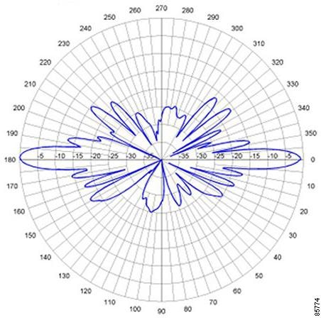
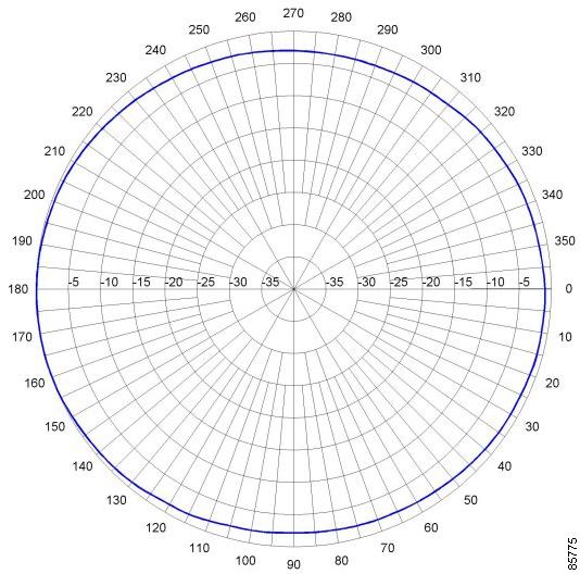
This document outlines the specifications and description of the 12-dBi high gain omnidirectional antenna. This antenna operates in the 2400-2500 MHz band and is designed for use outdoors. The antenna is compatible with Cisco Aironet radio products utilizing a reverse-polarity TNC (RP-TNC) connector.
The following information is provided in this document:
•
Obtaining Documentation and Submitting a Service Request
Technical Specifications
System Requirements
This antenna is designed for use with Cisco Aironet access points and bridges but can be used with any 2.4-GHz Cisco Aironet radio device that uses a reverse-polarity threaded naval connector (RP-TNC).
Installation Notes
Choosing a Mounting Location
The antenna is designed to create an omni-directional broadcast pattern. To achieve this pattern, the antenna should be mounted clear of any obstructions to the sides of the radiating element. If the mounting location is on the side of a building or tower, the antenna pattern will be blocked on the building or tower side.
Tools and Equipment Required
To install the antenna, you will need the following tools and equipment.
•
•
The following sections contain procedures for installing the antenna. Choose the procedure that applies to your situation. Use Figure 1 as a guide.
Mounting the Antenna
The antenna is provided with a mounting kit. This kit allows you to mount the antenna to masts up to three inches in diameter. The antenna is vertically polarized. Since the antenna has vertical gain, it is very important to mount the antenna in a vertical (not leaning) position for optimal performance.
Follow these steps to mount the antenna to a mast.
Step 1
Step 2
Step 3
Step 4
Step 5
Step 6
Step 7

Note
Figure 1 Antenna Mount Assembly
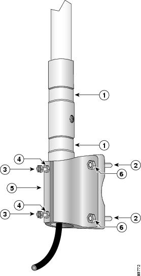
Antenna grooves
Jam nuts
5/16 x 18 U-bolt
Sandcast bracket
1/4-20 hex bolts
5/16-18 hex nut
Suggested Cable
Cisco recommends a high-quality, low-loss 50-ohm cable for use with the antenna, such as those listed in
Table 1.
Note
The antenna terminates with a special connector (reverse-TNC plug) after a short, 1-ft. cable. The mating connector to the antenna is an appropriate reverse-TNC jack connector. The connector on the opposite end varies according to the type of equipment used.
After the cable is attached to the antenna, make sure that the connections are sealed (if using outdoors) to prevent moisture and other weathering elements from affecting performance.
Note
Cisco recommends using a coax seal for outdoor connections. Silicon sealant or electrical tape are not recommended for sealing outdoor connections.
The final step is to attach the antenna to your wireless device.
Safety Precautions

Warning
Each year hundreds of people are killed or injured when attempting to install an antenna. In many of these cases, the victim was aware of the danger of electrocution, but did not take adequate steps to avoid the hazard.
For your safety, and to help you achieve a good installation, please read and follow these safety precautions. They may save your life!
1.
2.
3.
4.
5.
a.
b.
c.
6.
7.
If an accident should occur with the power lines call for qualified emergency help immediately.
Obtaining Documentation and Submitting a Service Request
For information on obtaining documentation, submitting a service request, and gathering additional information, see the monthly What's New in Cisco Product Documentation, which also lists all new and revised Cisco technical documentation, at:
http://www.cisco.com/en/US/docs/general/whatsnew/whatsnew.html
Subscribe to the What's New in Cisco Product Documentation as a Really Simple Syndication (RSS) feed and set content to be delivered directly to your desktop using a reader application. The RSS feeds are a free service and Cisco currently supports RSS Version 2.0.
Cisco and the Cisco Logo are trademarks of Cisco Systems, Inc. and/or its affiliates in the U.S. and other countries. A listing of Cisco's trademarks can be found at www.cisco.com/go/trademarks. Third party trademarks mentioned are the property of their respective owners. The use of the word partner does not imply a partnership relationship between Cisco and any other company. (1005R)

 Feedback
Contact Cisco
- Open a Support Case

- (Requires a Cisco Service Contract)
This Document Applies to These Products
- Collaboration Endpoints - Retired Products
- Conferencing - Retired Products
- Contact Center - Retired Products
- Optical Networking - Retired Products
- Routers - Retired Products
- Security - Retired Products
- Servers - Unified Computing (UCS) Retired Products
- Storage Networking Retired Products
- Switches - Retired Products
- Video - Retired Products
- Wireless - Retired Products