Deployment Models
Available Languages
Table Of Contents
Multisite Centralized Call Processing Model
Multisite Distributed Call Processing Model
Cisco Unified Communications Manager Session Management Edition
Cisco Intercompany Media Engine
Clustering Over IP WAN Call Processing Model
Major Components of Deployment Models
Deployment Models
This chapter provides an overview of the Cisco Unified Communications deployment models that Cisco has tested and verified. These models are not the only ways in which you can deploy the Cisco Unified Communications system, nor are they design recommendations. Rather, they are designed to provide sample configurations that address typical system-level requirements.
For additional guidelines, recommendations, and best practices for implementing enterprise networking solutions, refer to the Cisco Solution Reference Network Design (SRND) guides and related documents, which are available at this URL:
http://www.cisco.com/go/designzone
For additional information about the deployment models, including details about all components in each model, refer to the Cisco Unified Communications System Technical Information site at: http://www.cisco.com/go/unified-techinfo.
This chapter includes these sections:
•
Multisite Centralized Call Processing Model
•
•
•
Deployment Overview
The sample Cisco Unified Communications deployments demonstrate a variety of business applications based on the following criteria:
•
•
•
•
•
•
•
•
•
Single-Site Model
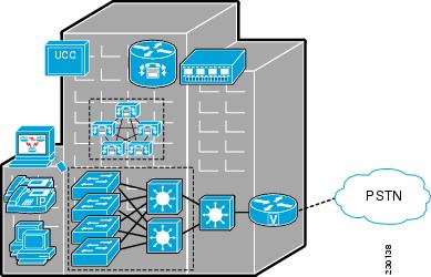
The Single-Site model is designed for autonomous offices in which most or all employees are IPC users. This model supports up to 30,000 users.
Figure 2-1 shows an example of this model.
Figure 2-1 Single-Site Model
Organization Suitability
The Single-Site model is suitable for medium-sized businesses and government operations that reside at one site and that need basic call processing, some contact center capabilities, and basic messaging and conferencing. Such operations include legal and financial professional offices, and municipal government offices.
Design Characteristics
The Single-Site model is designed to be locally managed and administered. It can operate on a wired or wireless LAN. Local and long distance calling is achieved through gateway connectivity with the PSTN by various combinations of T1/E1 CAS and PRI.
User Roles and Endpoints
The Single-Site model provides flexible communications features for operators and administrative assistants. There are some executive phones, some of which are video-capable. Most other employees use digital telephones, including wireless telephones, and a voice messaging system, which this model also provides. In addition, some staff may take orders or provide technical support. This model provides basic contact center capabilities to handle these requirements.
Some users, such as building services and shipping and receiving employees, may require mobile phones. This model provides on-campus device mobility features for these users.
Supported Applications
The Single-Site model supports applications that provide a wide array of advanced features. These applications include:
•
–
–
–
•
–
–
–
–
•
–
–
–
•
•
–
–
•
–
–
–
–
–
IPv6 support
The Cisco Unified Communications System support the deployment of IPv6 in Unified Communications products. The characteristics and benefits of the IPv6 single-site model is the same as those for IPv4 single-site deployments. However, the IPv6 single-site model includes the additional IPv6 and dual-stack product capabilities and features
For more information, see the Cisco Unified Communications Solution Reference Network Design (SRND), available at:
http://www.cisco.com/go/designzone
Multisite Centralized Call Processing Model
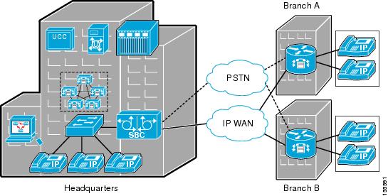
The Multisite Centralized Call Processing model is designed for distributed operations with a large central or headquarters site and multiple remote or branch sites. This model can support up to a total of 30,000 phones distributed among up to a maximum of 1000 sites. Based upon the bandwidth available, each site can support any number of users up to the overall total of 30,000 phones.
Figure 2-2 shows an example of this model.
Figure 2-2 Multisite Centralized Call Processing Model
Organization Suitability
The Multisite Centralized Call Processing model is suitable for businesses such as banks, which include a corporate headquarters and many local or regional offices.
Design Characteristics
In the Multisite Centralized Call Processing model, each branch site connects to the headquarters site or sites through a WAN. Branch sites receive call processing functions from the headquarters site. Failover capabilities at each branch site ensure that it can continue to operate if the WAN connection to the headquarters site is lost. Branch sites include small contact center capabilities.
The WAN connection between the headquarters and branch sites can be frame relay, MPLS, or site-to-site VPN. Each branch site can operate on a wired or wireless LAN.
Connectivity with legacy PBXs in the headquarters site can be provided T1/E1 CAS, PRI, Q SIG, and DPNSS. Connectivity to the PSTN in the headquarters site is provided through various combinations of T1/E1 CAS and PRI.
Local calling is achieved through gateway connectivity. Long distance calling for branch sites uses the WAN for on-net calling. Off-net long distance traffic is backhauled over the WAN to one or more drop-off gateways.
This model is designed to be administered at the headquarters location.
User Roles and Endpoints
Headquarters roles and endpoints are identical to those described in the "Single-Site Model" section. Branch sites access the call processing capabilities in the headquarters site. While there are some executive phones, most employees use digital telephones and the central voice messaging system.
Some staff may take orders or provide technical support. This model provides basic contact center capabilities in the branches to handle these requirements.
Supported Applications
The Multisite Centralized Call Processing model supports applications that provide comprehensive features for all sites. These applications include:
•
–
–
–
–
•
–
–
–
–
•
–
–
–
•
•
–
–
•
–
–
–
–
–
Multisite Distributed Call Processing Model
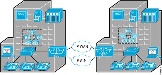
The Multisite Distributed Call Processing model is designed for organizations with large user populations or large numbers of geographically distributed sites resulting in the need for more than a single call processing entity. This model is suited for deployments that require multiple Cisco Unified Communications Manager clusters or Cisco Unified Communications Manager Express platforms. Each call processing entity in this model is configured as a Single-Site Model (see the "Single-Site Model" section) or Multisite Centralized Call Processing Model (see the "Multisite Centralized Call Processing Model" section) and each has a common dial plan and feature set. Each site has its own call processing agent cluster connected to an IP WAN that carries voice traffic between the distributed sites.
The multisite distributed call processing model supports up to 30,000 SCCP or SIP IP phones or video endpoints per cluster.
Figure 2-3 shows an example of this model.
Figure 2-3 Multisite Distributed Call Processing Model
Organization Suitability
The Multisite Distributed Call Processing model is suitable for business operations that consist of multiple sites in various regions. Such operations include technology, manufacturing, transportation, and distribution and logistics companies.
Design Characteristics
Each site in the Multisite Distributed Call Processing model can operate on a wired or wireless LAN. The intersite WAN connection can be frame relay, MPLS, or site-to-site VPN. Each branch site can operate on a wired or wireless LAN.
Local calling is achieved through gateway connectivity at each site. Long distance calling for each site uses the WAN for on-net calling. Off-net long distance traffic is backhauled over the WAN to one or more drop-off gateways.
User Roles and Endpoints
Each site in the Multisite Distributed Call Processing model has the same user roles and endpoints that are described in the "Multisite Centralized Call Processing Model" section.
Supported Applications
The Multisite Distributed Call Processing model supports applications that provide powerful, flexible, and scalable features. These applications include:
•
–
–
–
–
•
–
–
–
•
–
–
–
•
•
–
–
•
–
–
–
–
–
IPv6 support
The Cisco Unified Communications System support the deployment of IPv6 in Unified Communications products. The characteristics and benefits of the IPv6 multi-site WAN deployment with distributed call processing model is the same as those for IPv4 multi-site WAN deployment with distributed call processing deployments. However, the IPv6 multi-site WAN deployment with distributed call processing model includes the additional IPv6 and dual-stack product capabilities and features.
For more information, see the Cisco Unified Communications Solution Reference Network Design (SRND), available at:
http://www.cisco.com/go/designzone
Cisco Unified Communications Manager Session Management Edition
Unified communications deployments using Cisco Unified Communications Manager Session Management Edition is a variation of the multisite distributed call processing deployment model and is typically employed to interconnect large numbers of unified communications systems through a single front-end system, in this case the Unified Communications Manager Session Management Edition.
Unified Communications Manager Session Management Edition may also be used to connect to third-party unified communications systems such as IP PSTN connections, PBXs, and centralized unified communications applications. However, as with any standard Unified Communications Manager cluster, third-party connections to Unified CM Session Management Edition must be tested for interoperability prior to use in a production environment.
Figure 2-4 shows an example of this model.
Figure 2-4 Multisite Deployment with Unified CM Session Management Edition

Unified CM Session Management Edition can be deployed if you want to:
•
•
•
For additional information on the deployment models, refer to the Cisco Solution Reference Network Design (SRND) guides and related documents available at:
http://www.cisco.com/go/designzone
Cisco Intercompany Media Engine
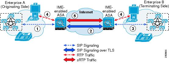
Cisco Intercompany Media Engine (Cisco IME) is a variation of a multisite deployment with distributed call processing, but with Cisco IME, the sites are separate enterprise organizations. The Cisco IME will route a call that would normally be sent over a PSTN trunk over the public internet. The solution learns routes in a dynamic, secure manner and provides for secure communications between organizations across the internet. Organizations that work closely together and have high levels of intercompany communications will benefit most from the enhanced communications offered by Cisco IME.
This deployment is configured with two independent Unified CM clusters interconnected via PSTN and public internet, which supports bi-directional calling using Cisco IME as well as simultaneously placing and receiving calls to non-Cisco IME sites over WAN and PSTN.
The Cisco IME deployment is supported on Unified CM 8.x and later versions or Unified CM Session Management Edition 8.x and later.
The Cisco IME components deployed are:
•
•
•
Unified CM communicates with Cisco IME servers to upload the Cisco IME designated directory numbers to the distributed cache ring and sends call records to Cisco IME for PSTN calls made by these directory numbers. Unified CM also receives Cisco IME learned routes that are validated by the Cisco IME servers and initiates dynamic SIP trunk calls to the remote directory numbers in these Cisco IME learned routes. SIP trunk signaling always flows through a Cisco IME-enabled Adaptive Security Appliance (ASA), which provides perimeter security for the solution.
Once the Cisco IME learned route is stored in the Unified CM database, the information in the route is used to set up a Cisco IME call. However, the Cisco IME server is not involved in the call processing phase. To initiate a Cisco IME call, the called number should match the Cisco IME learned route pattern in the database and the directory number of the calling phone should be enrolled in Cisco IME. Then, Unified CM dynamically invoke a Cisco IME SIP trunk to the external IP address or fully qualified domain name of the terminating enterprise.
A Cisco IME enabled ASA serves as a proxy for all Cisco IME communications with remote organizations. The ASA provides network address translation (NAT) and SIP application layer gateway (ALG) functionality to translate addressing inside the SIP messaging itself.
Figure 2-5 provides a high level view of the Cisco IME call processing.
Figure 2-5 Cisco Intercompany Media Engine Call Processing
For additional information on Cisco IME deployment, refer to the Cisco Intercompany Media Engine section in the Unified Communications Deployment Models chapter of Unified Communications SRND at: http://www.cisco.com/go/designzone
Clustering Over IP WAN Call Processing Model
The Clustering Over IP WAN Call Processing model is designed for organizations with large user populations across multiple sites that are connected by an IP WAN with the QoS features enabled. The Clustering Over IP WAN supports the two deployment models:
•
Local failover requires that you place the Unified Communications Manager subscriber and backup servers at the same site, with no WAN between them. This deployment model is ideal for two to four sites with Unified Communications Manager.
•
Remote failover allows you to deploy primary and backup call processing servers split across the WAN. Using this deployment model, you may have up to eight sites with Unified Communications Manager subscribers being backed up by Unified Communications Manager subscribers at another site.
You can also use a combination of the two deployment models to satisfy specific site requirements. For example, two main sites may each have primary and backup subscribers, with another two sites containing only a primary server each and utilizing either shared backups or dedicated backups at the two main sites.
Organization Suitability
The Clustering Over IP WAN Call Processing model is suitable for business operations that consist of multiple sites in various regions connected over an IP WAN. Such operations include technology, manufacturing, transportation, and distribution and logistics companies.
Design Characteristics
The local failover and remote failover sites in the Clustering Over IP WAN Call Processing model operates over an IP WAN. The intersite WAN connection can be frame relay, MPLS, or site-to-site VPN.
The IP WAN must conform to the following maximum delay and minimum bandwidth requirements:
•
•
•
The IP WAN network should also be engineered to provide sufficient prioritized bandwidth for all ICCS traffic, especially the priority ICCS traffic. Standard QoS mechanisms must be implemented to avoid congestion and packet loss. If packets are lost due to line errors or other conditions, the ICCS packet will be retransmitted because it uses the TCP protocol for reliable transmission. The retransmission might result in a call being delayed during setup, disconnect (teardown), or other supplementary services during the call.
For additional details on IP WAN delay, bandwidth requirements, and QOS engineering, refer to the Clustering Over the IP WAN section in the Unified Communications Deployment Models chapter of Unified Communications SRND at: http://www.cisco.com/go/designzone
User Roles and Endpoints
The local failover and remote failover sites in the Clustering Over IP WAN Call Processing model has the same user roles and endpoints that are described in the "Multisite Centralized Call Processing Model" section.
Some of the key advantages of clustering over the WAN are:
•
•
•
•
•
Supported Applications
The Clustering Over IP WAN Call Processing model supports applications that provide powerful, flexible, and scalable features. These applications include:
•
–
–
–
•
–
–
–
•
–
–
–
•
•
–
–
•
–
–
–
–
–
Major Components of Deployment Models
Table 2-1 shows the major Cisco components in each Cisco Unified Communications deployment model.
 Feedback
Contact Cisco
- Open a Support Case

- (Requires a Cisco Service Contract)
This Document Applies to These Products
- Collaboration Endpoints - Retired Products
- Conferencing - Retired Products
- Contact Center - Retired Products
- Optical Networking - Retired Products
- Routers - Retired Products
- Security - Retired Products
- Servers - Unified Computing (UCS) Retired Products
- Storage Networking Retired Products
- Switches - Retired Products
- Video - Retired Products
- Wireless - Retired Products