Network Management Tools Configuration
Available Languages
Table Of Contents
Network Management Tools Configuration
Cisco Unified Operations Manager
Configuring IP Telephony Components for Monitoring
Configuring Cisco Unified Operations Manager for Each Component
CiscoWorks Resource Manager Essentials
Network Management Tools Configuration
This chapter provides an overview of how two network management tools, Cisco Unified Operations Manager and CiscoWorks Resource Manager Essentials, were configured during Cisco Unified Communications Release 5.0(2) testing for IP telephony systems. It describes the deployed test environment, but does not contain detailed installation and configuration instructions.
For detailed information about installing, configuring, and administering Cisco Unified Operations Manager and CiscoWorks Resource Manager Essentials, refer to the documents shown in Table 19-1.
Table 19-1 Cisco Unified Operations Manage and CiscoWorks Resource Manager Essentials Documentation
Cisco Unified Operations Manager
General Unified Operations Manager documentation
http://www.cisco.com/en/US/products/ps6535/
tsd_products_support_series_home.htmlInstallation Guide for Cisco Unified Operations Manager 1.1
http://www.cisco.com/en/US/products/ps6535/
products_installation_guide_book09186a008063c22a.htmlQuick Start Guide for Cisco Unified Operations Manager 1.1
http://www.cisco.com/en/US/products/ps6535/
products_quick_start09186a0080627fa3.htmlUser Guide for Cisco Unified Operations Manager 1.1
http://www.cisco.com/en/US/products/ps6535/
products_user_guide_book09186a0080639558.htmlCiscoWorks Resource Manager Essentials
General Resource Manager Essentials documentation
http://www.cisco.com/en/US/products/ps6509/tsd_products_support_series_home.html
Installation and Setup Guide for Resource Manager Essentials 4.0.3 on Windows (With LMS 2.5.1)
Installation and Setup Guide for Resource Manager Essentials 4.0.3 on Solaris (With LMS 2.5.1)
User Guide for Resource Manager Essentials 4.0.3 (With LMS 2.5.1)
http://www.cisco.com/en/US/products/sw/cscowork/ps2073/products_user_guide_book09186a008055b137.html
Cisco Unified Operations Manager
The Cisco Unified Operations Manager provides a consolidated view of the entire Cisco Unified Communications infrastructure and presents the current operational status of each element in the network. It continuously monitors the current operational status of various Cisco components. The Cisco Unified Operations Manager also provides diagnostic capabilities for faster trouble isolation and resolution.
For Cisco Unified Communications Release 5.0(2) system testing, Cisco Unified Operations Manager was installed on a Cisco MCS-7845 in the Very Large Campus with Clustering over the WAN site model. The Cisco Unified Operations Manager server was configured to monitor components at this site as well as remotely monitor components at other sites. The types of devices monitored during testing included:
•
Cisco routers, including Unified SRST routers
•
•
•
•
•
•
•
•
Customized polling groups and thresholds for the groups were configured according to the instructions in the Cisco Unified Operations Manager documentation. Figure 19-1 shows the Monitoring Dashboard window of the Cisco Unified Operations Manager administration interface used to monitor the test network.
Figure 19-1 Cisco Unified Operations Manager Administration Interface
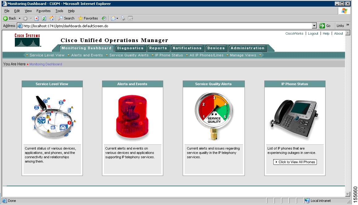
During system testing, the Monitoring Dashboard functions appearing on this window were used as follows:
•
•
•
•
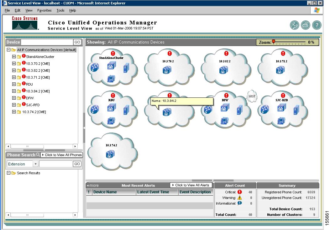
Figure 19-2 shows the System Level View for several sites in the test network, including several SRST sites.
Figure 19-2 Service Level View Example
Configuring IP Telephony Components for Monitoring
Cisco Unified Operations Manager uses Simple Network Management Protocol (SNMP) to collect statistics and status information from various Cisco components in the network. Each Cisco component must be configured with the Cisco Unified Operations Manager as an SNMP notification destination, so that the component will forward SNMP traps to the Cisco Unified Operations Manager for monitoring. For example, on IOS-based routers and switches in the system test environment, the following configuration commands were included:
snmp-server community public ROsnmp-server system-shutdownsnmp-server enable traps snmp authentication linkdown linkup coldstart warmstartsnmp-server enable traps ttysnmp-server host 10.9.12.21 version2In the test environment. 10.9.12.21 was the IP address of the Cisco Unified Operations Manager server.
For instructions on configuring the Cisco Unified Operations Manager server as an SNMP destination (sometimes referred to as a "trap receiver") for some Cisco components, seeTable 19-2.
Table 19-2 Cisco Documentation for Setting SNMP Notification Destinations
Cisco Unified CallManager Release 5.0 servers1
Cisco Unified CallManager Serviceability Administration Guide, Release 5.0(2), "SNMP V1/V2c Configuration" or "SNMP V3 Configuration" chapters
http://www.cisco.com/en/US/products/sw/voicesw/ps556/products_administration_guide_chapter09186a008062a996.htmlCisco Unified CallManager Release 4.1(2) servers
Cisco Unified CallManager Serviceability Administration Guide, Release 4.1(2), "Simple Network Management Protocol Configuration" chapter
http://www.cisco.com/en/US/products/sw/voicesw/ps556/products_administration_guide_chapter09186a00802de94b.htmlCisco Unity2
Cisco Unity Maintenance Guide (With Microsoft Exchange), Release 4.0(5), "Configuring Cisco Unity for Maintenance Tasks" chapter
http://www.cisco.com/en/US/products/sw/voicesw/ps2237/products_maintenance_guide_chapter09186a008044381c.htmlCisco Unity Express
Cisco Unity Express 2.2 System Monitoring Guide, "Configuring System Monitoring for Cisco Unity Express" chapter
http://www.cisco.com/en/US/products/sw/voicesw/ps5520/prod_troubleshooting_guide_chapter09186a00804cc405.html#wp1057987Cisco Emergency Responder
Cisco Emergency Responder Administration Guide 1.3(1), "Administration Web Interface For Cisco Emergency Responder 1.3(1)" appendix
http://www.cisco.com/en/US/products/sw/voicesw/ps842/products_administration_guide_chapter09186a00806173f1.html#wp1006155Cisco Unified MeetingPlace
Administrator's Guide for Cisco MeetingPlace Audio Server Release 5.3, "Cisco MeetingPlace SNMP" appendix
http://www.cisco.com/en/US/products/sw/ps5664/ps5669/products_administration_guide_chapter09186a00803339cd.htmlCisco Unified MeetingPlace Express
Administrator's Configuration and Maintenance Guide for Cisco MeetingPlace Express Release 1.1, "Maintaining the Cisco MeetingPlace Express System" chapter
http://www.cisco.com/en/US/products/ps6533/products_administration_guide_chapter09186a0080579e27.htmlCisco Unified MobilityManager
Cisco Unified MobilityManager Administration Guide, Release 1.2, "System Configuration" chapter
http://www.cisco.com/en/US/products/ps6567/products_administration_guide_chapter09186a0080646073.html#wp1069220
1 When configuring the public community string on the Cisco Unified CallManager Serviceability SNMP Community String Configuration window, make certain you assign ReadWriteNotify access privileges to the string so that it can be replicated on all nodes in the Cisco CallManager cluster. Also, verify that the Cisco CallManager SNMP Service is activated on all Unified CallManager servers in the cluster.
2 If you are integrating Cisco Unity with IBM Lotus Domino or using a different version of Cisco Unity, see http://www.cisco.com/en/US/products/sw/voicesw/ps2237/prod_maintenance_guides_list.html for the appropriate Cisco Unity Maintenance Guide.
Configuring Cisco Unified Operations Manager for Each Component
The Cisco Unified Operations Manager application runs on top of a CiscoWorks Common Services platform. CiscoWorks Common Services are bundled with Cisco Unified Operations Manager software and automatically installed as part of the Cisco Unified Operations Manager installation.
In order for a device to be monitored by the Cisco Unified Operations Manager, you must first enter its credentials in the CiscoWorks Common Services Device and Credentials Repository (DCR) by accessing the Common Services administration window and choosing Devices and Credentials > Device Management.

Note
Figure 19-3 shows the standard credentials dialog box used to enter device credentials and enable communication between the device and the Cisco Unified Operations Manager.
Figure 19-3 Cisco Unified Operations Manager Standard Credentials
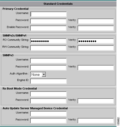
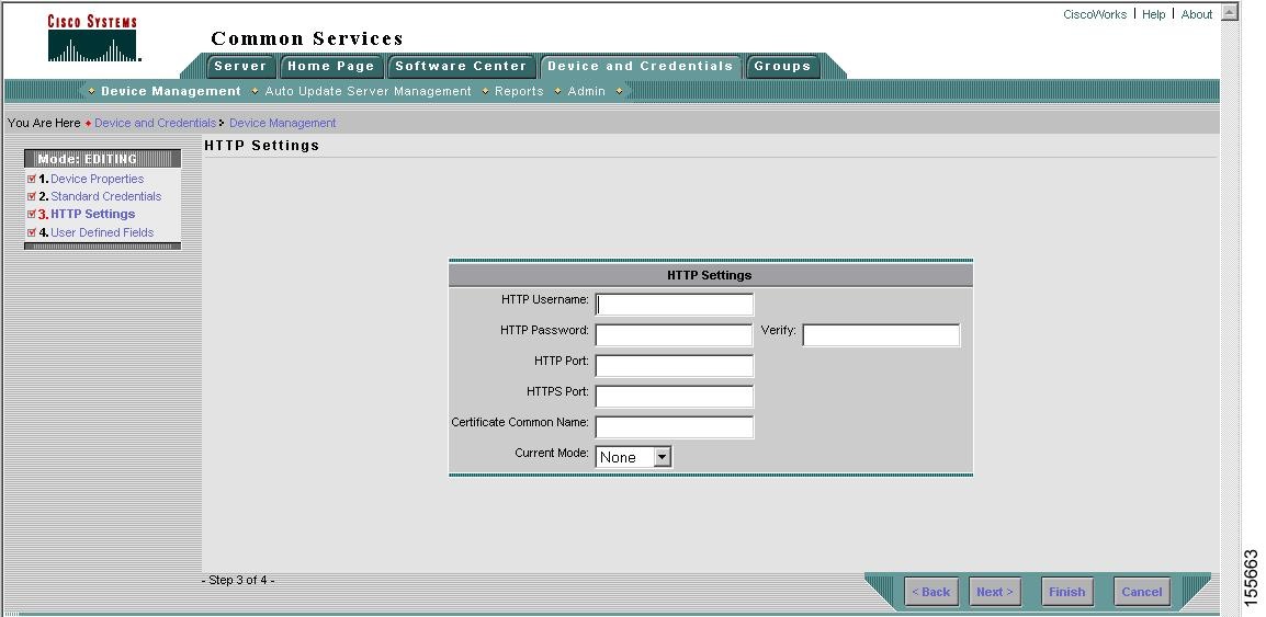
For IOS-based devices, you must supply Telnet login information and public community strings. For devices that provide a Web browser-based administration interface (such as Cisco Unified CallManager), you must also configure HTTP settings using the dialog box shown in Figure 19-4.
Figure 19-4 Cisco Unified Operations Manager HTTP Settings
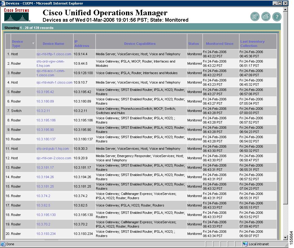
After the device credentials are successfully entered, you can view a list of all devices monitored by the Cisco Unified Operations Manager as shown in Figure 19-5. If the device does not appear, verify the credentials you entered.
Figure 19-5 Cisco Unified Operations Manager Sample Device List
Monitoring Alert Example
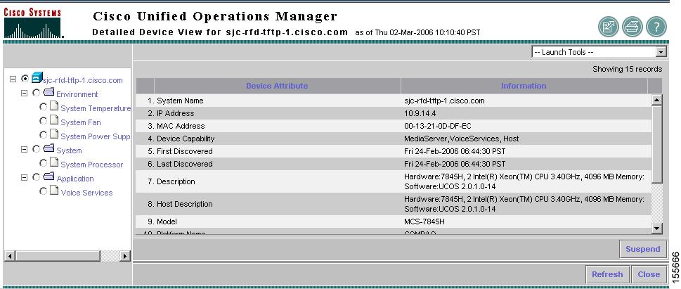
Figure 19-6 shows an example of alerts generated when one or more services running on a Cisco Unified CallManager go down. For a particular device, you can view all alerts currently being reported by the device and then obtain a detailed device view to see the configuration of that device, as shown in Figure 19-7.
Figure 19-6 Cisco Unified Operations Manager Alert Example
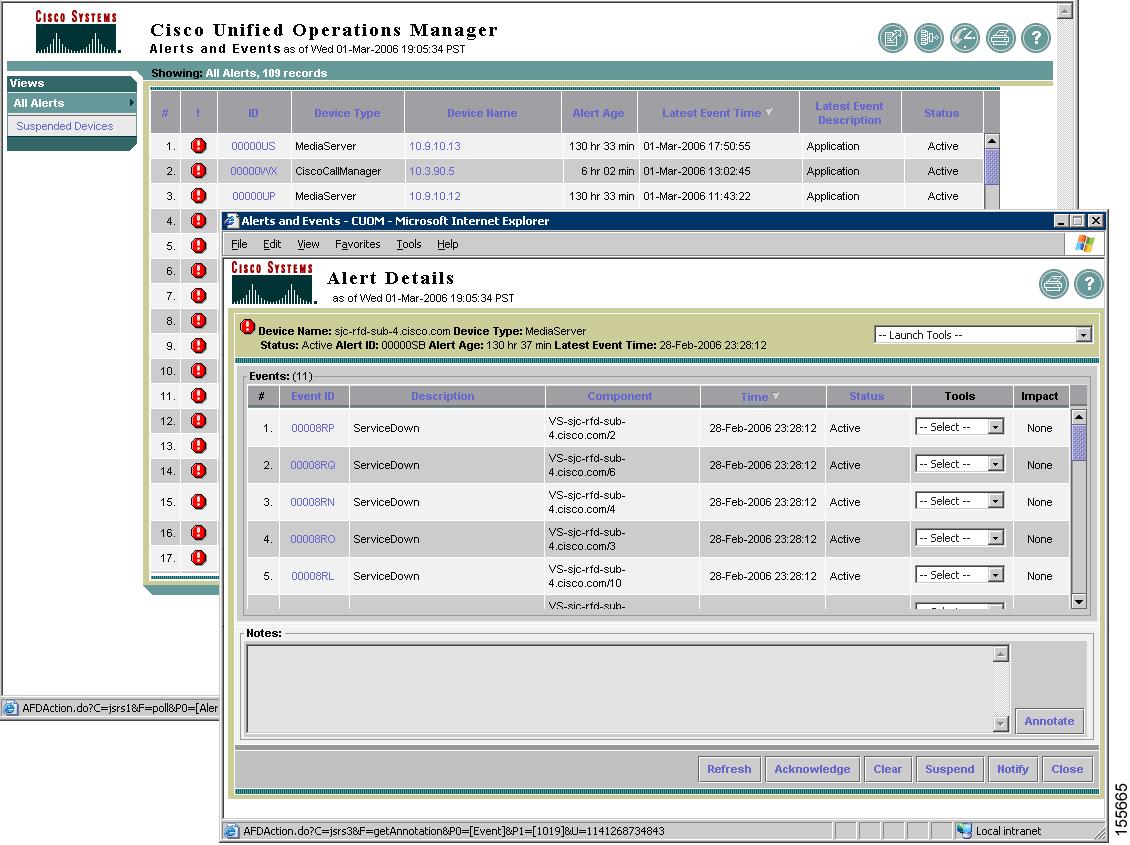
Figure 19-7 Cisco Unified Operations Manager Detailed Device View
CiscoWorks Resource Manager Essentials
CiscoWorks Resource Manager Essentials (RME) allows network administrators to view and update the status and configuration of all Cisco devices from anywhere on the network through a standard Web browser as the Resource Manager Essentials client. In addition, Resource Manager Essentials automatically records any changes made to network devices, making it easy to identify when changes are made and by whom. During Cisco Unified Communications Release 5.0(2) testing, Resource Manager Essentials was used to perform software upgrades on the following tested devices:
•
•
•
•
The Resource Manager Essentials application runs on top of a CiscoWorks Common Services platform. Prior to installing Resource Manager Essentials, CiscoWorks Common Services must first be installed and configured on the server. For CiscoWorks installation and configuration instructions, see the references in Configuring Cisco Unified Operations Manager for Each Component.
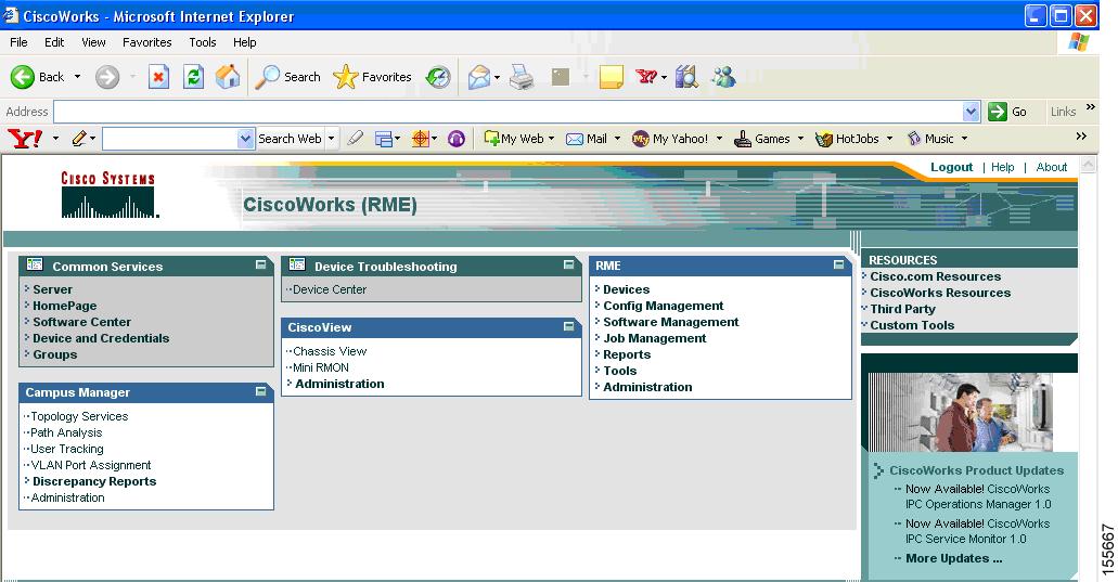
Figure 19-8 shows the main window of the Resource Manager Essentials administration interface.
Figure 19-8 CiscoWorks Resource Manager Essentials Administration Interface
Before you can upgrade devices using Resource Manager Essentials, you must first import software images into the Resource Manager Essentials platform by choosing Software Management > Software Depository as shown in Figure 19-10.
Figure 19-9 Resource Manager Essentials Software Repository Management
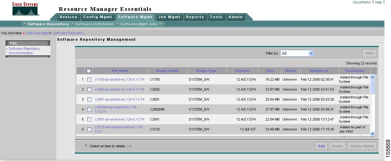
In order for IOS-based routers and switches to accept software updates from Resource Manager Essentials, the following commands must appear in their configuration:
SNMP-server community public ROSNMP-server community private RWSNMP-server system-shutdownSNMP-server enable traps snmp authentication linkdown linkup coldstart warmstartsnmp-server enable traps ttysnmp-server host 10.9.22.34 version2In this example, the IP address 10.9.22.34 is the IP address of the Resource Manager Essentials server. Note that the devices must allow both SNMP read and write capability (RW) to allow the Resource Manager Essentials server to write the new image to the device.
To upgrade devices in your network, choose Software Management > Software Distribution and select the devices to upgrade. For each device, you can select the image to download (the latest image is selected by default) as shown in Figure 19-10.
Figure 19-10 Resource Manager Essentials Software Distribution
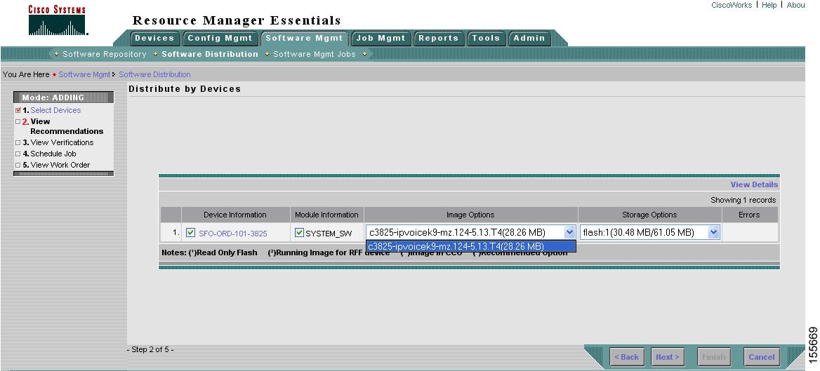
While deploying the image, you must select the option to reboot the device after uploading to boot the new image. Also, you can choose to back up the running image in order to quickly change back to an earlier image if the new image does not perform as expected.
 Feedback
Contact Cisco
- Open a Support Case

- (Requires a Cisco Service Contract)
This Document Applies to These Products
- Collaboration Endpoints - Retired Products
- Conferencing - Retired Products
- Contact Center - Retired Products
- Optical Networking - Retired Products
- Routers - Retired Products
- Security - Retired Products
- Servers - Unified Computing (UCS) Retired Products
- Storage Networking Retired Products
- Switches - Retired Products
- Video - Retired Products
- Wireless - Retired Products