Cisco Unity and Unity Connection Configuration
Available Languages
Table Of Contents
Cisco Unity and Unity Connection Configuration
Cisco Unity Administration Settings
Cisco Unity Integration with IBM Lotus Domino
Cisco Unity Connection Configuration
Unity Connection Testing in North America Site Models
Multiple Phone System Integration Testing with Unity Connection in EUEM Site Models
Unified CallManager Express Integration with Cisco Unity Connection
IP-to-IP Gateway Integration with Cisco Unity Connection
Cisco Unified CallManager Configuration to Support Cisco Unity and Unity Connection
Cisco Unity and Unity Connection Configuration
This chapter provides an overview of how Cisco Unity and Cisco Unity Connection were configured during Cisco Unified Communications Release 5.0(2) testing for IP telephony systems. This chapter does not include detailed installation and configuration instructions. Rather, it is intended to provide you with guidance and serve as a reference model as you set up the Cisco Unity or Cisco Unity Connection component of your IP telephony system.
Cisco Unity and Cisco Unity Connection were configured according to the instructions in the their documentation. In general, default or recommended configuration values were used. For detailed information about installing, configuring, administering and upgrading Cisco Unity and Cisco Unity Connection, see the documents listed in Table 3-1.
This chapter includes the following sections:
•
Cisco Unity Connection Configuration
•
Table 3-1 Cisco Unity and Cisco Unity Connection Documentation
Cisco Unity
General Cisco Unity documentation
http://www.cisco.com/en/US/products/sw/voicesw/ps2237/tsd_products_support_series_home.html
Cisco Unity Documentation Addendum, Release 4.2
http://www.cisco.com/univercd/cc/td/doc/product/voice/c_unity/unity42/index.htm
Installation Guide for Cisco Unity Unified Messaging with Microsoft Exchange 2003/2000 (With Failover Configured), Release 4.0(5) and Later
Installation Guide for Cisco Unity Unified Messaging with Microsoft Exchange 2003/2000 (Without Failover), Release 4.0(5) and Later
Installation Guide for Cisco Unity Unified Messaging with IBM Lotus Domino (With Failover Configured), Release 4.0(5) and Later
Installation Guide for Cisco Unity Unified Messaging with IBM Lotus Domino (Without Failover), Release 4.0(5) and Later
Cisco Unity Reconfiguration and Upgrade Guide (With Microsoft Exchange)
Cisco Unity Reconfiguration and Upgrade Guide (With IBM Lotus Domino)
Multiple Phone System Integration Guide for Cisco Unity 4.2 and Later
http://www.cisco.com/en/US/products/sw/voicesw/ps2237/prod_configuration_guide09186a00806192a3.html
Cisco Unity Connection
General Cisco Unity Connection documentation
http://www.cisco.com/en/US/products/ps6509/tsd_products_support_series_home.html
Cisco Unity Connection Installation Guide, Release 1.x
http://www.cisco.com/en/US/products/ps6509/
products_installation_guide_book09186a00805201e8.htmlCisco Unity Connection Administration and Call Management Guide, Release 1.x
http://www.cisco.com/en/US/products/ps6509/
products_administration_guide_book09186a00805201b8.htmlCisco Unified CallManager 5.0 SCCP Integration Guide for Cisco Unity Connection 1.1
http://www.cisco.com/en/US/products/ps6509/prod_configuration_guide09186a008061aaf3.html
Cisco Unified CallManager 5.0 SIP Trunk Integration Guide for Cisco Unity Connection 1.1
http://www.cisco.com/en/US/products/ps6509/prod_configuration_guide09186a008061ab46.html
Multiple Phone System Integration Guide for Cisco Unity Connection 1.1
http://www.cisco.com/en/US/products/ps6509/prod_configuration_guide09186a00805672bd.html
Cisco Unity Configuration
In the North America site models, Cisco Unity and Microsoft Exchange 2003 were installed on the following servers running Windows 2000 Server operating system:
•
•
•
•
For information on how Unity testing was performed for EUEM site models, see Cisco Unity Integration with IBM Lotus Domino.
Cisco Unity Topology
The following figures show how Cisco Unity was set up for various site models:
•
•
–
–
–
Figure 3-1 Cisco Unity Logical Topology
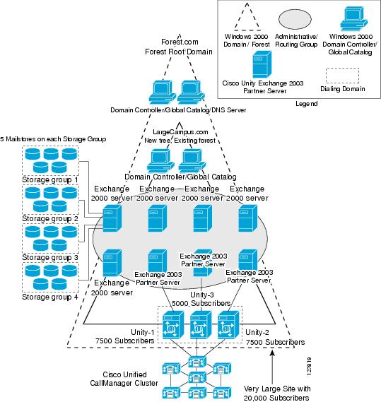
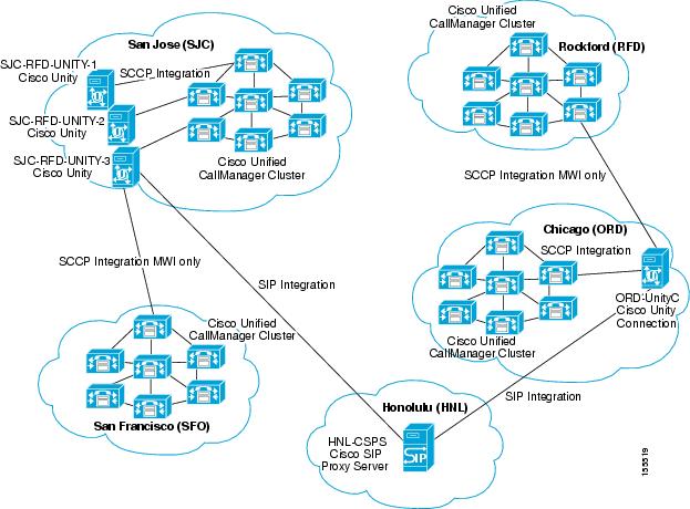
Figure 3-2 Cisco Unity and Unity Connection Physical Topology
Cisco Unity Administration Settings
As shown in Figure 3-2, three Cisco Unity servers were located in the SJC site and primarily served subscribers spread across the SJC and RFD sites. Figure 3-3 illustrates the Cisco Unity Administration settings for the Cisco Unified CallManager clustered servers managing these two sites.
Figure 3-3 Cisco Unity Server Configuration for Clustered Unified CallManager Servers

One of the three Cisco Unity servers in SJC was configured for multiple cluster integration, integrated to both the SJC-RFD Unified CallManager cluster as well as the SFO-ORD Unified CallManager cluster. This integration allows the Cisco Unity server in SJC to provide voice mail services for a few subscribers in the SFO and ORD sites. Figure 3-4 shows the Cisco Unity Administration settings to support integration with the SFO-ORD Unified CallManager cluster.
Figure 3-4 Cisco Unity Server Configuration for SFO-ORD Unified CallManager Cluster
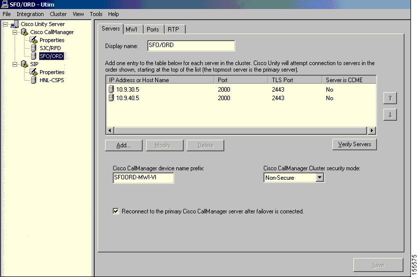
On the Unified CallManager servers for the SJC-RFD cluster, this Cisco Unity server was assigned to the device pool named DP_CM1_2. The settings for this device pool are provided in the "System > Device Pool" section.
For subscribers located in SFO or ORD that have voice mail boxes on Cisco Unity servers in SJC, the voice path for recording a voice message and the Message Waiting Indicator (MWI) signaling path are different. For example, when someone calls Subscriber A in SFO and the phone is busy or there is no answer, the call is forwarded over an ICT to the Unity server in SJC and the message recorded. However, once the message is recorded, the MWI from the Unity server in SJC is sent directly to the subscriber's phone in SFO using the SCCP integration enabled for MWI only. In order for this configuration to work, the Multiple Tenant MWI Modes service parameter must be set to True on the Unified CallManager cluster controlling the subscriber's phone (in this case, the SFO-ORD cluster).
The same Cisco Unity server was also configured for dual integration (serving both SCCP and SIP endpoints) with a Cisco SIP Proxy Server located at the HNL site. Figure 3-5 shows the server entry in Cisco Unity Administration for the Cisco SIP Proxy Server and Figure 3-6 shows the SIP-specific parameters for integration between a Unity Server and Cisco SIP Proxy Server.

Note
Figure 3-5 Cisco Unity Server Configuration for Cisco SIP Proxy Server
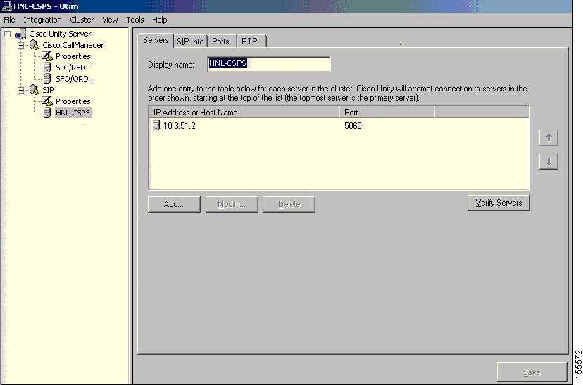
Figure 3-6 Cisco Unity Configuration for SIP Integration to Cisco SIP Proxy Server

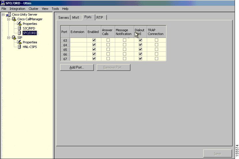
The voice mail ports on this Cisco Unity server were allocated to sites as follows:
•
•
•
Figure 3-7 shows the Cisco Unity Administration configuration for some of the ports allocated to the SFO and ORD sites.
Figure 3-7 Unity Server Voice Mail Port Configuration
The other two Cisco Unity servers in SJC were only integrated to the SJC-RFD Unified CallManager cluster and each server allocated 72 voice mail ports to these sites. One server was integrated to device pool DP_CM3_4 and the other to device pool DP_CM5_6.
In the tested configuration, subscribers were not able to call into individual voice mail ports because these ports were assigned to a partition named SJC_Unity_pt that was not accessible to any other devices. Instead, a set of pilot numbers (22100, 22200 and 22300) were configured to hunt for the available voice mail ports.
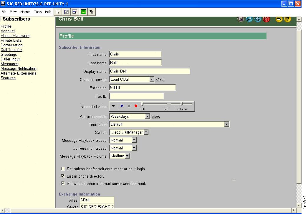
Figure 3-8 shows the profile settings for an example of a subscriber provisioned on the Cisco Unity servers in SJC. Configurations for subscribers in SFO were the same for subscribers in SJC; no special subscriber configuration is required for multiple cluster integration. The subscriber settings are also identical for both SCCP and SIP Cisco Unified IP Phones.
Figure 3-8 Cisco Unity Configuration for a Subscriber
Cisco Unity Integration with IBM Lotus Domino
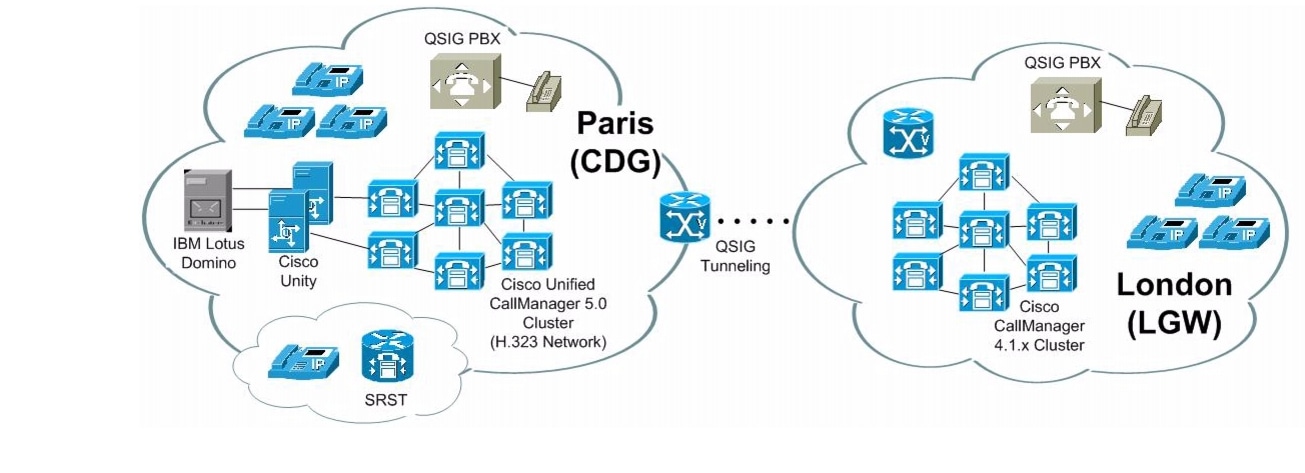
In the EUEM test environment, Cisco Unity was installed on a pair of MCS-7845-H1-ECS1 servers in a failover configuration in the Large Multi-Site Centralized with SRST site model. Although Cisco Unity is typically integrated to a Cisco Unified CallManager cluster using SCCP, during Cisco Unified Communications Release 5.0(2) testing in EUEM it served as the voice mail system for the following phone systems through QSIG trunks:
•
•
•
For all three phone systems, Cisco Unity used a standalone IBM Lotus Domino server as the message store. Figure 3-9 illustrates the EUEM test environment for Cisco Unity testing.
Note
Figure 3-9 Cisco Unity Setup in EUEM Test Environment
Using G.711 and G.729 codecs over Ethernet, ATM and Frame Relay networks, test calls to Cisco Unity subscribers were originated from several different origination points including:
•
•
•
•
Supplementary manuals are available that describe how to integrate IBM Lotus Domino with Cisco Unity, such as the Cisco Unity Reconfiguration and Upgrade Guide (With IBM Lotus Domino) which provides upgrade instructions if you are upgrading from a previous IP Communications Systems Test release; see Table 3-1 for more information.
Cisco Unity Connection Configuration
Cisco Unity Connection is similar to Cisco Unity except in the following aspects:
•
•
•
•
Unity Connection was tested on both the North America and EUEM site models during Cisco Unified Communications Release 5.0(2) system testing.
Unity Connection Testing in North America Site Models
Similar to the Cisco Unity server in SJC, the Cisco Unity Connection server in ORD was configured for multiple cluster integration, integrated to both the SJC-RFD Unified CallManager cluster as well as the SFO-ORD Unified CallManager cluster. The settings for Unified CallManager clusters that must be configured on Cisco Unity Connection servers are very similar to those shown in the previous section, although the Cisco Unity Connection Administration graphical interface appears slightly different.
Figure 3-10 the basic settings for an example of a user provisioned on the Cisco Unity Connection server in ORD. Similar to Cisco Unity, no special user configuration is required for multiple cluster integration for Unity Connection. The user settings are also identical for both SCCP and SIP Cisco Unified IP Phones.
Figure 3-10 Cisco Unity Connection Setup for a Subscriber

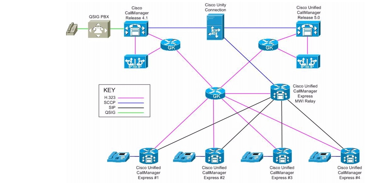
Multiple Phone System Integration Testing with Unity Connection in EUEM Site Models
We validated multiple integration using SCCP protocol. Details of configurations are on the following link : http://www.cisco.com/univercd/cc/td/doc/product/voice/uconn/integuid/multuc11.htm
Unity connection needs to have multiple SCCP trunk to the different Phones Systems. This is one major difference with Unity multiple integration.
Unity Connection will be the voice mail system for multiple Phone systems. UnityConnection will have trunk to connect :
- a cluster running Cisco Call Manager 5.X release
- a cluster running Cisco Call Manager 4.X release
- a group of Cisco Call Manager express using a MWI relay server to Unity Connection
- QSIG PBX that were connecting to CCM clusters
Figure 3-11 Unity Connection Test Topology for Multiple Phone System Integration
Unified CallManager Express Integration with Cisco Unity Connection
In case of integrating multiple CME, a MWI relay server is used to send unsolicited SIP notify messages to CMES.
We are going to detail a portion of the CME configuration that was specific to our configuration. The problematic we have to resolve was that Phones were defined on unity connection and for call routing with their On-net extension which is a 7 digits extension. However the phone should display the local extension which is a 4 digits extension.
The following is used to enable SIP on CME :
voice service voipallow-connections h323 to h323allow-connections sip to sipsupplementary-service h450.12redirect ip2ipfax protocol t38 ls-redundancy 0 hs-redundancy 0 fallback noneh323call start slowsipbind control source-interface Loopback0bind media source-interface Loopback0the following were added to tell the CME that he msut use a MWI relay server for MWI notification. 10.10.130.91 is the MWI relay server in our case
sip-uamwi-server ipv4:10.10.130.91 expires 3600 port 5060 transport tcpthe following will enable voice mail integration on CME
telephony-service
voicemail 7141700
the phones were configured suing the following :
ephone-dn 1 dual-linenumber 8336600 secondary 6600 no-reglabel 6600description 0191 765 6600call-forward noan 7141700 timeout 10mwi sipEvery phones are defined on Unity Connection by their 7 digits extension. In the network, the 7 digits are needed to route the call.
In this specific configuration, we wanted the 7 digit number to be registered to the gatekeeper but the short number (4 digits) to appear on the phone display. So we use Label command to display the correct number on the phone. We also use the no-reg command to prevent the short number to be registered on the gatekeeper. The mwi sip command will advertise the first number (the 7 digits number) to the MWI relay server.
For additional information on Cisco Unified CallManager Express and MWI relay server configuration, see "Cisco Unified CallManager Express Integration with Cisco Unity Express, Unity, and Unified CallManager Using IP-to-IP Gateways".
IP-to-IP Gateway Integration with Cisco Unity Connection
In some scenario, we have some issues when the inbound call was answered by Unity Connection, but while Unity Connection was trying to transfer the call, the call was cleared.
Phone A > CCM1 > IP-IP GW1> GK > IP-IP GW2> CCM2 > Unity Connection. For some call scenario, there is one message "send TCS" that is not supported by IP-IP gateway which was clearing the call. However CCM in terminating leg needed to know which version is running CCM1 to not send this forbidden message. The h245 passthru tcsnonstd-passthru needs to be enable on all IP-IP gateway.
Configuration for the IP-IP gateway :
voice service voipallow-connections h323 to h323supplementary-service h450.12fax protocol t38 ls-redundancy 0 hs-redundancy 0 fallback noneh323emptycapabilitycall start slowh245 passthru tcsnonstd-passthruFor additional information on IP-to-IP Gateway testing performed during Cisco Unified Communications Release 5.0(2) system testing, see the "Integrating Cisco Unified CallManager Express with Unified CallManager Through IP-to-IP Gateways" section.
Cisco Unified CallManager Configuration to Support Cisco Unity and Unity Connection
On the SJC-RFD Unified CallManager cluster in the North America deployment, the Cisco Unity server voice mail ports were assigned to a calling search space named SJC_Unity_css which had full access to the PSTN and other clusters; see the "Call Routing > Class of Control > Calling Search Space" section for the partitions assigned to this calling search space.
Three voice mail pilot numbers were configured on the SJC-RFD Unified CallManager cluster. To access the Cisco Unified CallManager Administration web pages for adding and configuring voice mail pilots, choose Voice Mail > Voice Mail Pilot from the Cisco Unified CallManager Administration application.
Table 3-2 describes the settings in the Voice Mail Pilot Configuration page for the three voice mail pilot numbers.
To support voice mail, the following important Cisco Unified CallManager settings in must be configured on the directory number assigned to the phone/line:
•
•
•
Table 3-3 shows how a sample directory number was configured for voice mail in the Directory Number Configuration page, with the important settings highlighted. To access the Cisco Unified CallManager Administration web pages for adding and configuring directory numbers, choose Call Routing > Directory Number from the Cisco Unified CallManager Administration application. When configuring directory numbers for voice mail, you should be aware that:
•
•
•
Table 3-4 describes the settings in the Voice Mail Profile Configuration page for the VoiceMail1 profile shown in the previous table.
For additional voice mail configuration settings in Cisco Unified CallManager Administration, see the "Cisco Unified CallManager Voice Mail Configuration" section.
 Feedback
Contact Cisco
- Open a Support Case

- (Requires a Cisco Service Contract)
This Document Applies to These Products
- Collaboration Endpoints - Retired Products
- Conferencing - Retired Products
- Contact Center - Retired Products
- Optical Networking - Retired Products
- Routers - Retired Products
- Security - Retired Products
- Servers - Unified Computing (UCS) Retired Products
- Storage Networking Retired Products
- Switches - Retired Products
- Video - Retired Products
- Wireless - Retired Products