Configure High Availability for Unified CVP

Server Groups

A Server group is a dynamic routing feature that enables the originating endpoint to have knowledge of the status of the destination address before attempting to send the SIP INVITE. Whether the destination is unreachable over the network, or is out of service at the application layer, the originating SIP user agent can have fore-knowledge of the status through a heartbeat mechanism.

The Server Groups add a heartbeat mechanism with endpoints for SIP. This feature enables faster failover on call control by eliminating delays due to failed endpoints.

The following list is a summary of important configuration items:

  • Server Groups are not automatically added to your configuration. You must explicitly configure Server Groups for their deployment and turn on this feature.

  • If you have already configured the local SRV feature and therefore created a srv.xml file, you must run the srvimport.bat command before you configure Server Groups using the Operations Console. Otherwise, your existing definitions will be overwritten. This process is explained in the configuration details that follow.

  • You define Server Groups using the Operations Console. You must always configure at least one Call Server first, because you will not be able to save the Server Groups configuration without assigning it to at least one Call Server.

Configure Server Groups

Complete the following steps to configure Server Groups:

  1. If you have previously created an srv.xml file, after you upgrade your Unified CVP installation, run the batch file srvimport.bat to transfer your prior configuration to the new Server Groups feature.

    The srvimport.bat file is located in the CVP bin directory. This batch file takes your srv.xml file as an argument. Copy this file from your Call Server configuration directory. Running srvimport.bat brings this configuration data into the Operations Console.


    Note


    You must stop the OAMP (Operations Console) service before you run the .bat file.
  2. If you have not defined a Call Server using the Operations Console, refer to Configuring a Call Server in the Operations Console online help.

  3. From the Operations Console, click System > SIP Server Groups > Add New SIP Server Group.

  4. A Server Group consists of one or more destination addresses (endpoints) and is identified by a Server Group domain name. This domain name is also known as the SRV cluster name, or Fully Qualified Domain Name (FQDN). Define the FQDN and add it to the list. Refer to Configuring Server Groups in the Operations Console online help.

  5. Refer to SIP Server Group Configuration Settings in the Operation Console online help to complete the Server Group configuration.

  6. Click the Call Server Deployment tab and select the Call Server(s) that you want to associate with the Server Group(s). Then click Save & Deploy .


    Note


    When you associate the Call Server(s) configuration, all the SIP Server Group configurations are applied to the Call Server(s), but individual deployment of SIP Server Group is not supported.


Server Groups Diagnostics

The CVP log file has traces which show endpoint status events. From the diagnostic servlet, click on the link for dump SIP state machine to display information as shown in the following example:
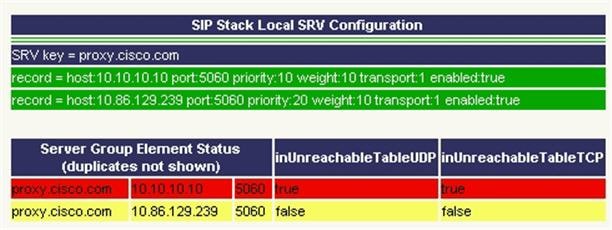
Figure 1. Server Group Diagnostics


Redundancy and Failover for Unified CVP

This section describes redundancy and failover mechanisms for ASR, TTS, Media, and VXML Servers in the Unified CVP solution.

Redundancy for VXML Server Applications

VXML Server applications rely on the gateway’s configured default for ASR and TTS servers, which allow only a single host name or IP address to be specified for each. This differs from the Unified CVP micro-applications based applications, which support automatic retries to specifically named backup ASR and TTS servers.

Use the following configuration on the gateway if you are using Nuance or Scansoft ASR/TTS servers:


                            ip host asr-en-us 10.10.10.1
                            ip host tts-en-us 10.10.10.2
                        

Use the following configuration on the gateway if you are using Nuance or Scansoft ASR/TTS servers:


                            mrcp client rtpsetup enable
                            ivr asr-server rtsp://asr-en-us/recognizer
                            ivr tts-server rtsp://tts-en-us/synthesizer
                            http client cache memory pool 15000
                            http client cache memory file 500
                            ivr prompt memory 15000
                            ivr prompt streamed none
                            mrcp client timeout connect 5
                            mrcp client timeout message 5
                            rtsp client timeout connect 10
                            rtsp client timeout message 10
                            vxml tree memory 500
                            http client connection idle timeout 10
                            no http client connection persistent
                        

The URL configured by the above ivr commands defines the gateway's default target for ASR and TTS services, and is in effect for all calls handled by that gateway. You can override it dynamically in your VXML Server application by populating the Cisco-proprietary VoiceXML properties com.cisco.asr-server or com.cisco.tts-server.

Redundancy for Micro-App-Based Applications

When a load balancer is used for ASR or TTS servers, the IVR Service plays a significant role in implementing a failover mechanism for Media Servers, ASR/TTS Servers and micro-app-based applications. Up to two of each such servers are supported, and the IVR Service orchestrates retries and failover between them.


Note


This redundancy mechanism is only available for Unified CVP micro-applications.

Note


For information about setting up the IVR Service to accommodate failover, see the Administration Guide for Cisco Unified Customer Voice Portal.

IVR Service Failover Mechanism

The IVR Service failover mechanism applies to:

  • Connections between the IVR Service and the IOS Voice Browser, only.

  • All communication between the IOS Voice Browser and an ASR Server, TTS Server, or Media Server.

  • Media Server, when the ICM Script ECC variable, user.microapp.media_server, is set to mediaserver. When user.microapp.media_server is set to mediaserver, the IVR Service uses the IP Address defined on the gateway as:

    • ip host mediaserver 10.86.129.50

    • ip host mediaserver-backup 10.86.129.51


    Note


    If user.microapp.media_server is configured as the hard-coded IP Address of the media server, then the IVR Service will not perform any failover for the media server.

If the IVR Service receives a Call Result error code value of 9 (MEDIA_FILE_NOT_FOUND), 33 (GENERAL_ASR_TTS), 31 (MEDIA_RESOURCE_ASR) or 32 (MEDIA_RESOURCE_TTS), it does the following:

  • When attempting to connect to a Media Server , the IVR Service:

    • Resends the request the number of times defined in the IVR Service Configuration's Media Server Retry Attempts field.

    • If the connection is not successful after the specified number of attempts, and the IVR Service Configuration's Use Backup Media Servers field is set to Yes (the default), the IVR Service makes the same number of attempts to retrieve the media from a backup media server before failing and generating an error.


      Note


      The backup media server is defined on the gateway as <mediaserver>-backup.
    • Passes the error in a Call State Event to the ICM Service, which then passes it to Unified ICME.

  • When attempting to connect to an ASR/TTS Server, the IVR Service:

    • Resends the request the number of times defined in the IVR Service Configuration's ASR/TTS Server Retry Attempts field.

    • If the connection is not successful after the specified number of attempts, and the IVR Service Configuration's Use Backup ASR/TTS Servers field is set to Yes (the default), the IVR Service makes the same number of attempts to connect to a backup ASR/TTS server before failing and generating an error.


      Note


      The backup ASR and TTS servers are defined on the gateway as asr-<locale>-backup and tts-<locale>-backup.
    • Passes the error in a Call State Event to the ICM Service, which then passes it to Unified ICME.

Each new call attempts to connect to the primary server. If failover occurs, the backup server is used for the duration of the call; the next new call will attempt to connect to the primary server.


Note


This failover mechanism differs from that used in prior releases of Unified CVP software. Legacy releases used a sticky connection. In a sticky connection, if failover occurs to a backup server, subsequent new calls automatically connect to the backup server, rather than attempt to connect with the primary server.

If the Unified CVP IVR Service fails, the following conditions apply to the call disposition:

  • Calls in progress are default-routed to an alternate location on the originating gateway. (Survivability does not apply in NIC-routing models.)

  • New calls are directed to an in-service Unified CVP IVR Service.

ASR and TTS Server Location Setup

There are two ways to specify an external media server for TTS and ASR operations:


Note


While using ASR/TTS, use a single version of MRCP (v1/v2) instead of using it in mixed mode.


Specify an ASR and TTS Server Location Globally on the Gateway

Media server sessions are created for each call to IVR applications, regardless of whether an application needs to communicate with the media server. Follow these steps to specify an ASR and TTS server location globally on the gateway.

Procedure


Step 1

Define the Hostname to IP Address mapping for the ASR and TTS servers.

ip host asr-en-us 10.78.26.31
ip host tts-en-us 10.78.26.31

Step 2

Define the Voice class URI that matches the SIP URI of the ASR Server in the dial-peer.

voice class uri TTS sip
pattern tts@10.78.26.31

Step 3

Define the Voice class URI that matches the SIP URI of TTS server in the dial-peer. Syntax - voice class uri tag sip.

voice class uri ASR sip
pattern asr@10.78.26.31

Step 4

Define the SIP URI of the ASR and TTS Server. Syntax -sip:server-name@host-name | ip-address.

ivr asr-server sip:asr@10.78.26.31
ivr tts-server sip:tts@10.78.26.31

Step 5

Set up a SIP VoIP dial-peer that is an outbound dial-peer when the Gateway initiates an MRCP over SIP session to the ASR server.

dial-peer voice 5 voip
session protocol sipv2
destination uri ASR
dtmf-relay rtp-nte
codec g711ulaw
no vad

Step 6

Set up a SIP VoIP dial-peer that is an outbound dial-peer when the Gateway initiates an MRCP over SIP session to the TTS server.

dial-peer voice 6 voip
session protocol sipv2
destination uri TTS
dtmf-relay rtp-nte
codec g711ulaw
no vad

Step 7

Specify the name or IP address of a SIP server; usually a proxy server. You can then configure the dial-peer session target as session target sip-server. Syntax - sip-server {dns:[host-name] |ipv4: ip-addr[:port-num]}.

sip-ua
sip-server ipv4:10.78.26.31

Specify an ASR and TTS Server Location with an Individual VoiceXML Document

Media server sessions occur for each call to that application. If only a small number of applications require TTS/ASR media sessions, use the <property> extensions within those applications to define the external media server URL in the VoiceXML script.


Note


Specifying the URL of media servers in a VoiceXML document takes precedence over the gateway configuration. Any value that is configured on the gateway is ignored if the same attribute is configured with a VoiceXML property.


com.cisco.tts-server

The “com.cisco.tts-server” allows the document to specify an external media server for text-to-speech operations. The media server is specified in the form of an URI, and is used in all consecutive TTS operations until the next media server is specified. An external media server specified by a property in the script takes precedence over being specified by a command through the CLI.

It can be defined for:

  • An entire application or document at the <vxml> level

  • A specific dialog at the form or menu level

  • A specific form item

You can format the media server URI for Media Resource Control Protocol version 1 (MRCP v1), which uses Real Time Streaming Protocol (RTSP), IP Address or Hostname; or MRCP v2, which uses Session Initiation Protocol (SIP), IP Address or Hostname for example:

<property name="com.cisco.tts-server" value="rtsp://tts-server1/synthesizer" />

<property name="com.cisco.tts -server" value="sip:mresources@mediaserver.com" />

<property name="com.cisco.tts-server" value=“10.10.10.10" />

<property name="com.cisco.tts-server" value=“ttsserver.com" />

com.cisco.asr-server

The “com.cisco.asr-server” allows the document to specify an external media server for recognize operations. The media server is specified in the form of an URI, and is used in all consecutive ASR operations until the next media server is specified. An external media server specified by a property in the script takes precedence over being specified by a command through the CLI.

You can format the media server URI for Media Resource Control Protocol version 1 (MRCP v1), which uses Real Time Streaming Protocol (RTSP), IP Address, or Hostname, or MRCP v2 which uses Session Initiation Protocol (SIP), IP Address or Hostname for example:

<property name="com.cisco.asr-server" value="rtsp://asr-server/synthesizer" />

<property name="com.cisco.asr -server" value="sip:mresources@mediaserver.com" />

<property name="com.cisco.asr-server" value=“10.10.10.10" />

<property name="com.cisco.asr-server" value=“asrserver.com" />

Set Up the VoiceXML Document Properties

Procedure

Step 1

In Unified Call Studio, view the properties for the AgeIdentification.

Step 2

Specify the VoiceXML document properties at either the root or node level.

Step 3

Select Properties > General Settings > Language, and specify “en–us” as the language.

Certain third-party software and hardware are compatible only with US English.


Example Gateway Configuration for MRCPv2 with Failover

-----------------Primary Server-----
ip host asr-en-us 10.78.26.83
ip host tts-en-us 10.78.26.83
ivr asr-server sip:asr@asr-en-us
ivr tts-server sip:tts@tts-en-us

voice class uri ASR sip
pattern asr@asr-en-us*
voice class uri TTS sip
pattern tts@tts-en-us*

dial-peer voice 5 voip
destination uri ASR
session target ipv4:10.78.26.83
session protocol sipv2
dtmf-relay rtp-nte
codec g711ulaw
no vad

dial-peer voice 6 voip
destination uri TTS
session target ipv4:10.78.26.83
session protocol sipv2
dtmf-relay rtp-nte
codec g711ulaw
no vad

-------Backup --------------------
dial-peer voice 7 voip
destination uri ASR
session target ipv4:10.78.26.20
session protocol sipv2
dtmf-relay rtp-nte
codec g711ulaw
preference 2
no vad

dial-peer voice 8 voip
destination uri TTS
session target ipv4:10.78.26.20
session protocol sipv2
dtmf-relay rtp-nte
codec g711ulaw
preference 2
no vad