Unified CVP Call Flow Models

Standalone Call Flow Model

Call Flow for the Unified CVP VXML Server (Standalone) Call Flow Model using VXML Gateway

In this call flow model, the VXML Server is a J2EE-compliant server that provides a complete solution for rapidly creating and deploying dynamic VoiceXML applications. You can install the VXML Server as a standalone component without the Unified CVP Call Server component and with or without the Reporting.

The following table lists the required and optional Unified CVP components needed for the Standalone call flow model:

Table 2. Required and Optional Unified CVP Components for Standalone Call Flow Model

CVP components

Related topics

Required CVP components

VXML Server

Ingress Gateway

VoiceXML Gateway

Cisco VVB

Operations Console

Operations Console

Call Server

Media Servers

Media Server Configuration

Optional CVP components

Reporting Server

Reporting Server Configuration

Speech Servers

Speech Server Configuration

Unified ICM Enterprise

Unified ICM Configuration

The Unified CVP VXML Server (Standalone) call flow model is available in the following variations:

  • Standalone without reporting: Use the VXML Server (Standalone) option in the Operations Console. This call flow model does not require a Call Server and a Reporting Server.

  • Standalone with reporting: Use the VXML Server option in the Operations Console. This call flow model requires a Call Server and a Reporting Server.

  • Standalone, but adding reporting after the VXML Server (Standalone) version has already been configured: Configure the Unified CVP Call Server, delete the VXML Server (Standalone), and use the VXML Server option in the Operations Console to add the VXML Server.

See VXML Server Configuration for configuration instructions.

In this call flow model with reporting, the Unified CVP Call Server is used to route messages between the components. Calls arrive through a VoiceXML gateway and interact directly with a VXML Server to run VoiceXML applications. The gateway performs both ingress and VoiceXML functions. This call flow model provides a sophisticated VoiceXML-based VRU, for applications which, in many cases, do not need to interact with a Unified ICME Server.

In the Unified CVP VXML Server (standalone) call flow model, only the VXML Server, Call Studio, and a Gateway are required, except when using reporting which requires a Call Server and a Reporting Server.

This standalone model has functions similar to the VRU-Only Call Flow Model with NIC Routing.


Note


The CVP VXML standalone call flow model allows only one synchronous blind or bridged transfer. A synchronous blind transfer indicates that once the call has been transferred, a Unified CVP Standalone script has no ability to asynchronously take it back and deliver it somewhere else, whereas Unified ICME scripts, in the Unified ICME-integrated models, do have that ability.

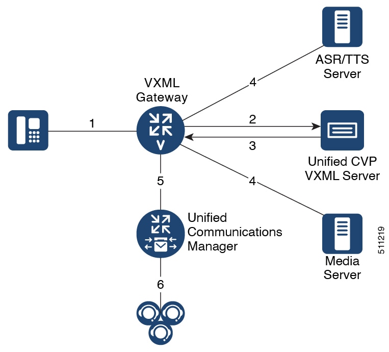
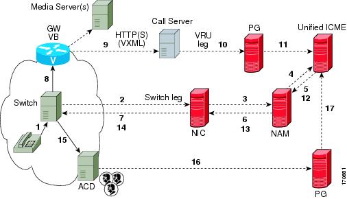
The following figure displays the call flow for the Unified CVP VXML Server (standalone) call flow model using VXML Gateway.

Figure 1. Call Flow for the Unified CVP VXML Server (Standalone) Call Flow Model using VXML Gateway


The following, numbered, call flow description for the previous figure assumes:

  • You installed and licensed the VXML Server.

  • You created a Call Studio application and deployed it on the VXML Server.

The call flow shown in the previous figure is as follows:

  1. The call arrives from the PSTN network to the Gateway.

  2. The Gateway sends an HTTP URL request to the VXML Server.

  3. The VXML Server returns the VoiceXML instructions to be run on the VXML Gateway.

  4. The VoiceXML instructions returned to the Gateway can include references to ASR/TTS to recognize voice input and play TTS files, and references to Media Servers to play .wav files.

  5. The gateway can, optionally, transfer the call to any destination that it can deliver a call to, such as Unified CM.

  6. Unified CM can then send the call to an agent.

Call Flow for the Unified CVP VXML Server (Standalone) Call Flow Model using Cisco VVB

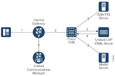
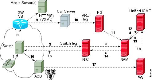
The following figure displays the call flow for the Unified CVP VXML Server (standalone) call flow model using Cisco VVB.

Figure 2. Call Flow for the Unified CVP VXML Server (Standalone) Call Flow Model using Cisco VVB


  1. The call arrives from the PSTN network or the service provider to the Ingress Gateway or Cisco Unified Border Element (CUBE).

  2. The Gateway sends an SIP invite to Cisco VVB with the trigger number configured in Cisco VVB for the Self Service application.

  3. Cisco VVB sends an HTTP URL request to the VXML Server.

  4. The VXML Server returns the VoiceXML instructions to be run on Cisco VVB.

  5. The VoiceXML instructions returned to Cisco VVB can include references to ASR/TTS to recognize voice inputs and play TTS files, and references to the media servers to play .wav files.

  6. The Gateway can, optionally, transfer the call to any destination that it can deliver a call to, such as the Unified CM.

  7. The Unified CM can then send the call to an agent.

Configure VXML Server Standalone Call Flow Model

The following steps apply to all variations of standalone call flow model:

Procedure


Step 1

Configure the gateway for VXML Server (Standalone) applications:

  1. Define the VXML Server applications on the gateway.

    Note


    Backup server is optional. For the Tomcat Application Server, set the port to 7000. The backup server cannot be the same server as the Primary Server.

  2. Configure the base gateway and Cisco VVB settings.

    For gateway settings, see the Example: Gateway Settings for Standalone Call Flow Model.

    For Cisco VVB settings, see the Configure Cisco VVB Settings for Standalone Call Flow Model.

  3. Configure the service settings on the gateway.

    See the Example: Gateway Settings for Standalone Call Flow Model.

  4. Configure a dial-peer, which will call the service to reach the Unified CVP VXML Server.

    See the Example: Dial-Peer for Standalone Call Flow Model with VXML Gateway.

  5. (Optional) Create additional dial-peers for any outgoing transfer destinations your application uses.

Review the updated gateway configuration by issuing the show run command to examine the running configuration.

Step 2

Create an application using Call Studio and deploy it as a zip file.

For information about Unified Call Studio, see the User Guide for Cisco Unified CVP VXML Server and Unified Call Studio.


Enable Reporting for Standalone Call Flow Model

Procedure

Step 1

Follow steps 1 and 2 from Configure VXML Server Standalone Call Flow Model.

Step 2

Enable loggers on the Call Studio.

See the User Guide for Cisco Unified CVP VXML Server and Unified Call Studio for details on configuring loggers using Call Studio.

Step 3

Configure the Call Server.

For more information on configuring a Call Server, see Configure Call Server

Step 4

Configure the VXML Server.

  1. In the Operations Console, select Device Management > VXML Server and add a VXML Server with an associated Primary Call Server.

  2. To enable reporting for this VXML Server, in the Operations Console, select the Configuration tab and select Enable Reporting for this VXML Server.

  3. Add appropriate filtering.

For more information on configuring a VXML Server, see the Configure VXML Server section.

Step 5

Click Save and Deploy.

Step 6

Deploy the Call Studio application on the VXML Server.

Note


By default, CVPSNMPLogger is enabled when a new Call Studio application is created and deployed to the VXML Server.

Step 7

Configure the Reporting Server.

  1. In the Operations Console, select Device Management > CVP Reporting Server > General tab and configure the Reporting Server.

  2. Select a Call Server to associate with this Reporting Server.

  3. Check the default values of the Reporting properties and change, if desired.

For more information, see the Reporting Guide for Cisco Unified Customer Voice Portal available at https://www.cisco.com/c/en/us/support/customer-collaboration/unified-customer-voice-portal/products-user-guide-list.html.

Step 8

Click Save and Deploy.


Enable ICM Lookup for Standalone Call Flow Model

Procedure


Step 1

Follow steps 1 and 2 from Configure VXML Server Standalone Call Flow Model.

Step 2

Use the ReqICMLabel element in the Call Studio script as a decision element.

The ReqICMLabel element has two exit states: error and done. The done path must connect to a transfer element to transfer the caller to ReqICMLabel as referenced by the ReqICMLabel Element.

For information about Unified Call Studio, see the User Guide for Cisco Unified CVP VXML Server and Unified Call Studio.

Step 3

Enable loggers on the Call Studio.

See the User Guide for Cisco Unified CVP VXML Server and Unified Call Studio for details on configuring loggers using Call Studio.

Step 4

Configure the Call Server and enable the ICM Service.

For more information on configuring a Call Server, see the Configure Call Server.

Step 5

Configure the VXML Server.

For more information on configuring a VXML Server, see the Configure VXML Server section.

Step 6

Deploy the Call Studio application on the VXML Server.

Note


By default, CVPSNMPLogger is enabled when a new Call Studio application is created and deployed to the VXML Server.

Step 7

Using the ICM Script Editor, create a Unified ICME script that returns a label.

In order to transfer information from Unified ICME to the VXML Server besides the label, use the ToExtVXML0 - 4 ECC Variables and Peripheral Variables 1 - 10. The format for using the ToExtVXML 0 - 4 is with name value pairs that are delimited by semi-colons.

Example:

ToExtVXML0 = "company=Cisco Systems;state=MA".

Use the Peripheral Variables 1 - 10 to pass information to the VXML Server. The values in the variables are taken as is.

For more information about creating a Unified ICME script that returns a label in, see the Unified ICME documentation.

For more information about using the ReqICMLabel element, see the Pass Data to Unified ICME.


Comprehensive Call Flow Model

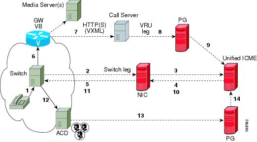
The Comprehensive call flow model is deployed where the Unified CVP acts as a switch or is deployed at the Network Application Manager (NAM) to act as a switch. The call flow models to deploy these scenarios are listed in the Comprehensive Call Flow Model for ICME and Comprehensive Call Flow Model for ICMH sections. In these call flow models, a call can have two legs one with the Ingress Gateway and other with the Cisco VVB:
  • Switch leg: For the Switch leg, the Gateway provides Gateway capabilities from TDM to VoIP and call-switching capabilities

  • VRU leg: For the VRU leg, the VXML Gateway provides VRU voice treatment.


    Note


    Unified ICMH sees these as a single call routed through different peripherals for different purposes.


The SIP calls using the Unified CVP micro-applications use the IVR Service of Call Server that has the switch leg of the call. VoiceXML fetches are sent to the Call Server. The VoiceXML traffic for micro-applications must return only to the same Call Server as the switch leg.

Sending VoiceXML traffic to multiple application servers is implemented in Unified CVP 4.0(1) onwards by extracting the IP address of Call Server from the SIP signaling messages in the bootstrap service rather than using static configuration in the service parameter for the bootstrap servicesound of VoiceXML Gateway.

The Comprehensive call flow model extracts the Call Server host from the SIP signaling. The Unified CVP SIP Service is handling the switch legs of the call. If you make a SIP call that does not involve the switch leg with Unified CVP, the service parameters below applies for the VRU leg only. Comprehensive calls always use the same Call Server for both switch leg and VRU legs. Using the same Call Server simplifies the solution and makes it easier to troubleshoot and debug.


Note


The app-info header parameter is for SIP calls only. If this parameter is blank, the primary Call Server IP address configured on the service, is used. In case the Call Server is non-functional, this parameter tries to access the backup Call Server.


Comprehensive Call Flow Model for ICME

The Comprehensive call flow model for ICME combines the Call Director using SIP and the VRU-Only call flow model scenarios. It provides initial prompt and collect, self-service IVR, queuing, and VoIP routing among all types of UCCE and TDM agents. This scenario is supported at the following port licensing levels:
  • Basic: Supports the .wav files and input using dual tone multi-frequency (DTMF) signaling.

  • Advanced: Supports ASR/ TTS Servers, and VXML Server applications.

  • Unified CVP acts as the switch, transferring the call to the Network VRU and to agents. The Unified CVP IVR service in the Operations Console is configured to work with the VoiceXML Gateway to provide VRU treatment, which may include ASR/TTS Servers.

  • Both the Voice Gateway and the Call Server have two legs for the same call: the Switch leg and the VRU leg. For the Switch leg, the Gateway provides Gateway capabilities from TDM to VoIP, and call-switching capabilities whereas for the VRU leg, the Gateway provides VRU voice treatment.

  • A Network VRU: Type 10, serves both the Switch and VRU legs.

  • Use the SendToVRU node of the ICM Script Editor to connect the call to the Network VRU.

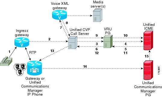
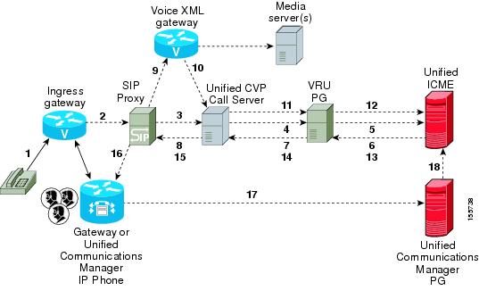
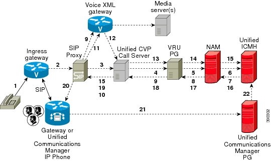
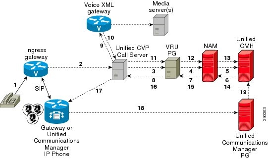
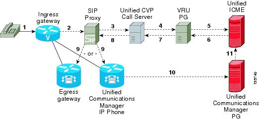
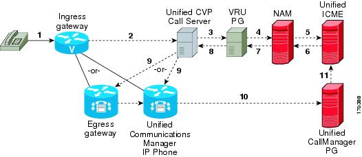
The following figures show the call flow for Comprehensive call flow model for ICME using SIP without and with a Proxy Server. The solid lines in these figures indicate voice paths and dashed lines indicate signaling paths.

Figure 3. Comprehensive Call Flow Model for ICME Using SIP Without a Proxy Server


Figure 4. Comprehensive Call Flow Model for ICME Using SIP With a Proxy Server


Note


Comprehensive Call Flow Model for ICMH

In the Comprehensive call flow model for ICMH, Unified CVP is deployed at the NAM where it acts as the switch, transferring the call to the Network VRU and to agents. The Network VRU uses the Correlation ID transfer mechanism. On the Operations Console, the IVR Service is configured to work with the VoiceXML Gateway to provide VRU treatment, and can include the ASR/TTS Servers.

In this call flow model:
  • There are two the Network VRUs: one on the NAM for the Switch leg and the VRU leg (Type 10) and the other for the CICM for the INCRP connection.

  • The Network VRU names (where applicable) and the ECC variable configurations must be identical on the NAM and CICM. All labels must also be duplicated but their routing clients will be different.

  • Use the SendToVRU node of the ICM Script Editor to connect the call to the Network VRU.


Note


  • This call flow model does not support calls that originate in IP address.

  • For instructions on how to implement IP-originated calls in a way which is supplemental to the Unified CVP Comprehensive Call Flow Model for ICME and ICMH, see the Calls Originated by Unified CM section. This implementation requires an additional Unified CVP Call Server to be connected to the CICM.


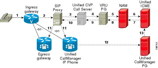
The following figures show the call flow for Comprehensive call flow model for ICMH using SIP without and with a Proxy Server. The solid lines in these figures indicate voice paths and dashed lines indicate signaling paths. The numbers in the figure indicate call flow progression.

Figure 5. Comprehensive Call Flow Model for ICMH Using SIP Without a Proxy Server
Figure 6. Comprehensive Call Flow Model for ICMH Using SIP With a Proxy Server

Note


  • The figures show two Gateways: the one where a call arrives and the other for the VRU leg. However, one physical Gateway can be used for both the purposes. Similarly, the IVR Service configured through the Operations Console and the peripheral gateway can be on the same server.

  • For simplicity, the figures do not illustrate redundancy and failover.

  • For more information, see REFER Transfers and Set Up sendtooriginator Setting in the SIP Service of a Call Server.


Table 3. Required and Optional CVP Components for Comprehensive Call Flow Model

CVP components

Related topics

Required CVP components

Operations Console

Operations Console

Ingress Gateway

  • Gateway Configuration

  • Configure Gateway Settings for Comprehensive Call Flow Model

  • Call Survivability

VoiceXML Gateway

  • Gateway Configuration

  • Configure Gateway Settings for Comprehensive Call Flow Model

  • Call Survivability

Unified ICME

  • Unified ICM Configuration

  • Comprehensive Call Flow Model for ICME

  • Comprehensive Call Flows for Pre-Routed Calls

  • Calls Arriving at ICME through a Pre-Route-Only NIC

  • Calls Originated by Unified CM

  • Calls Originated by an ACD or Call Routing Interface

  • Configure ICM Settings for Comprehensive Call Flow Model for ICME and ICMH

  • Define Unified CVP ECC Variables

Unified ICMH

  • Unified ICM Configuration

  • Comprehensive Call Flow Model for ICMH

  • Configure ICM Settings for Comprehensive Call Flow Model for ICME and ICMH

  • Configure Common Unified ICMH for Unified CVP Switch Leg

  • Define Unified CVP ECC Variables

Call Server

  • Call Server Configuration

  • REFER Transfers

Optional CVP components

Speech Servers

Speech Server Configuration

SIP Proxy Server

SIP Proxy Server Configuration

Media Servers

Media Server Configuration

DNS Servers

DNS Zone File Configuration for Comprehensive Call Flow Model

Reporting Server

Reporting Server Configuration

Set Up Comprehensive Call Flow Model Using SIP for ICME and ICMH

Procedure


Step 1

Perform Steps 1 to 5 of the Configure Gateway Settings for Comprehensive Call Flow Model procedure.

Step 2

(Optional) Configure a dial-peer for ringtone and error.

Step 3

If you are using a Proxy Server, configure your session target in the outbound Dial-peer to point to the Proxy Server.

Step 4

If you are using the sip-server global configuration, configure the sip-server in the sip-ua section to be your Proxy Server and point the session target of the dial-peer to the sip-server global variable.

Note

 
  1. Make sure your Dial plan includes this information. See the Dial plan when you configure the SIP Proxy Server for Unified CVP.

  2. The SIP Service voip dial-peer and the destination pattern on the Ingress Gateway must match the DNIS in static routes on the SIP Proxy Server or Unified CVP Call Server.

See the SIP Devices Configuration and SIP Dialed Number Pattern Matching Algorithm for detailed information.

Step 5

Perform Steps 6 to 10 of the Configure Gateway Settings for Comprehensive Call Flow Model procedure.

Step 6

Configure the ICM VRU Label. See Example of Dial-peer for ICM VRU Label for Type 8 Call Flow Model of the Configure ICM Settings for VRU-Only Call Flow Model: Type 8 section.

Step 7

(Optional) Enable security for media fetches.

Note

 
  • The VXML that the IVR Service returns as a response to an HTTP/HTTPS request from the VXML gateway contains URLs to media servers, so that the gateway knows where to fetch the media files from.

  • To enable HTTPS communication between CVP and VVB or IOS, use the ICM Script Set Variables to specify the protocol/port in the call.user.microapp_server. An example of a URL that explicitly specifies an HTTP scheme is http://<servername>:80. One that specifies an HTTPS scheme is https://<servername>:443. An example of a URL that does not specify the scheme is <servername>.

    In the Operations Console, the user-visible text for this property is "Use Security for Media Fetches." Do not restart the Call Server for this property to take effect.

Click the Use Security for Media Fetches check box on the IVR Service tab.

See the Operations Console online help for detailed information about the IVR Service.

Step 8

Perform Steps 11 to 13 of the Configure Gateway Settings for Comprehensive Call Flow Model procedure.

Step 9

Configure the speech servers to work with Unified CVP.

Caution


The Operations Console can only manage speech servers installed on Windows, not on Linux. If the speech server is installed on Linux, the server cannot be managed.

To ensure that the speech servers work with Unified CVP, make the following changes on each speech server as part of configuring the Unified CVP solution.

Step 10

Configure the characteristics for the VRU leg.

Characteristics for VRU legs require ASR and TTS treatment. On IOS VXML Gateway, if you have other requirements for DTMF relay, codecs or VAD settings, you must modify the commands accordingly.

Step 11

Perform Steps 14 and 15 of the Configure Gateway Settings for Comprehensive Call Flow Model procedure.

Step 12

Define Network VRUs.

  1. On Unified ICME or the NAM, ICM Configuration Manager, select Network VRU Explorer tool, define a Network VRU for the VRU leg and labels for each Unified CVP Call Server.

  2. On the CICM only, ICM Configuration Manager, select Network VRU Explorer tool, define a Network VRU for the VRU leg and labels for reaching the NAM.

For each of the two previous substeps, specify the following:

  • Type: 10

  • Name: <Network VRU Name>

    For example: cvp

  • Define a label for each Unified CVP Call Server that is handling the Switch leg:

    • Label: <Network Routing Number>

    • Type: Normal

    • Routing client for Unified ICME or the NAM: Select the routing client configured for that Unified CVP Call Server peripheral from the drop-down list.

    • Routing client for CICM only : Select the INCRP routing client from the drop-down list.

Note


The Network VRU label in the NAM and CICM must be identical. The Network VRU Names on the NAM and CICM should also be identical to avoid confusion.

Step 13

Define network VRUs and PGs for the switch leg in the ICM Configuration Manager.

On Unified ICMH, on the NAM and CICMs, Network VRU Explorer tool, define one label per Unified CVP Call Server or NIC routing client.

Note


Use the same Type 10 Network VRU that you defined in the previous steps for the VRU leg.

For more information, see the ICM Configuration Guide for Cisco ICM Enterprise Edition.

Step 14

Set the client type for the INCRP NIC.

On the CICM, ICM Configuration Manager, NIC Explorer tool, set the client type for the INCRP NIC.

  • Client Type: VRU

Step 15

Define a VRU that uses INCRP.

On the CICM, ICM Configuration Manager, Network VRU Explorer tool:

  1. Define a Network VRU with a label that uses INCRP as its routing client.

    Specify the following:

    • Type: 10

    • Name: <name of Unified CVP VRU>

      For example: cvpVRU

  2. Define one label for the NAM routing client.

    Specify the following:

    • Type: Normal

    • Label: <Network Routing Number>

    • Routing client: INCRP NIC

For more information, see the ICM Configuration Guide for Cisco ICM Enterprise Edition .

Step 16

Perform Step 16 of the Configure Gateway Settings for Comprehensive Call Flow Model procedure.

Step 17

Define a default network VRU on Unified ICME or the NAM, in the ICM Configuration Manager, the System Information tool:

  1. For Unified ICME or on the CICM only, define a default Network VRU.

    • Define the Default Network VRU: <Network VRU Name>

      For example: cvpVRU

  2. If there are Routing Scripts on the NAM, define a default Network VRU.

For more information, see the ICM Configuration Guide for Cisco ICM Enterprise Edition.

Step 18

Configure dialed numbers, call types, and customers on the Unified ICME or Unified ICMH Server in the ICM Configuration Manager:

  1. Dialed Number List Tool tab: Configure the dialed numbers.

  2. Call Type List tool tab: Configure the call types.

  3. ICM Instance Explorer tool tab: Configure the applicable customers.

For more information, see the ICM Configuration Guide for Cisco ICM Enterprise Edition.

Step 19

Configure ECC variables.

On Unified ICME, ICM Configuration Manager, configure ECC variables.

For more information, see Define Unified CVP ECC Variables.

Step 20

Create a routing script that handles the incoming calls.

On the Unified ICME or Unified ICMH Server in the ICM Script Editor tool, use the SendToVRU node to connect the call to the Network VRU.

See Scripting and Media Routing Guide for Cisco Unified ICM/Contact Center Enterprise & Hosted for more information.

Step 21

(Optional) Configure the SIP Proxy.

If using a SIP Proxy Server, configure it in the Unified CVP Operations Console.

Select: Device Management > SIP Proxy Server

Step 22

Install and configure the Call Server(s).

In the Operations Console:

  1. Enable the ICM, IVR, and SIP Services on the Call Server.

    • In the Operations Console select Device Management > Unified CVP Call Server.

    • Select theICM and SIP check boxes.

  2. Configure the IVR service.

    • In the Operations Console select Device Management > Unified CVP Call Server > IVR tab and configure the and configure the IVR service.

      Check the default values and change, if desired. Refer to the Operations Console online help for information about other settings you might want to adjust from their default values.

  3. In the Operations Console select Device Management > Unified CVP Call Server > SIP. Configure the SIP Service:

    • If you are using a SIP Proxy Server, enable the Outbound Proxy and select the SIP Proxy Server.

      Select the SIP tab and configure the following:

      • Enable Outbound Proxy: Yes

      • Outbound Proxy Host: Select from drop-down list.

      • Configure Local Static Routes on the SIP Proxy Server itself.

    • If you are not using a SIP Proxy Server, configure Local Static Routes using the Dialed Number Pattern system configuration on the Operations Console. A Local Static Route must be configured for each SIP gateway/ACD, SIP endpoint in order to receive calls.

      Local Static Routes, Dialed Number (DN): Specify the dialed number pattern for the destination.

      Valid number patterns include the following characters:

      • Use the period (.) or X character for single-digit wildcard matching in any position.

        Note


        Small letter "x" cannot be used as a wildcard.

      • Use the greater than (>), asterisk (*), or exclamation (!) characters as a wildcard for 0 or more digits at the end of the DN.

      • Do not use the T character for wildcard matching.

      • Dialed numbers must not be longer than 24 characters.

      • See Valid Format for Dialed Numbers for format and precedence information.

      Example: 9> (Errors are 9292 and ringtone is 9191)

      See SIP Dialed Number Pattern Matching Algorithm for more information.

      The following examples show the incorrect and correct static route configurations. The incorrect static route configuration does not show the least explicit routes at the end. Also, load balancing and failover of calls require DNS SRV domain names, not multiple routes with the same DN Pattern, but a single route to an SRV domain name.

      Example: Incorrect static route configuration
      1>,10.2.6.1
      2>,10.2.6.2
      3>,10.2.6.20
      2229191>,10.2.6.241
      2229292>,10.2.6.241
      2229191>,10.2.6.242
      2229292>,10.2.6.242
      2>,ccm-subscribers.cisco.com
      3>,ccm-subscribers.cisco.com
      
      Example: Correct static route configuration
      22291>,cvp-ringtone.cisco.com
      22292>,cvp-error.cisco.com
      1>,ccm-subscribers.cisco.com
      2>,ccm-subscribers.cisco.com
      3>,ccm-subscribers.cisco.com
      

      Note


      "91919191>" pattern does not match an exact DN of "91919191."

    • Check the default values for the SIP Service and change, if desired.

  4. Configure the ICM Service by setting the maximum length DNIS to the length of the Network Routing Number.

    Select Device Management > CVP Call Server > ICM tab: Maximum Length of DNIS: length of the Network Routing Number.

    Example: if the Gateway dial pattern is 1800******, the maximum DNIS length is 10.

Step 23

Configure Local Static Routes:

If an outbound proxy is enabled on the Operations Console, configure local static routes on the SIP Proxy Server.

If no outbound proxy is enabled, configure local static routes using the Operations Console Dialed Number Pattern system configuration. Refer to SIP Dialed Number Pattern Matching Algorithm for detailed information.

The following example shows a local static route configuration. A local static route contains a dialed number pattern and a routing address (IP Address, Hostname, or SIP Server Group name):

  • 22291>,cvp-ringtone.cisco.com

  • 22292>,cvp-error.cisco.com

  • 1>,ccm-subscribers.cisco.com

  • 2>,ccm-subscribers.cisco.com

  • 3>,ccm-subscribers.cisco.com

Step 24

Configure custom ringtone patterns. See Add and Deploy Dialed Number Pattern.

Step 25

(Optional) Configure the Reporting Server and associate it with a Call Server.

On the Operations Console, select Device Management > CVP Reporting Server > General and complete the following steps:

  1. Configure the Reporting Server.

  2. Select a Call Server to associate with this Reporting Server.

  3. Check the default values of the Reporting properties and change, if desired.

For more information, see the Reporting Guide for Cisco Unified Customer Voice Portal available at https://www.cisco.com/c/en/us/support/customer-collaboration/unified-customer-voice-portal/products-user-guide-list.html.


DNS Zone File Configuration for Comprehensive Call Flow Model

DNS Zone File Linux NAMED Configuration Example


         ringtone-1 IN A 10.86.129.20
         ringtone-2 IN A 10.86.129.229
         vxml-1 IN A 10.86.129.20
         vxml-2 IN A 10.86.129.229
         vxml-3 IN A 161.44.81.254
         cvp-1 IN A 10.86.129.211
         cvp-2 IN A 10.86.129.220
         cvp-3 IN A 161.44.81.254
         ; Priority Weight Port Target
         sip._tcp.ringtone.sox.cisco.com. SRV 1 1 5060 ringtone-1.sox.cisco.com.
         _
         SRV 1 1 5060 ringtone-2.sox.cisco.com.
         sip._udp.ringtone.sox.cisco.com. SRV 1 1 5060 ringtone-1.sox.cisco.com.
         _
         SRV 1 1 5060 ringtone-2.sox.cisco.com.
         _sip._tcp.vxml.sox.cisco.com. SRV 1 1 5060 vxml-1.sox.cisco.com.
         SRV 1 1 5060 vxml-2.sox.cisco.com.
         SRV 1 1 5060 vxml-3.sox.cisco.com.
         _sip._udp.vxml.sox.cisco.com. SRV 2 1 5060 vxml-1.sox.cisco.com.
         SRV 2 1 5060 vxml-2.sox.cisco.com.
         SRV 1 1 5060 vxml-3.sox.cisco.com.
         _sip._tcp.cvp.sox.cisco.com. SRV 1 1 5060 cvp-1.sox.cisco.com.
         SRV 2 1 5060 cvp-2.sox.cisco.com.
         SRV 3 1 5060 cvp-3.sox.cisco.com.
         _sip._udp.cvp.sox.cisco.com. SRV 1 1 5060 cvp-1.sox.cisco.com.
         SRV 2 1 5060 cvp-2.sox.cisco.com.
         SRV 3 1 5060 cvp-3.sox.cisco.com.
                            

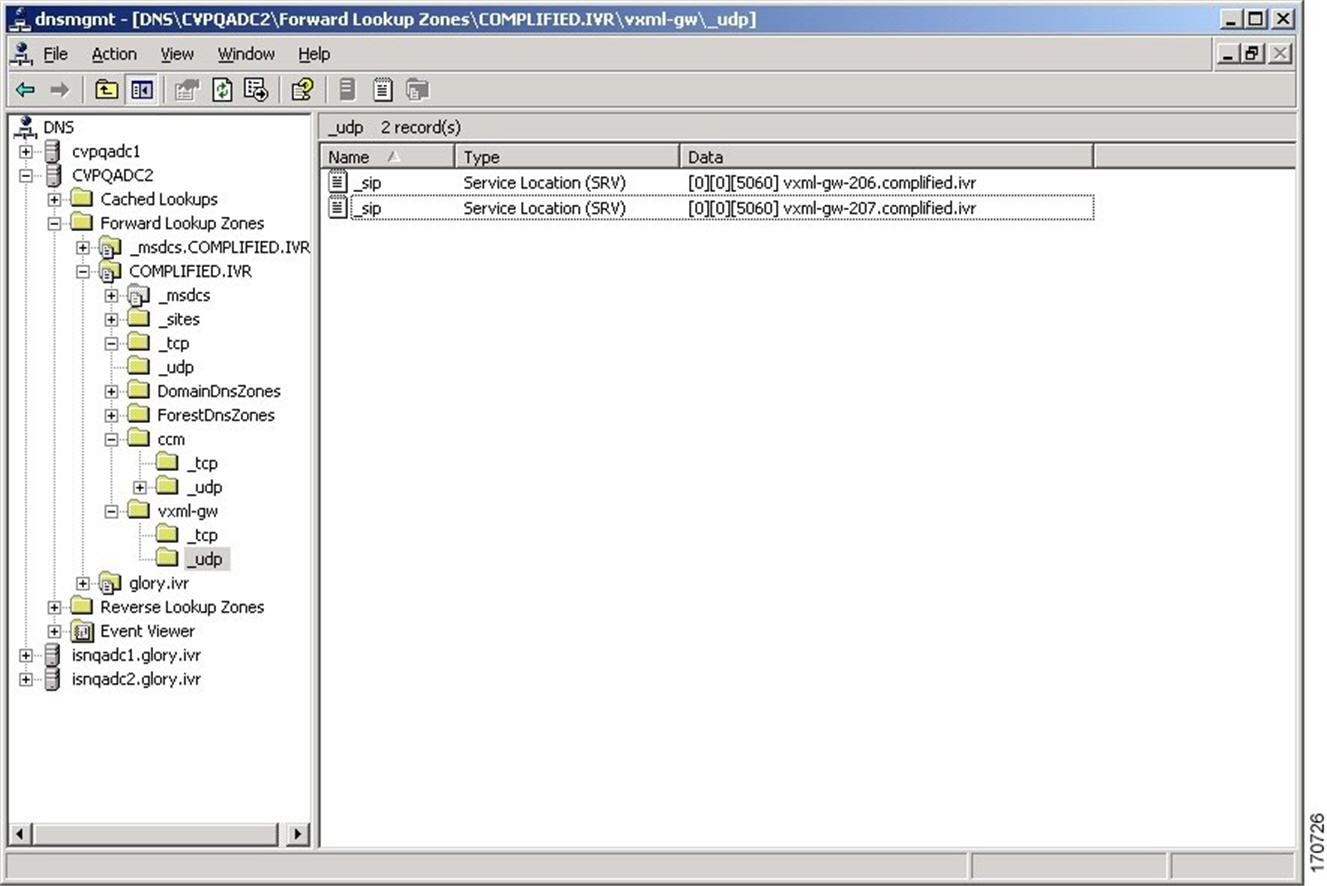
DNS Zone File MS DNS Configuration Example


Characteristics for the VRU Leg for Comprehensive Call Flow Model in IOS Gateway

Use the following commands to provide voice treatment:


Note


This applies only to IOS VXML Gateway.

new-call is a required name.

Continue with the VRU Leg Example.


service vru-leg flash:bootstrap.tcl
 !
service new-call flash:bootstrap.vxml
 !
service handoff flash:handoff.tcl
 !
service ringtone flash:ringtone.tcl
 !
service cvperror flash:cvperror.tcl
 !
service cvp-survivability flash:survivability.tcl
 !

REFER Transfers

Unified CVP SIP Service can perform a SIP REFER transfer instead of using SIP re-invites, which allows Unified CVP to remove itself from the call, thus freeing up licensed Unified CVP ports.

Unified CVP cannot run further call control operations after this kind of label has been run. For example, it cannot perform subsequent transfers back to Unified CVP for self service or queuing to another agent.

However, if the transfer fails, configure survivability to transfer the call elsewhere. This process is not the same as an ICM router requery; for example, it will appear as a new call to Unified ICME, but it is a way to take an alternate action, if the transfer fails.


Note


  • This feature can be used in Comprehensive (SIP only), Call Director, and Standalone call flow models.

  • Router requery can be performed with a REFER transfer only if the NOTIFY messages are sent back to Unified CVP with the result of the REFER operation. Unified CVP does not end the call after sending REFER and hence, it is possible to requery Unified ICM, get another label, and send another REFER.

  • The use of the survivability tcl service on the ingress gateway cannot currently support sending the NOTIFY messages with a failed transfer result, so router requery cannot be used with REFER when it is handled by the survivability service. Survivability service can handle REFER, except that it will always report a successful transfer to Unified CVP, even when the transfer failed. This is a known limitation of the TCL IVR API for REFER handling in IOS, including ingress and CUBE gateways.


Using this feature, the call can be queued at the VoiceXML gateway and then sent to an agent with a Unified ICME label that begins with the letters "rf." Otherwise, standard Unified ICME agent labels enable Unified CVP to remain in the signaling path for the duration of the call, and the licensed Unified CVP resource will not be freed until the end of the call. REFER transfers can be made to Unified CM or other SIP endpoints in the SIP cloud, such as an ACD. The ECC variable "user.sip.refertransfer" can also be set in Unified ICME scripts. (When using this ECC variable in a Unified ICME script, it must be set to the value of the single character "y" and Unified CVP will use REFERs when transferring to the agents.

When using REFER transfers, including the REFER used to play back critical_error.wav for abnormal disconnects, the Ingress gateway must include an outbound voip dial peer. This outbound dial peer is necessary because when the REFER message enters the gateway from the Call Server, it needs to match an outbound dial peer in order for the call to succeed; otherwise, a 503 rejection occurs if no dial peers match the REFER-TO header URI. Dial peer destination targets must match the labels in the REFER-TO SIP URI; meaning that <errorDN>@<sip-server> and other labels that may be used in the Unified ICME routing label. For example:


          dial-peer voice 1050 
          voip destination-pattern 1... 
          voice-class codec 1 
          session protocol sipv2 
          session target <your sip-server destination> 
          dtmf-relay rtp-nte 
          no vad
 

When configuring Route Patterns on Unified CM for REFERs to destinations outside of the cluster, such as to the CUSP Server or the gateways directly, you must add SIP Route Pattern for the SIP Trunk associated with that endpoint. For example, if you use REFER to Error DN to the IP Originated caller on Unified CM, and the host of the REFER To header SIP URL is the CUSP Server, you must create a SIP Route Pattern with that IP address or domain name and associate it with your SIP Trunk for the CUSP Server.


Note


  • When a TDM gateway handles REFER, and not Cisco Unified Border Element (CUBE), a REFER triggered INVITE is sent out. The REFER triggered INVITE requires a dial peer with a session target and typical codec information. The REFER-TO header URI host that is formulated by the CVP routing algorithm configuration, is ignored.

  • When CUBE receives a CVP initiated REFER, it does not send it transparently through to the originator. A dial peer is required to match the DN (user portion of the REFER-TO header URI) and the host portion of the URI is rewritten to match the session target of the dial peer. The REFER is passed to the originator using cli "supplementary-service sip refer"; otherwise, CUBE will handle the REFER and send the triggered invite to the refer DN on its own as a back to back user agent.


Comprehensive Call Flows for Pre-Routed Calls

This class of call flows is similar to the Unified CVP Comprehensive call flow models, except that the calls are first introduced into Unified ICME or Unified ICMH using a path other than through Unified CVP. A Unified ICME routing script is run to pre-route such calls before Unified CVP even sees them. After the script transfers the call to Unified CVP, for either self-service or queuing, a standard Unified CVP Comprehensive call flow model is used.

All the above call flows are similar because the original routing client is capable of a single route request only. A routing client is an NIC, a Unified CM, an ACD, or a VRU. A routing client makes a single request to Unified ICME, then the Unified ICME returns a destination label, and the routing client affects the transfer. At that point the route request dialog is ended, and Unified ICME neither sends a subsequent label nor conducts any form of third-party call control.

If the returned label was a translation route to VRU label, or if it was a correlation ID label resulting from a SendToVRU node, the routing script may run. In such a case, the call is transferred to Unified CVP, and the routing script continues to run after Unified CVP receives the call. The script then invokes micro-application requests as part of its queuing or self service treatment. If the call is then transferred to an agent or skill group, that label goes to Unified CVP rather than to the original routing client. If the call is to be blind-transferred later to another agent or skill group, or back into Unified CVP for additional queuing or self service, that label too goes to Unified CVP rather than to the original routing client.

When the call arrives at Unified CVP, for micro-applications to be supported, it must establish both the Switch and the VRU leg. In other words, it must enter a general Unified CVP Comprehensive call flow model. The only difference between the pre-routed call and Comprehensive call flow model is the way a call first arrives at Unified CVP. If a call is pre-routed, it arrives using either a translation route or correlation-id transfer, whereas in the Comprehensive call flow model, the call arrives as a new call from the public switched telephone network (PSTN). In both the cases, a subsequent transfer to VRU leg of Unified CVP is required.

This section focuses on the following call flows:

Calls Arriving at ICME Through a Pre-Route-Only NIC

The following Unified ICME NICs fall into this category: ATT, GKTMP, MCI, Sprint, Stentor. This call flow applies to both the Comprehensive call flow models for ICME and ICMH. In the latter, both Unified CVP and the NIC are deployed at NAM.

Based on the Release number of ICME, perform the following tasks:

Table 4. Procedure for Different Releases of ICME

ICME Release

Procedure

ICME Release 7.1 onwards

  1. Configure a single Type 10 Network VRU and associate it with all Unified CVP peripherals in the PG Explorer configuration tool, and in the System Information tool, define it as the default system Network VRU.

  2. To support the initial call transfer to Unified CVP from the preroute routing client, configure Translation Route labels to target the Unified CVP peripherals.

  3. To support the transfer to VRU leg, configure the Type 10 Network VRU that you defined in Step 1 with Network Routing Number labels for each Unified CVP peripheral routing client.

  4. Associate all micro-application VRU scripts with that same Type 10 Network VRU. When the routing script transfers the call to Unified CVP, it must use a TranslationRouteToVRU node. The transfer to VRU leg of Unified CVP happens automatically.

    Note


    Non-prerouted calls can also share the same Network VRU and Call Servers.

ICME Release 7.0 onwards

  1. Configure Type 7 and Type 10 Network VRUs.

  2. In the PG Explorer tool, assign all Unified CVP Call Servers to the Type 7 Network VRU.

  3. Configure one set of Translation Route labels to target the Type 7 Call Servers. These sets are used to transfer the call from the original routing client to the Unified CVP Switch leg.

  4. Assign a label to the Type 10 Network VRU for each Unified CVP Call Server routing client, whose label string is set to the Network Routing Number.

  5. In the System Information configuration tool, configure the Type 10 Network VRU as the system default Network VRU.

  6. Associate all micro-application VRU scripts with the Type 10 Network VRU.

    Note

     
    • When the routing script transfers the call into Unified CVP, it must use two nodes in succession: first, a TranslationRouteToVRU, and then an explicit SendToVRU node. The first node transfers the call from the initial routing client to one of the Type 7 Call Servers (Unified CVP Switch leg); the second one transfers the call from the Type 7 Call Server to the Unified CVP VRU leg. (The VRU leg will usually end up running through the same Unified CVP Call Server as the Switch leg.)

    • Non-prerouted calls can also share the same Type 7 Call Servers and Type 7 and Type 10 Network VRUs; however, scripts which handle non-prerouted calls must also use an explicit SendToVRU node before they can run any micro-applications.

Calls Originated by Unified CM

This category includes the following types of calls:

  • Internal Help Desk calls: For these calls, the Unified Communication Manager (CM) phone user calls a CTI Route Point, which starts a routing script that can optionally deliver the call to Unified CVP for queuing or self-service.

  • Unified ICME Outbound Option calls: For these calls, a dialer makes outbound calls and then transfers them to a CTI Route Point, which starts a routing script that can optionally deliver the call to Unified CVP for queuing or self-service.

  • Consultative Warm Transfer: For these calls, a Unified CM agent places the caller on hold and dials in to Unified ICME to reach a second agent; this starts a routing script that can optionally deliver the call to Unified CVP for queuing or self-service.


Note


For information about Consultative Warm Transfer, see Configure Unified ICME Warm Consult Transfer/Conference to Unified CVP.

Note


If these call flows are used in a Cisco Unified Contact Center Management Portal environment, the target Unified CVP Call Servers are required to be connected to the same CICM as the Unified CM from which the call originates. For example, multiple CICMs will require multiple Unified CMs, so will they require multiple Unified CVP Call Servers.

Further configuration points differ depending on whether Unified CVP is being deployed with Unified ICME Release 7.0 or 7.1 and later.

ICME Release Task

Unified ICME Release 7.0 onwards

  1. Configure a single Type 10 Network VRU and defined as the default system Network VRU in the System Information tool.

  2. Configure the Type 10 Network VRU with two sets of labels. Associate the first set with the Unified CM routing client, which contains a label that Unified CM uses to transfer the call to Unified CVP. Configure Unified CM with a series of route patterns, which include that label followed by one to five arbitrary digits. For example, if the selected label is 1111, then the following route pattern is needed: 1111!. The second set of Network VRU labels must contain the usual Comprehensive Model "Network Routing Number," which must be associated with each Unified CVP Call Server routing client.

    • When the routing script transfers the call into Unified CVP, it should use a single SendToVRU node. No subsequent node is necessary in order to perform the transfer to Unified CVP's VRU leg; this will take place automatically. (The SendToVRU node can be omitted since any micro-application script node will invoke the same functionality automatically; however, you can include this node explicitly in the script for troubleshooting purposes).

    • Non-prerouted calls can also share the same Network VRU and the same Unified CVP Call Servers as those calls which are transferred from Unified CM. However, the scripts which handle non-prerouted calls must also use an explicit SendToVRU node before they can run any micro-applications.

    Associate all micro-application VRU scripts with that same Type 10 Network VRU.

    Note

     
    • When the routing script transfers the call into Unified CVP, it should use a single SendToVRU node. No subsequent node is necessary in order to perform the transfer to Unified CVP's VRU leg; this will take place automatically. (The SendToVRU node can be omitted since any micro-application script node will invoke the same functionality automatically; however, you can include this node explicitly in the script for troubleshooting purposes.)

    • Non-prerouted calls can also share the same Network VRU and the same Unified CVP Call Servers as those calls which are transferred from Unified CM. However, the scripts which handle non-prerouted calls must also use an explicit SendToVRU node before they can run any micro-applications.

Unified ICME Release 7.1 onwards

  1. Configure two Network VRUs: one Type 7 and one Type 10.

  2. In the PG Explorer tool, assign the Unified CVP Call Servers to the Type 7 Network VRU.

  3. Configure one set of Translation Route labels to target the Type 7 Call Servers; these will be used to transfer the call from the original routing client to the Unified CVP Switch leg.

  4. Assign a label to the Type 10 Network VRU for each Unified CVP Call Server routing client, whose label string is set to the Network Routing Number.

  5. Configure the Type 10 Network VRU as the system default Network VRU in the System Information configuration tool.

  6. Associate all micro-application VRU scripts with the Type 10 Network VRU.

    Note

     
    • When the routing script to transfers the call into Unified CVP, it should use two nodes in succession: first, a TranslationRouteToVRU, and then an explicit SendToVRU node (which contrary to the Unified ICME 7.1 case, is not optional). The first node transfers the call from the initial routing client to one of the Type 7 Call Servers (Unified CVP Switch leg); the second one transfers the call from the Type 7 Call Server to the Unified CVP VRU leg. (The VRU leg will usually end up running through the same Unified CVP Call Server as the Switch leg.)

    • Non-prerouted calls can also share the same Type 7 Call Servers and Type 7 and Type 10 Network VRUs.

Calls Originated by an ACD or Call Routing Interface

These calls are very similar to those which arrive from a preroute-only NIC, except that the routing client is connected to Unified ICME using a PG rather than using a NIC. Therefore, if this call flow is used in a Unified ICMH environment, the target Unified CVP Call Servers are required to be connected to the same CICM as the ACD or CRI-based VRU from which the call originates. Just as multiple CICMs will require multiple ACD or VRU peripherals, so will they require multiple Unified CVP Call Servers.

Further configuration points differ depending on whether Unified CVP is being deployed with Unified ICME Release 7.0 or 7.1 and later

Table 5. Procedure for Different Releases of ICME
ICME Release Tasks
ICME Release 7.1 onwards
  1. Configure a single Type 10 Network VRU and associate it with all Unified CVP peripherals in the PG Explorer configuration tool, and also define it as the default system Network VRU in the System Information tool.

  2. In order to support the initial call transfer to Unified CVP from the pre-route routing client, configure Translation Route labels to target the Unified CVP peripherals.

  3. In order to support the transfer to VRU leg, configure the Type 10 Network VRU with Network Routing Number labels for each Unified CVP peripheral routing client.

  4. Associate all micro-application VRU scripts with that same Type 10 Network VRU.

    Note

     
    • When the routing script transfers the call into Unified CVP, it must use a TranslationRouteToVRU node. No subsequent node is necessary in order to perform the transfer to Unified CVP's VRU leg; this will take place automatically.

    • Non-prerouted calls can also share the same Network VRU and the same Unified CVP Call Servers.

ICME Release 7.0 onwards
  1. Configure two Network VRUs: one Type 7 and one Type 10.

  2. In the PG Explorer tool, assign all Unified CVP Call Servers to the Type 7 Network VRU.

  3. Configure one set of Translation Route labels to target the Type 7 Call Servers; these will be used to transfer the call from the original routing client to the Unified CVP Switch leg.

  4. Assign a label to the Type 10 Network VRU for each Unified CVP Call Server routing client, whose label string is set to the Network Routing Number.

  5. Configure the Type 10 Network VRU as the system default Network VRU in the System Information configuration tool.

  6. Associate all micro-application VRU scripts with the Type 7 Network VRU.

    Note

     
    • When the routing script transfers the call into Unified CVP, it should use two nodes in succession: first, a TranslationRouteToVRU, and then an explicit SendToVRU node. The first node transfers the call from the initial routing client to one of the Type 7 Call Servers (Unified CVP Switch leg); the second one transfers the call from the Type 7 Call Server to the Unified CVP VRU leg. (The VRU leg will usually end up running through the same Unified CVP Call Server as the Switch leg.)

    • Non-prerouted calls can also share the same Type 7 Call Servers and Type 7 and Type 10 Network VRUs.

Call Director Call Flow Model

In Call Director call flow model, Unified CVP provides ICME with VoIP call routing capabilities only. If you are using an ICM Server to queue calls or queue calls directly on an ACD, use your own Service Control VRU. Calls can be transferred multiple times, from Ingress, to customer-provided VRU, to either UCCE or customer-provided ACD or agent, and back again. When calls are connected to customer-provided equipment, their voice paths must go to an Egress gateway, which is connected by TDM to that equipment. If the signaling is SIP, then Unified CVP works with customer-provided SIP endpoints that have been tested and certified to interoperate with Unified CVP. No VXML Server or VXML Gateway is used in this model.

The following table lists the required and optional CVP components needed for the Call Director call flow model:

Table 6. Required and Optional CVP Components for Call Director Call Flow Model

CVP components

Related topics

Required CVP components

Call Server

Unified ICME

Ingress Gateway

Operations Console

Operations Console

Optional CVP components

Reporting Server

Reporting Server Configuration

SIP Proxy Server, if Call Server is configured to use SIP signaling

SIP Proxy Server Configuration

This section describes the following Call Director call flow models:

Call Director Call Flow Model for Unified ICME

In this call flow model, Unified CVP provides Unified ICME with VoIP call switching capabilities. Provide your own Service Control VRU, if you are using Unified ICME to queue calls or you might queue calls directly on your ACD. Calls might be transferred multiple times, from Ingress, to customer-provided VRU, to either Unified CCE or customer-provided ACD or agent, and back again. When calls are connected to customer-provided equipment (either VoIP or TDM), their voice paths must go to an egress gateway, which is connected by TDM to that equipment. If the signaling is SIP, then this call flow model works with customer-provided SIP endpoints which have been tested and certified to interoperate with Unified CVP.

The following figures show the call flow for Call Director call flow model for ICME using SIP without and with a Proxy Server. The solid lines in these figures indicate voice paths and dashed lines indicate signaling paths.

Figure 7. Call Director Call Flow Model for ICME Using SIP Without a Proxy Server


Figure 8. Call Director Call Flow Model for ICME Using SIP With a Proxy Server


Note


Call Director Call Flow Model for Unified ICMH

In this call flow model, Unified CVP only provides the Network Applications Manager (NAM) with VoIP call switching capabilities. If you are using the NAM to queue calls, or you might queue calls directly on your ACD, provide your own Service Control VRU. Calls may be transferred multiple times, from Ingress, to customer-provided VRU, to either the NAM or customer-provided ACD or agent, and back again. When calls are connected to customer-provided equipment, their voice paths must go to an egress gateway, which is connected by TDM to that equipment. If the signaling is SIP, then this call flow model works with customer-provided SIP endpoints which have been tested and certified to interoperate with Unified CVP.

The following figures show the call flow for Call Director call flow model for ICMH using SIP without and with a Proxy Server. The solid lines in these figures indicate voice paths and dashed lines indicate signaling paths.

Figure 9. Call Director Call Flow Model for ICMH Using SIP Without a Proxy Server


Figure 10. Call Director Call Flow Model for ICMH Using SIP With a Proxy Server


Note


Set Up Call Director Call Flow Model

Procedure


Step 1

Perform Steps 1 to 5 of the Configure Gateway Settings for Comprehensive Call Flow Model procedure.

Step 2

Configure the Ingress Gateway:

  1. Configure the Ingress Gateway dial-peer for the Unified CVP Call Server.

  2. Configure a dial-peer for ringtone and error.

  3. If you are using a Proxy Server, configure your session target in the outbound dial peer to point to the Proxy Server.

  4. If you are using the sip-server global configuration, then configure the sip-server in the sip-ua section to be your Proxy Server and point the session target of the dial-peer to the sip-server global variable.

Note


Make sure your dial plan includes this information. You will need to see the Dial plan when you configure the SIP Proxy Server for Unified CVP.

The SIP Service voip dial peer and the destination pattern on the Ingress Gateway must match the DNIS in static routes on the SIP Proxy Server or Unified CVP Call Server.

See the SIP Devices Configuration and SIP Dialed Number Pattern Matching Algorithm for detailed information.

Step 3

For SIP without a Proxy Server, complete the following steps:

  1. If you are using DNS query with SRV or A types from the gateway, configure the gateway to use DNS.

    See the Operations Console online help for details. If you are using DNS query with SRV or A types from the gateway, use the gateway configuration CLI as shown below:

    Non-DNS Setup:

    
    sip-ua
    sip-server ipv4:xx.xx.xxx.xxx:5060
    !
    

    DNS Setup:

    
    ip domain name patz.cisco.com
    ip name-server 10.10.111.16
    !
    sip-ua
    sip-server dns:cvp.pats.cisco.com
    !
    
  2. Configure the DNS zone file for the separate DNS server that displays how the Service (SRV) records are configured.

    Note


    SRV with DNS can be used in any of the SIP call flow models, with or without a Proxy server. Standard A type DNS queries can be used as well for the calls, without SRV, but they lose the load balancing and failover capabilities.

    See the DNS Zone File Configuration for Call Director Call Flow Model for more information.

Step 4

For SIP with a Proxy Server, use one of the following methods:

Note


You can configure the Gateway statically instead of using DNS.

The following example shows how both the A and SRV type records could be configured:


ip host cvp4cc2.cisco.com 10.4.33.132
ip host cvp4cc3.cisco.com 10.4.33.133
ip host cvp4cc1.cisco.com 10.4.33.131

For SIP/TCP:


ip host _sip._tcp.cvp.cisco.com srv 50 50 5060 cvp4cc3.cisco.com
ip host _sip._tcp.cvp.cisco.com srv 50 50 5060 cvp4cc2.cisco.com
ip host _sip._tcp.cvp.cisco.com srv 50 50 5060 cvp4cc1.cisco.com

For SIP/UDP:


ip host _sip._udp.cvp.cisco.com srv 50 50 5060 cvp4cc3.cisco.com
ip host _sip._udp.cvp.cisco.com srv 50 50 5060 cvp4cc2.cisco.com
ip host _sip._udp.cvp.cisco.com srv 50 50 5060 cvp4cc1.cisco.com

Note


The DNS Server must be configured with all necessary A type or SRV type records.

See the SIP Devices Configuration.

If you are using the DNS Server, you can set your SIP Service as the Host Name (either A or SRV type).

Step 5

On the Unified CM server, CCMAdmin Publisher, complete the following SIP-specific actions:

  1. Create SIP trunks.

    • If you are using a SIP Proxy Server, set up a SIP trunk to the SIP Proxy Server.

    • Add a SIP Trunk for the Unified CVP Call Server.

    • Add a SIP Trunk for each Ingress gateway that will send SIP calls to Unified CVP that might be routed to Unified CM.

    To add an SIP trunk, select Device > Trunk > Add New and use the following parameters:

    • Trunk Type: SIP trunk

    • Device Protocol: SIP

    • Destination Address: IP address or host name of the SIP Proxy Server (if using a SIP Proxy Server). If not using a SIP Proxy Server, enter the IP address or host name of the Unified CVP Call Server.

    • DTMF Signaling Method: RFC 2833

    • Do not check the Media Termination Point Required check box.

    • If you are using UDP as the outgoing transport on Unified CVP, also set the outgoing transport to UDP on the SIP Trunk Security Profile.

    • Connection to CUSP Server: use 5060 as the default port.

  2. Add route patterns for outbound calls from the Unified CM devices using a SIP Trunk to the Unified CVP Call Server. Also, add a route pattern for error DN.

    Select Call Routing > Route/Hunt > Route Pattern > Add New

    Add the following:

    • Route Pattern: Specify the route pattern; for example: 3XXX for a TDM phone that dials 9+3xxx and all Unified ICME scripts are set up for 3xxx dialed numbers.

    • Gateway/Route List: Select the SIP Trunk defined in the previous substep.

    Note


    For warm transfers, the call from Agent 1 to Agent 2 does not typically use a SIP Trunk, but you must configure the CTI Route Point for that dialed number on the Unified CM server and associate that number with your peripheral gateway user (PGUSER) for the JTAPI gateway on the Unified CM peripheral gateway. An alternative is to use the Dialed Number Plan on Unified ICME to bypass the CTI Route Point.

  3. If you are sending calls to Unified CM using an SRV cluster domain name, select Enterprise Parameters > Clusterwide Domain Configuration and add the Cluster fully qualified domain name FQDN.

Step 6

(Optionally) Configure the SIP Proxy Server.

  1. Configure the SIP static routes to the Unified CVP Call Servers, Unified CM SIP trunks, and Gateways.

    Configure the SIP static routes for intermediary transfers for ringtone, playback dialed numbers, and error playback dialed numbers.

    Note


    For failover and load balancing of calls to multiple destinations, configure the CUSP server static route with priority and weight.

  2. Configure Access Control Lists for Unified CVP calls.

    Select Proxy Settings > Incoming ACL.

    Address pattern: all

  3. Configure the service parameters.

    Select Service Parameters, then set the following:

    • Add record route: off

    • Maximum invite retransmission count: 2

    • Proxy Domain and Cluster Name: if using DNS SRV, set to the FQDN of your Proxy Server SRV name

  4. Write down the IP address and host name of the SIP Proxy Server. (You need this information when configuring the SIP Proxy Server in Unified CVP.)

  5. If using redundant SIP Proxy Servers (primary and secondary or load balancing), then decide whether to use DNS server lookups for SRV records or non-DNS based local SRV record configuration.

    Note


    If a single CUSP Server is used, then SRV record usage is not required.

    Configure the SRV records on the DNS server or locally on Unified CVP with a .xml file (local xml configuration avoids the overhead of DNS lookups with each call).

    Note


    See the Local SRV File Configuration Example for SIP Messaging Redundancy section for details.

    The Call Director call flow model with SIP calls will typically be deployed with dual CUSP servers for redundancy. In some cases, you might want to purchase a second CUSP server. Regardless, the default transport for deployment will be UDP; make sure you always disable the record-route in a CUSP server as this advanced feature is not supported in Contact Center deployments.

    For the required settings in the Unified CM Publisher configuration, see the Cisco Unified SIP Proxy documentation.

Step 7

Configure the PGs for the switch leg.

On Unified ICME, ICM Configuration Manager, PG Explorer tool:

  1. Configure each peripheral gateway (PG) to be used for the Switch leg. In the tree view pane, select the applicable PG, and set the following:

    1. Logical Controller tab:

      • Client Type: VRU

      • Name: A name descriptive of this PG

        For example: <location>_A for side A of a particular location

    2. Peripheral tab:

      • Peripheral Name: A name descriptive of this Unified CVP peripheral

        For example: <location>_<cvp1> or <dns_name>

      • Client Type: VRU

      • Select the check box: Enable Post-routing

    3. Routing Client tab:

      • Name: By convention, use the same name as the peripheral.

      • Client Type: VRU

    For more information, see the ICM Configuration Guide for Cisco ICM Enterprise Edition.

  2. Configure a peripheral for each Unified CVP Call Server to be used for a Switch leg connected to each PG.

Step 8

Configure dialed numbers.

On the Unified ICME or Unified ICMH Server, in the ICM Configuration Manager, configure the following items:

  1. Dialed Number List Tool tab: Configure the dialed numbers.

  2. Call Type List tool tab: Configure the call types.

  3. ICM Instance Explorer tool tab: Configure the applicable customers.

For more information, see the ICM Configuration Guide for Cisco ICM Enterprise Edition.

Step 9

Create a Routing Script.

On the Unified ICME or Unified ICMH Server in the ICM Script Editor tool:

Create a routing script that handles the incoming call. The routing script must run a Label node or Select node (node that returns a label right away).

Note


Do not use the Queue node in the routing script.

The label must be configured in the SIP Proxy Server to the IP address of the device that the label corresponds to. The Proxy Server is optional. If you do not have one, you must configure the Gateway dial-peer to point to the Call Server (refer to the first step in this process). Also, you must configure the destination labels in the SIP Service for the Call Server.

See the Scripting and Media Routing Guide for Cisco Unified ICM/Contact Center Enterprise & Hosted for more information.

Step 10

Configure the SIP Proxy Server using the Operations Console.

Select Device Management > SIP Proxy Server.

Step 11

In the Operations Console, install and configure Call Servers.

  1. Enable the ICM and SIP Services on the Call Server.

    In the Operations Console, select Device Management > Unified CVP Call Server.

    Select the check boxes: ICM and SIP

  2. Configure the SIP Service:

    Select Device Management > CVP Call Server > SIP tab.

    • If you are using a SIP Proxy Server, enable the Outbound Proxy and select the SIP Proxy Server. If using a SIP Proxy Server, configure Local Static Routes on the SIP Proxy Server itself.

    • If you are not using a SIP Proxy Server, configure Local Static Routes using the Dialed Number Pattern system configuration in the Operations Console. A local static route must be configured for each SIP gateway/ACD, SIP endpoint in order to receive calls.

    • Check the default values for the SIP Service and change, if desired.

    See the SIP Dialed Number Pattern Matching Algorithm for detailed information.

  3. Configure the ICM Service by setting the maximum length DNIS to the length of the Network Routing Number:

    • Select Device Management > CVP Call Server > ICM tab.

    • Set the Maximum Length of DNIS to length of the Network Routing Number.

    Example: if the Gateway dial pattern is 1800******, the maximum DNIS length is 10.

    For detailed information, see the Operations Console online help.

Step 12

Configure local static routes:

If an outbound proxy is enabled on the Operations Console, configure local static routes on the SIP Proxy Server.

If no outbound proxy is enabled, configure local static routes using the Operations Console Dialed Number Pattern system configuration. See the SIP Dialed Number Pattern Matching Algorithm for detailed information.

The following is an example of a local static route configuration. A local static route contains a dialed number pattern and a routing address (IP Address, Hostname, or SIP Server Group name):

  • 22291>,cvp-ringtone.cisco.com

  • 22292>,cvp-error.cisco.com

  • 1>,ccm-subscribers.cisco.com

  • 2>,ccm-subscribers.cisco.com

  • 3>,ccm-subscribers.cisco.com

Step 13

(Optional) On the Operations Console, configure the Reporting Server. Select Device Management > CVP Reporting Server > General tab:

  1. Configure the Reporting Server.

  2. Select a Call Server to associate with this Reporting Server.

  3. Check the default values of the Reporting properties and change, if desired.

For more information, see the Reporting Guide for Cisco Unified Customer Voice Portal available at https://www.cisco.com/c/en/us/support/customer-collaboration/unified-customer-voice-portal/products-user-guide-list.html.


Examples: Ingress Gateway Configuration

Example: Gateway Settings for Call Director Call Flow Model
The first part of the following example provides the basic configuration for setting an Ingress gateway:
  • Applies a timestamp to debugging and log messages

  • Turns on logging

  • Turns off printing to the command line interface console

  • Sends RTP packets

  • Configures gateway settings

The last part of this example provides the following:
  • Allows SIP to play a .wav file that enables caller to hear message from critical_error.wav

  • Performs survivability

  • Enables SIP to play ring tone to caller while caller is being transferred to an agent

  • Logs errors on the gateway when the call fails

  • Defines requirements for SIP Call Server


service timestamps debug datetime msec localtime
service timestamps log datetime msec localtime
!
service internal
logging buffered 99999999 debugging
no logging console
!
ip cef
!
voice rtp send-recv
!
voice service voip
signaling forward unconditional
h323 
sip
min-se 360
header-passing  
! 
voice class codec 1
codec preference 1 g711ulaw
codec preference 2 g729r8
!
application
service cvperror flash:cvperror.tcl
!
service cvp-survivability flash:survivability.tcl
! 
service ringtone flash:ringtone.tcl
! 
service handoff flash:handoff.tcl!gateway
!
gateway
timer receive-rtcp 6
!
ip rtcp report interval 3000
!
sip-ua 
retry invite 2 
timers expires 60000 
sip-server ipv4:<IP of CUSP Server or Call Server>:5060 
reason-header override
!
Example: Incoming Pots Dial-peer for Call Director Call Flow Model
dial-peer voice 8 pots
description Example incoming POTS dial-peer
service cvp-survivability
incoming called-number <your DN pattern here>
direct-inward-dial
!
Example: SIP Ringtone Dial-peer for Call Director Call Flow Model
dial-peer voice 9191 voip
description SIP ringtone dial-peer
service ringtone
voice-class codec 1
voice-class sip rel1xx disable
incoming called-number <your ringtone DN pattern here>
dtmf-relay rtp-nte 
no vad 
!
Example: SIP Error Dial-peer for Call Director Call Flow Model
dial-peer voice 9292 voip
description SIP error dial-peer
service cvperror 
voice-class codec 1 
voice-class sip rel1xx disable 
incoming called-number <your error DN pattern here> 
dtmf-relay rtp-nte 
no vad 
!
Example: Dial-peer to Reach the Unified CVP Call Server or CUSP Server for Call Director Call Flow Model
dial-peer voice 800 voip
description Example Call Server Dialpeer with CUSP Server
destination-pattern <your DN pattern here> 
voice-class codec 1 
session protocol sipv2 
session target sip-server 
dtmf-relay rtp-nte
no vad
!

DNS Zone File Configuration for Call Director Call Flow Model

Example: DNS Zone File Linux NAMED Configuration

ringtone-1 IN A 10.86.129.20
         ringtone-2 IN A 10.86.129.229
         vxml-1 IN A 10.86.129.20
         vxml-2 IN A 10.86.129.229
         vxml-3 IN A 161.44.81.254
         cvp-1 IN A 10.86.129.211
         cvp-2 IN A 10.86.129.220
         cvp-3 IN A 161.44.81.254
         ; Priority Weight Port Target 
         sip._tcp.ringtone.sox.cisco.com. SRV 1 1 5060 ringtone-1.sox.cisco.com.
         _
         SRV 1 1 5060 ringtone-2.sox.cisco.com.
         sip._udp.ringtone.sox.cisco.com. SRV 1 1 5060 ringtone-1.sox.cisco.com.
         _ 
         SRV 1 1 5060 ringtone-2.sox.cisco.com.
         _sip._tcp.vxml.sox.cisco.com. SRV 1 1 5060 vxml-1.sox.cisco.com.
         SRV 1 1 5060 vxml-2.sox.cisco.com.
         SRV 1 1 5060 vxml-3.sox.cisco.com.
         _sip._udp.vxml.sox.cisco.com. SRV 2 1 5060 vxml-1.sox.cisco.com.
         SRV 2 1 5060 vxml-2.sox.cisco.com.
         SRV 1 1 5060 vxml-3.sox.cisco.com.
         _sip._tcp.cvp.sox.cisco.com.  SRV 1 1 5060 cvp-1.sox.cisco.com.
         SRV 2 1 5060 cvp-2.sox.cisco.com.
         SRV 3 1 5060 cvp-3.sox.cisco.com.
         _sip._udp.cvp.sox.cisco.com. SRV 1 1 5060 cvp-1.sox.cisco.com.
         SRV 2 1 5060 cvp-2.sox.cisco.com.
         SRV 3 1 5060 cvp-3.sox.cisco.com.

Example: DNS Zone File MS DNS Configuration


VRU-Only Call Flow Model with NIC Routing

Unified CVP provides ICM with VRU services for calls which are routed in a manner, such as by a carrier switched network through an ICM network interface card (NIC). VRU services can be for initial prompt and collect, for integrated self service applications, for queuing, or for any combination thereof. This scenario does not use SIP and requires no Ingress Gateway.

Depending on the type of routing client being in charge of call routing, ICM may transfer the call to the VRU-Only Call Server either by a Translation Route to VRU node, or by a Send To VRU node. In former, the Call Server determines that the arriving call is a VRU leg call by matching the arriving DNIS with its configured list of arriving DNIS numbers. In latter, it determines that it is a VRU leg call because the DNIS length is greater than its configured maximum DNIS length. Digits beyond the maximum DNIS length are taken as the Correlation ID

This section describes the following VRU-Only call flow models:


Note


In VRU-Only call flow model, Unified CVP by itself does not provide queuing capability. However, it can hold calls being queued when used with Unified ICME/Unified CCE with appropriate Unified ICME network interface controllers.

Type 8 VRU-Only Call Flow Model for ICME

In this call flow model, Unified CVP works with the Voice Gateway to act as the VRU. The VRU voice treatment is provided by the Gateway and can include ASR/TTS Servers.

When deployed with an NIC being used to queue and transfer calls (VRU Type 8), the NIC interfaces with the TDM switch or with the PSTN to transfer the call to an agent. The Unified CVP SIP Service is part of this call flow model.

The following figure shows the Type 8 VRU-Only call flow model where the NIC transfers the call. In the figure, solid lines indicate voice paths and dashed lines indicate signaling paths.

Figure 11. Type 8 VRU-Only Call Flow Model Where NIC Transfers a Call


Note


  • Numbers in the figure represent call flow progression.

  • Confirm that there is one Network VRU: a Type 8 when NIC is queuing and transferring calls.

  • Define a Translation Route and labels for the VRU Peripheral (Network VRU labels do not need to be configured).

  • Use the TranslationRouteToVRU node of the ICM Script Editor to connect the call to the Network VRU.


Type 8 VRU-Only Call Flow Model for ICMH

In this call flow model, the Unified CVP Call Server is deployed at the CICM level to act only as the VRU leg for the call. The VRU voice treatment is provided at the Voice Gateway, and may include ASR/TTS Servers.


Note


This call flow model is used when Unified CVP is connected to the CICM. The routing client in this call flow model is connected to the NAM.

When deployed with a NIC being used to queue and transfer calls (VRU Type 8), the NIC interfaces to the TDM switch to transfer the call to an agent. The SIP Service is part of this call flow model.

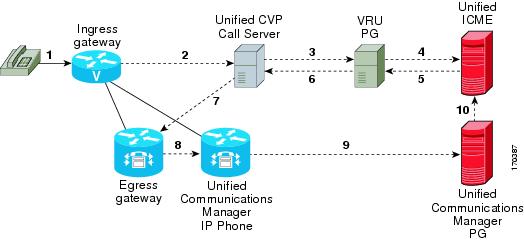
The following figure shows the Type 8 VRU-Only call flow model for ICMH. The solid lines in this figure indicate voice paths and dashed lines indicate signaling paths.

Figure 12. Type 8 VRU-Only Call Flow Model for ICMH


Note


  • For simplicity, the figure does not illustrate a call flow model for redundancy and failover.

  • Two Network VRUs are configured:

    • One on the NAM (Type 8).

    • One on the CICM for the INCRP connection (Type 8).

  • Use the ICM Script Editor’s TranslationRouteToVRU node to connect the call to the Network VRU.


Set Up Type 8 VRU-Only Call Flow Model for ICME and ICMH

Procedure


Step 1

From the Operations Console (or the Unified CVP product CD), transfer the following script, configuration, and .wav files to the VoiceXML Gateway used for the VRU leg.

Transfer the following files:

  • bootstrap.tcl

  • handoff.tcl

  • survivabilty.tcl

  • bootstrap.vxml

  • recovery.vxml

  • ringtone.tcl

  • cvperror.tcl

  • ringback.wav

  • critical_error.wav

Step 2

Configure the VXML gateway base settings.

Step 3

Configure the VXML gateway service settings.

Step 4

Configure the ICM VRU Label.

Step 5

Define a Network VRU on Unified ICME or (for Unified ICMH) on the NAM and each CICM.

On the ICM Configuration Manager, the Network VRU Explorer tool, specify the following:

  • Type: 8

  • Name: cvpVRU

Note


Although any name will work, cvpVRU is used by convention, and is the example name referenced elsewhere in this document.

Step 6

Configure the Peripheral Gates (PGs) on Unified ICME or (for Unified ICMH) on each CICM.

  1. Configure each PG.

  2. Configure a peripheral for each Unified CVP ICM Service connected to each PG.

Use the ICM Configuration Manager, the PG Explorer tool. For each Unified CVP ICM Service connected to this PG, in the tree view pane, select the applicable PG and configure the following items:

Logical Controller tab:

  • Client Type: VRU

  • Name: A name descriptive of this PG

    Example: <location>_A for side A of a particular location

Peripheral tab:

  • Peripheral Name: A name descriptive of this Unified CVP peripheral

    Examples: <location>_<cvp1> or <dns_name>

  • Client Type: VRU

  • Select the checkbox: Enable Post-routing

Advanced tab:

  • From the Network VRU field drop-down list, select the name: cvpVRU

Routing Client tab:

  • Name: By convention, use the same name as the peripheral.

  • Client Type: VRU

Step 7

Configure a Service and Route for each VRU on Unified ICME or (for Unified ICMH) on each CICM.

Note


You can also use service arrays. Refer to the Unified ICME documentation set for more information.

Using the ICM Configuration Manager, the Service Explorer tool, specify the following:

  • Service Name: cvpVRU

  • Route Name: PeripheralName_cvpVRU

  • Peripheral Number: 2

    Must match the "Pre-routed Call Service ID" in the Call Server configuration on the ICM tab in the Operations Console

  • Select the checkbox: Enable Post-routing

Step 8

Define trunk groups.

Note


You must configure one Network Transfer Group and one associated Trunk Group for each VRU leg Unified CVP ICM Service.

Define and configure the network trunk group on Unified ICME or (for Unified ICMH) on each CICM.

Using the ICM Configuration Manager, the Network Trunk Group Explorer tool:

  1. Identify the network trunk group.

    • Network Trunk Group Name: A name descriptive of this trunk group

  2. For each Unified CVP ICM Service for the VRU leg, configure an associated trunk group.

    • Peripheral Name: A name descriptive of this trunk group

    • Peripheral Number: 200

      Must match the "Pre-routed Call Trunk Group ID" in the Call Server configuration on the ICM tab in the Operations Console

    • Trunk Count: Select Use Trunk Data from the drop-down list

    • Do not configure any trunks

Step 9

Define translation route(s).

Define and configure a Translation Route for each VRU Peripheral on Unified ICME or (for Unified ICMH) on each CICM.

On Unified ICME, ICM Configuration Manager, Translation Route Explorer tool:

  1. Define a Translation Route for each VRU Peripheral. Specify the following:

    Translation Route tab:

    • Set the Name field to the name of the target VRU peripheral. (This is by convention; this value must be unique in the enterprise)

    • Set the Type field to DNIS and select the Service defined in the previous step

  2. Configure translation route and label information for each VRU peripheral. Complete the following:

    Route tab:

    • Set the Name: by convention, this is the name of the target VRU peripheral, followed by the DNIS that this route will use, for example, MyVRU_2000

      This value must be unique in the enterprise

    • Service Name drop-down list, select: PeripheralName.cvpVRU

    Peripheral Target tab:

    • Enter the first DNIS that will be seen by the VRU that you will be using for this translation route.

      Note


      The DNIS pool used for each VRU peripheral must be unique

    • From the drop-down list, select a Network Trunk Group which belongs to the target VRU

    Label tab:

    • Enter the translation route label (which might or might not be the same DNIS you entered on the Peripheral Target tab)

    • Type: Normal

    • Routing Client: Select the NIC Routing Client

    You must create an additional label for each NIC routing client.

    Note


    Repeat the Route and corresponding Peripheral Target and Label information for each DNIS in the pool.

Step 10

Create VRU and routing scripts.

Create VRU scripts and routing scripts for IVR treatment and agent transfer on Unified ICME or (for Unified ICMH) on each CICM .

Using the ICM Script Editor tool, create the VRU scripts and routing scripts to be used for IVR treatment and agent transfer, as described in other sections of this manual and in the ICM manuals.

The VRU scripts are associated with the applicable Network VRU.

For example, cvpVRU

Use the ICM Script Editor’s TranslationRouteToVRU node to connect the call to the Network VRU.

Step 11

Configure the ECC variables on Unified ICME or (for Unified ICMH) on the NAM and each CICM.

Using the ICM Configuration Manager, create the ECC variables.

For more information, see Define Unified CVP ECC Variables.

Step 12

Configure dialed numbers and call types on Unified ICME or (for Unified ICMH) on the NAM and each CICM.

On Unified ICME, using the ICM Configuration Manager, configure dialed numbers and call types.

For more information, refer to ICM Configuration Guide for Cisco ICM Enterprise Edition.

Step 13

On Unified CM configure Unified CM.

For more information, refer to the Unified CM user documentation.

Step 14

Install and configure the Call Server(s).

Using the Operations Console, select Device Management > CVP Call Server and install and configure the Call Server(s).

Select the check boxes: ICM and IVR

For detailed information, refer to the Operations Console online help.

Step 15

Configure the ICM service.

Using the Operations Console, select Device Management > CVP Call Server > ICM tab. On each Unified CVP Call Server, configure the ICM Service by specifying the following required information:

  1. VRU connection port number.

    Set the VRU Connection Port to match the VRU connection Port defined in ICM Setup for the corresponding VRU peripheral gateway (PIM).

  2. Maximum Length of DNIS.

    Set the maximum length DNIS to a number which is at least the length of the translation route DNIS numbers.

    Example: if the Gateway dial pattern is 1800******, the maximum DNIS length is 10.

  3. Call service IDs: New Call and Pre-routed.

    Enter the new and pre-routed call service IDs. Configure the ports for both groups according to the licenses purchased, call profiles, and capacity by completing the required fields on this tab.

  4. Trunk group IDs: New Call and Pre-routed.

    • Enter the new and pre-routed call trunk group IDs

    • Configure the group number for the Pre-routed Call Trunk group. The group number must match the trunk group number in the Network Trunk group used for the translation route

    • Configure the number of ports according to the licenses purchased and capacity

    • Configure each of the numbers used for translation routes. (The "New Call" group is not used since the calls are being sent to the VRU (Unified CVP) after some initial processing by the NIC/Unified ICME)

  5. Dialed numbers used in the translation route.

    Add the dialed numbers in the DNIS field.

  6. Check the default values of the other settings and change, if desired.

Step 16

Configure the IVR Service.

In the Operations Console, select Device Management > CVP Call Server > IVR tab.

Check the default values and change, if desired.

Refer to the Operations Console online help for information about other settings you might want to adjust from their default values.

Step 17

(Optional) Configure the Reporting Server.

In the Operations Console, select Device Management > CVP Reporting Server > General tab:

  1. Configure the Reporting Server.

  2. Select a Call Server to associate with this Reporting Server.

  3. Check the default values of the Reporting properties and change, if desired.

For more information, refer to Reporting Guide for Cisco Unified Customer Voice Portal


Type 7 VRU-Only Call Flow Model Network VRU for ICMH

In this call flow model, Unified CVP is deployed as a Network VRU at the NAM. The Unified CVP IVR Service in the Operations Console works with the Voice Gateway to act as the VRU. The VRU voice treatment is provided at the Voice Gateway and can include ASR/TTS. (This call flow model is used when Unified CVP is connected to the NAM.)

The NIC interfaces to the TDM switch to transfer calls to Unified CVP for VRU treatment and to queue and transfer calls using a VRU Type 7 call flow.


Note


Use this call flow model only if the PSTN to which the NIC is connected can transport a Correlation ID when it transfers a call. If this is not the set up you are using, then use the Type 8 VRU-Only Call Flow Model for ICMH. The Unified CVP SIP Service is part of this call flow model.

The following figure shows the Type 7 VRU-only call flow model network VRU for ICMH. In the figure, solid lines indicate voice paths and dashed lines indicate signaling paths.

Figure 13. Type 7 VRU-Only Call Flow Model Network VRU for ICMH


Note


  • For simplicity, the figure does not illustrate a call flow model for redundancy and failover.

  • The numbers in the figure indicate call flow progression.

  • Set the Network VRU Type to Type 7. There is no difference between these two types except that Type 7 causes ICME to explicitly inform Unified CVP when it is about to transfer the call away from Unified CVP. (Most customers use Type 7.)

  • The Network VRU names (where applicable), correlation IDs, and the ECC variable configurations must be identical on the NAM and CICM. All Labels must also be duplicated, although their routing clients will be different.

  • Use the SendToVRU node of CICM Script Editor to connect the call to the Network VRU.


Set Up Type 3 or 7 VRU-Only Call Flow Model Network VRU for ICMH

Procedure


Step 1

Perform Steps 1 to 4 of the Set Up Type 8 VRU-Only Call Flow Model for ICME and ICMH procedure.

Step 2

Configure each PG.

On the NAM, ICM Configuration Manager, PG Explorer tool:

  1. Configure each PG to be used for the VRU Client leg.

  2. Configure a peripheral for each Unified CVP ICM Service to be used as a VRU leg connected to each PG.

    For each Unified CVP ICM Service connected to this PG, in the tree view pane, select the applicable PG.

    Logical Controller tab, configure:

    • Client Type: VRU

    • Name: A name descriptive of this PG

      For example: <location>_A for side A of a particular location

    Peripheral tab, configure:

    • Peripheral Name: A name descriptive of this VRU peripheral.

      For example: <location>_<cvp1> or <dns_name>

    • Client Type: VRU

    • Select the checkbox: Enable Post-routing

    Routing Client tab:

    • Name: By convention, use the same name as the peripheral.

    • Client Type: VRU

Step 3

Define a Network VRU and labels.

On the CICM, ICM Configuration Manager, Network VRU Explorer tool, define a Network VRU for the VRU leg and labels for reaching the NAM.

Specify the following:

  • Type: 3 or 7

  • Name: cvpVRU

    Note

     
    This name is used by convention. Although any name will do, since it is referenced elsewhere in this document, cvpVRU is assumed.
  • Define a Label for the NAM.

    • Label: Network routing number

    • Type: Normal

    • Routing client: Select the INCRP Routing Client from the drop-down list.

Step 4

Define a Network VRU and a label for each NIC.

On the NAM, ICM Configuration Manager, Network VRU Explorer tool, define a Network VRU and a label for each NIC that is using this VRU.

Specify the following:

  • Type: 3 or 7

  • Name: cvpVRU

    Note

     
    This name is used by convention. Although any name will work, since it is referenced elsewhere in this document, cvpVRU is assumed.
  • Define a Label for each NIC that is using this VRU:

    • Label: Network routing number

    • Type: Normal

    • Routing client: Select the Routing Client for that NIC from the drop-down list.

Note

 
Make sure the Network VRU label is identical in the NAM and CICM. The Network VRU Name must be identical as well to avoid confusion.

Step 5

If there will be Routing Scripts on the NAM, define a default Network VRU.

On the NAM, ICM Configuration Manager, System Information tool, in the General section:

  • Define the Default Network VRU: cvpVRU

Step 6

Define a default VRU.

On the CICM, ICM Configuration Manager, System Information tool, in the General section:

  • Define a default Network VRU: cvpVRU

Step 7

Create the VRU and routing scripts.

On the CICM, ICM Script Editor tool:

Create the VRU scripts and routing scripts to be used for IVR treatment and agent transfer, as described in other sections of this manual and in the Unified ICME manuals. The VRU scripts are associated with the applicable Network VRU, that is, cvpVRU.

Use the ICM Script Editor’s SendToVRU node to connect the call to the Network VRU.

Note

 
A RunVRU Script or Queue node is an "implicit" SendToVRU node, although error handling will be easier if the explicit "SendToVRU" node is used.

Step 8

Configure the ECC variables.

On the NAM and CICM, ICM Configuration Manager, configure the ECC variables.

For more information, see Define Unified CVP ECC Variables.

Step 9

Configure dialed numbers and call types.

On the NAM and CICM, ICM Configuration Manager, configure dialed numbers and call types.

For more information, refer to ICM Configuration Guide for Cisco ICM Enterprise Edition

Step 10

Define customers.

On the NAM and CICM, ICM Configuration Manager:
  1. If necessary, differentiate VRUs (Unified CVPs) based on dialed number.

  2. Define customers and their Network VRU.

For more information, see Common Configuration for Differentiating VRUs Based on Dialed Number.

Step 11

On Cisco Unified CM, configure Unified CM.

For more information, refer to the Unified CM user documentation.

Step 12

Install and configure the Call Server(s).

In the Operations Console, select Device Management > CVP Call Server.

Step 13

Configure the ICM Service for each Call Server.

In the Operations Console, select Device Management > CVP Call Server > ICM tab. For each Unified CVP Call Server, configure the ICM Service by specifying the following required information:
  1. VRU connection port number.

    Set the VRU Connection Port to match the VRU connection Port defined in ICM Setup for the corresponding VRU peripheral gateway (PIM).

  2. Set the maximum length DNIS to the length of the Network Routing Number.

    Example: if the Gateway dial pattern is 1800******, the maximum DNIS length is 10.

  3. Call service IDs: New Call and Pre-routed.

    Enter the new and pre-routed call service IDs. Configure the ports for both groups according to the licenses purchased, call profiles, and capacity by completing the required fields on this tab

  4. Trunk group IDs: New Call and Pre-routed.

    Enter the new and pre-routed call trunk group IDs. Configure the group number for the Pre-routed Call Trunk group. The group number must match the trunk group number in the Network Trunk group used for the translation route.

    Configure the number of ports according to the licenses purchased and capacity. Configure each of the numbers used for translation routes. (The "New Call" group is not used since the calls are being sent to the VRU (Unified CVP) after some initial processing by the NIC/Unified ICME.)

  5. Check the default values of other settings and change, if desired.

Step 14

Configure the IVR service.

In the Operations Console, select Device Management > CVP Call Server > IVR tab and configure the IVR Service.

Check the default values and change, if desired.

Refer to the Operations Console online help for information about other settings you might want to adjust from their default values.

Step 15

(Optionally) Configure the Reporting Server.

In the Operations Console, select Device Management > CVP Reporting Server > General tab and configure the Reporting Server.

  1. Configure the Reporting Server.

  2. Select a Call Server to associate with this Reporting Server.

  3. Check the default values of the Reporting properties and change, if desired.

    For more information, refer to Reporting Guide for Cisco Unified Customer Voice Portal available at https://www.cisco.com/c/en/us/support/customer-collaboration/unified-customer-voice-portal/products-user-guide-list.html.


Set Up sendtooriginator Setting in the SIP Service of a Call Server

For the Unified CVP Branch call flow model, incoming calls into the Unified CVP Call Server from a gateway can be automatically routed back to the originating gateway at the branch using the sendtooriginator setting in the SIP Service of the Call Server. This setting overrides sending the call to the outbound proxy or to any locally configured static routes on Unified CVP. If the label returned from Unified ICME for the Unified CVP transfer matches one of the configured patterns in the Unified CVP sendtoorginator settings, then the call is routed to the sip:<label>@<host portion from header of incoming invite> SIP URL.

Note


  • The setting on the IOS gateway for signaling forward unconditional is required only if ISDN call variables needs to be available in the Unified ICME scripting environment. If these call variables are not required, then this setting can be omitted. The setting makes the SIP INVITE message larger in terms of bytes due to the extra payload in the message body for GTD variables. If the packet size is significantly greater than 1300 bytes, then TCP transport may be used over UDP transport due to the possibility of a network fragmentation of messages. See the Operations Console online help for more information.
  • If the pattern matches the label returned from ICM, then the call is routed to the originating host derived from the incoming calls remote party ID header or contact header.

  • The call is sent to the origination gateway if the following statements are true:

    • The remote party ID header is present on the incoming SIP invite.

    • The user agent header of the INVITE indicates an IOS gateway.

    • The pattern matcher on the label is configured for send-to-origin.