Device Mobility
Available Languages
Table Of Contents
Device Mobility Related Settings
High Availability for Device Mobility
Capacity Planning for Device Mobility
Dial Plan Design Considerations
Device Mobility Considerations for Building Classes of Service
Uniform On-Net Dialing Using the Line/Device Approach
Variable Length On-Net Dialing with Partitioned Addressing Using the Line/Device Approach
Variable Length On-Net Dialing with Flat Addressing Using the Line/Device Approach
Design Considerations for Using a VPN
Design Considerations for Device Mobility
Device Mobility
Revised: April 2, 2010; OL-21733-02
In Cisco Unified Communications Manager (Unified CM), a site or a physical location is identified using various settings such as locations, regions, calling search spaces, and media resources. Cisco Unified IP Phones residing in a particular site are statically configured with these settings. Unified CM uses these settings for proper call establishment, call routing, media resource selection, and so forth. However, when mobile phones such as Cisco IP Communicator or Cisco Unified Wireless IP Phones are moved from their home site to a remote site, they retain the home settings that are statically configured on the phones. Unified CM then uses these home settings on the phones in the remote site. This situation is undesirable because it can cause problems with call routing, codec selection, media resource selection, and other call processing functions.
Cisco Unified CM uses a feature called Device Mobility, which enables Unified CM to determine if the IP phone is at its home location or at a roaming location. Unified CM uses the device's IP subnets to determine the exact location of the IP phone. By enabling device mobility within a cluster, mobile users can roam from one site to another, thus acquiring the site-specific settings. Unified CM then uses these dynamically allocated settings for call routing, codec section, media resource selection, and so forth.
The features and functionality discussed in this chapter apply to all Cisco Unified Communications call processing deployment models unless otherwise noted.
This chapter begins with a discussion surrounding the main purpose for the Device Mobility feature, followed by an in-depth discussion of the Device Mobility feature itself. This discussion covers the various components and configuration constructs of the Device Mobility feature. This is followed by discussions pertaining to concerns regarding high availability and scalability of the Device Mobility feature. Next the chapter presents an in-depth discussion of the impact of the Device Mobility feature on the enterprise dial plan, including the implication for various dial plan models. The chapter concludes with a summarized list of design considerations and guidelines for deploying Device Mobility.
This chapter contains the following sections:
•
High Availability for Device Mobility
•
•
•
What's New in This Chapter
Table 20-1 lists the topics that are new in this chapter or that have changed significantly from previous releases of this document.
Need for Device Mobility
This section explains the need for device mobility when there are many mobile users in a Unified CM cluster.
Figure 20-1 illustrates a hypothetical network containing a Unified CM cluster without the Device Mobility feature, located at the headquarter site (HQ). The cluster has two remote sites, Branch1 and Branch2. All intra-site calls use G.711 voice codecs, while all inter-site calls (calls across the IP WAN) use G.729 voice codecs. Each site has a PSTN gateway for external calls.
Figure 20-1 Example Network with Two Remote Sites
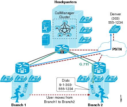
When a user in Branch1 moves to Branch2 and calls a PSTN user in Denver, the following behavior occurs:
•
•
•
Device Mobility Architecture
The Unified CM Device Mobility feature helps solve the problems mentioned above. This section briefly explains how the feature works. However, for a detailed explanation of this feature, refer to the product documentation available on http://www.cisco.com.
Some of the device mobility elements include:
•
•
•
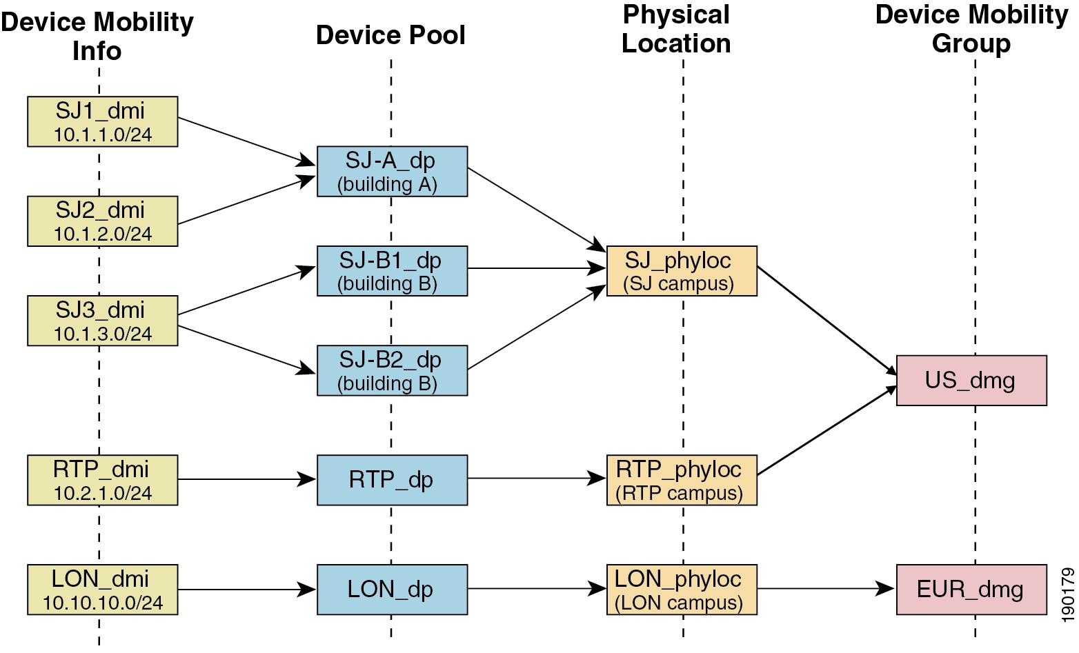
Figure 20-2 illustrates the relationship between all these terms.
Figure 20-2 Relationship of Device Mobility Components
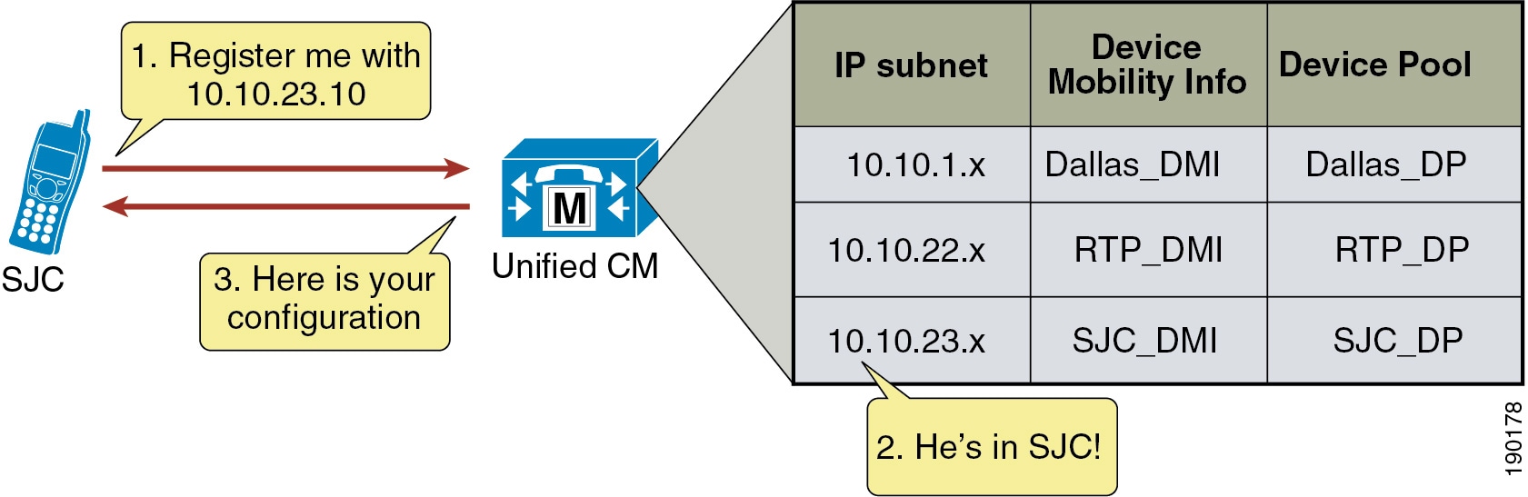
Unified CM assigns a device pool to an IP phone based on the device's IP subnet. The following steps, illustrated in Figure 20-3, describe the behavior:
1.
2.
3.
Figure 20-3 Phone Registration Process
Unified CM uses a set of parameters under the device pool configuration to accommodate Device Mobility. These parameters are of the following two main types:
•
Roaming Sensitive Settings
The parameters under these settings will override the device-level settings when the device is roaming within or outside a Device Mobility Group. The parameters included in these settings are:
•
•
•
•
•
•
•
•
The roaming sensitive settings primarily help in achieving proper call admission control and voice codec selection because the location and region configurations are used based on the device's roaming device pool.
For more details on various call admission control techniques, see the chapter on Call Admission Control, page 11-1.
The roaming sensitive settings also update the media resource group list (MRGL) so that appropriate remote media resources are used for music on hold, conferencing, transcoding, and so forth, thus utilizing the network efficiently.
The roaming sensitive settings also update the Survivable Remote Site Telephony (SRST) gateway. Mobile users register to a different SRST gateway while roaming. This registration can affect the dialing behavior when the roaming phones are in SRST mode.
For example, if a user moves with their phone to a new location that loses connectivity to Unified CM, then based on the roaming sensitive Device Mobility settings, a new SRST reference is configured for the moved phone and the moved phone will now be under control of the local roaming location SRST router. When this occurs, not only would the user's phone be unreachable from the PSTN or other sites because the device's DID will not have changed and will still be anchored at their home location, but in addition reachabililty from devices within the local failed site might be difficult without the use of abbreviated dialing as implemented within SRST.
As an example, assume that a user moves a phone from their home location in San Jose, which has a directory number of 51234 and an associated DID of 408 555 1234 to a remote location in New York, and that the link between the New York site and San Jose fails shortly after the user roams to the New York location. In this scenario the phones in the New York site will all fail-over to the SRST router in that site. The roaming/moved phone will also register to the New York SRST router because its SRST reference was updated based on the device mobility roaming sensitive settings. In this scenario, the local New York devices will register to the SRST router with five-digit extensions just as they do to Unified CM, and as a result the roaming phone still has a directory number of 51234. To reach the roaming phone from all other sites and from the PSTN, the number 408 555 1234 will be routed to the San Jose PSTN gateway to which this particular DID is anchored. Because the New York site is disconnected from the San Jose site, any such calls will be routed to the users' voicemail boxes since they will be unreachable at their desk phones. Likewise, calls internally within the local failed site will have to be dialed using five-digit abbreviated dialing or based on the configured digit prefixing as defined by the dialplan-pattern and extension-length commands within the SRST router. In either case, local callers will have to be understand the required dialing behavior for reaching the local roaming device by abbreviated dialing. In some cases this may be simply five-digit dialing or it may be that users have to dial a special digit prefix to reach the local roaming phone. The same logic applies to outbound dialing from the moved or roaming phone in New York because its dialing behavior might have to be altered in order to reach local extensions using abbreviated dialing. Outbound dialing to the PSTN from the local roaming device should remain the same, however.
Device Mobility Related Settings
The parameters under these settings will override the device-level settings only when the device is roaming within a Device Mobility Group. The parameters included in these settings are:
•
•
•
•
•
The device mobility related settings affect the dial plan because the calling search space dictates the patterns that can be dialed or the devices that can be reached.
Device Mobility Group
Device Mobility Group, as explained earlier, defines a logical group of sites with similar dialing patterns (for example, sites having the same PSTN access codes and so forth). With this guideline, all sites have similar dialing patterns in the site-specific calling search spaces. Sites having different dialing behavior are in a different Device Mobility Group. As illustrated in Figure 20-2, the San Jose and RTP sites' Device Mobility Info, Device Pools, and Physical Locations are different; however, all of these have been assigned to the same Device Mobility Group US_dmg because the required dialing patterns and PSTN access codes are the same between the two locations. On the other hand, the London site is assigned to a separate Device Mobility Group EUR_dmg due to the fact that the required dialing patterns and PSTN access codes there are different than those of the US sites. A user roaming within a Device Mobility Group may preserve his dialing behavior at the remote location even after receiving a new calling search space. A user roaming outside the Device Mobility Group may still preserve his dialing behavior at the remote location because he uses his home calling search space.
However, if a Device Mobility Group is defined with sites having different dialing patterns (for example, one site requires users to dial 9 to get an outside line while another site requires users to dial 8 to get an outside line), then a user roaming within that Device Mobility Group might not preserve his same dialing behavior at all locations. A user might have to dial digits differently at different locations after receiving a new calling search space at each location. This behavior can be confusing for users, therefore Cisco recommends against assigning sites with different dialing patterns to the same Device Mobility Group.
Device Mobility Operation
The flowchart in Figure 20-4 represents the operation of the Device Mobility feature.
Figure 20-4 Operation of the Device Mobility Feature
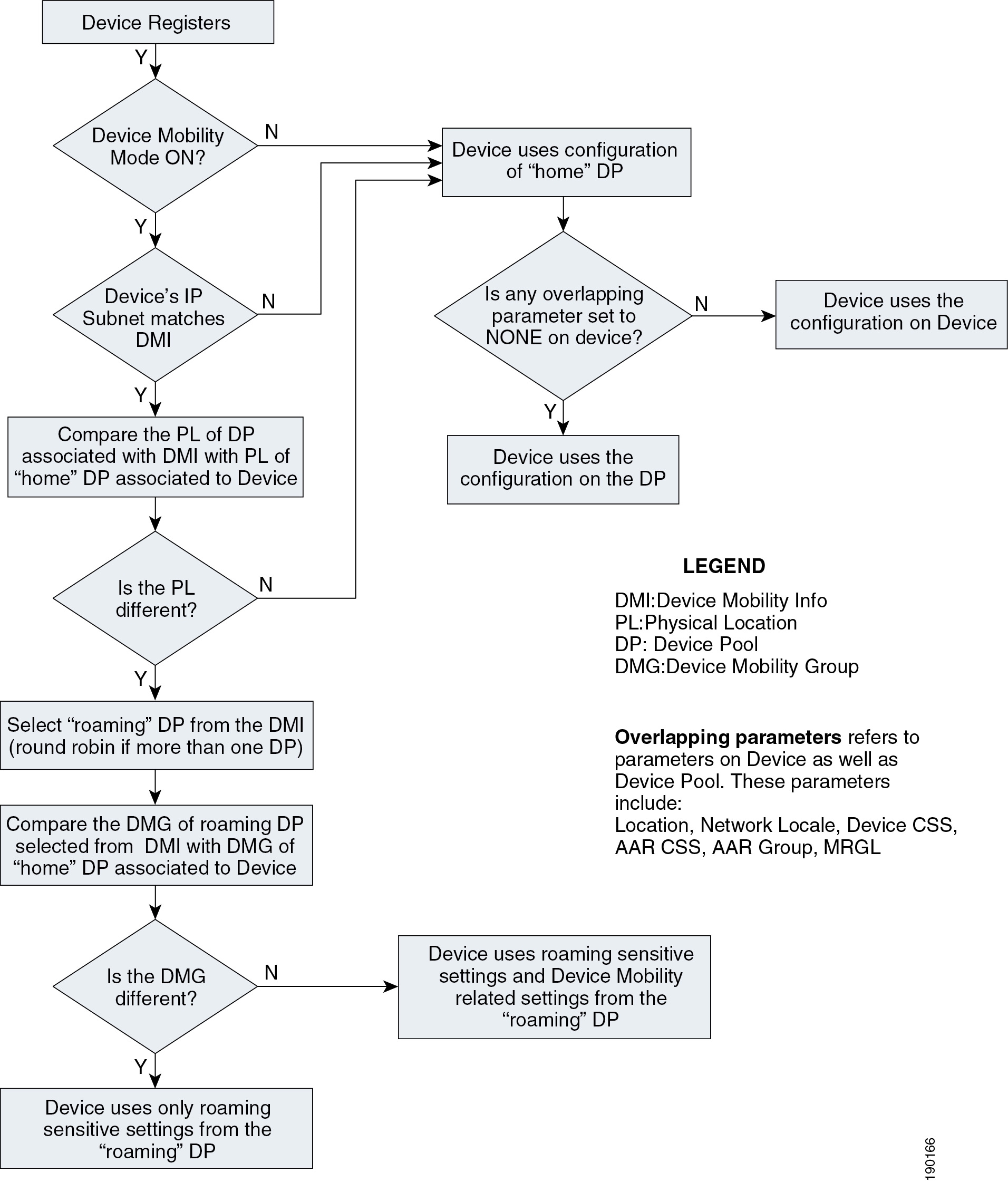
The following guidelines apply to the Device Mobility feature:
•
•
•
•
High Availability for Device Mobility
The Device Mobility feature is natively integrated with Unified CM, therefore the failure of a cluster node should have no impact on the functionality of Device Mobility. Device pool, Device Mobility Info, Device Mobility Group, and all other configurations surrounding Device Mobility are preserved if there is a failure of the publisher node or a call processing (subscriber) node. Additionally, if there is a call processing node failure, affected phones will fail-over to their secondary call processing node or SRST reference router as usual based on the Unified CM Group construct.
Capacity Planning for Device Mobility
There are no specific or enforced capacity limits surrounding the Device Mobility feature and the various configuration constructs (device pools, device mobility groups, and so forth) of the feature. However, as with many of the features and functions provided by Unified CM, configuration of these constructs does have sizing implications for the overall system. To ensure proper sizing of your system, use the Cisco Unified Communications Sizing Tool (Unified CST) to determine the system capacity based on everything from number of device pools and busy hour call attempt (BHCA) rates to number of phones and CTI applications deployed. While the sizing tool does not specifically address Device Mobility sizing, the overall sizing guidance provided by the tool will ensure that this feature as well as the overall system is deployed within supported capacity limits. Unified CST is available to Cisco employees and partners (with appropriate login account required) at http://tools.cisco.com/cucst.
Dial Plan Design Considerations
When using the Device Mobility feature, the dialing behavior of the phone depends on the roaming (or home) location of a phone. As discussed earlier, the device mobility related settings within the device pool affect the call flow behavior because the calling search space dictates the reachability of destination patterns within Unified CM. This section discusses several dial plan approaches for Device Mobility.
For detailed explanations of various dial plan approaches, see the chapter on Dial Plan, page 9-1.
Device Mobility Considerations for Building Classes of Service
Typically, a mobile user should have the same calling privileges while he is roaming as he would have at his home location. The chapter on Dial Plan, page 9-1, discusses two approaches for building classes of service: Traditional Approach, and Line/Device Approach.
Traditional Approach
With the traditional approach, both path selection and class of service are determined by the device-level calling search space. With the line/device approach, path selection is determined by the device-level calling search space and class of service is determined by the line-level calling search space. For all deployments, the line/device approach is recommended for building classes of service. In particular with deployments utilizing Device Mobility, it is important to use the line/device approach because this approach ensures that all calls made by a mobile device will use the roaming site or local gateway rather than the home site gateway. While the traditional approach can certainly be used, this chapter covers only the recommended line/device approach. For a general discussion of the traditional approach, see the chapter on Dial Plan, page 9-1.
Line/Device Approach
Unified CM concatenates the line and device calling search spaces for a given IP phone. The following key concepts apply to the line/device approach:
•
•
With the Device Mobility feature, the device calling search space is dynamically associated to the phone based on its location. The key concept of the line/device remains the same when using Device Mobility. The line calling search space provides the class-of-service information, while the roaming or home device calling search space that is selected provides the call routing information.
Figure 20-5 shows an example of building classes of service with the line/device approach when using Device Mobility in a cluster.
Figure 20-5 Line/Device Approach to Building Classes of Service
Cisco recommends using the line/device approach for building classes of service. This model has significant advantages when using Device Mobility because it greatly reduces the number of device pools needed, as indicated by the following formula:
Total device pools = (Number of sites)
The following design considerations apply to this approach:
•
•
•
Choosing a Dial Plan Model
As discussed in the chapter on Dial Plan, page 9-1, there are three main approaches for the dial plan model:
•
•
•
The following sections present various dial plan models combined with an approach for building classes of service.
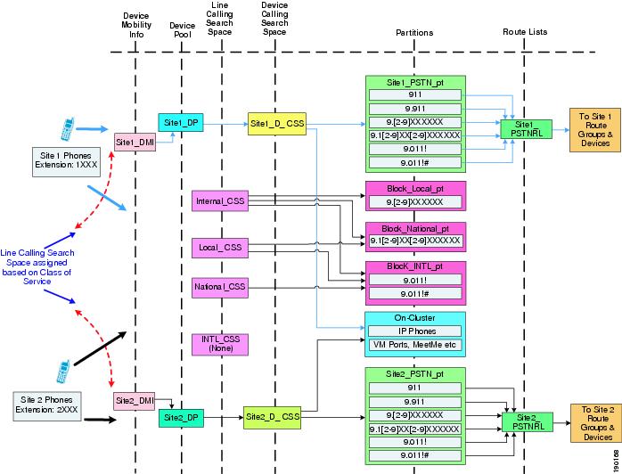
Uniform On-Net Dialing Using the Line/Device Approach
Figure 20-6 shows a uniform on-net dial plan for Device Mobility.
Figure 20-6 Uniform On-Net Dial Plan for Device Mobility
This is the most basic dial plan model, and it has the following characteristics:
•
•
•
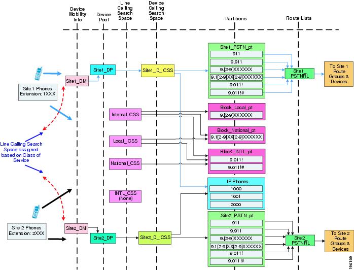
Variable Length On-Net Dialing with Partitioned Addressing Using the Line/Device Approach
Figure 20-7 shows a variable-length on-net dial plan with partitioned addressing for Device Mobility.
Figure 20-7 Variable-Length On-Net Dial Plan with Partitioned Addressing for Device Mobility
The following design considerations apply to the dial plan model in Figure 20-7:
•
•
•
•
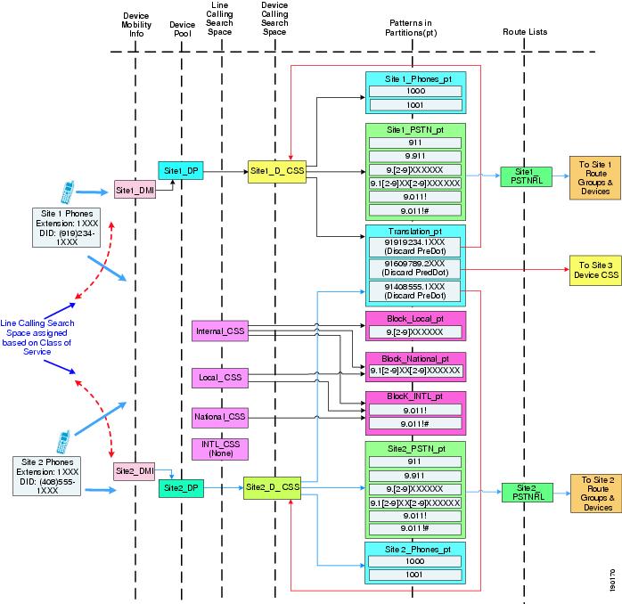
Variable Length On-Net Dialing with Flat Addressing Using the Line/Device Approach
Figure 20-8 shows a variable-length on-net dial plan with flat addressing for Device Mobility.
Figure 20-8 Variable-Length On-Net Dial Plan with Flat Addressing for Device Mobility
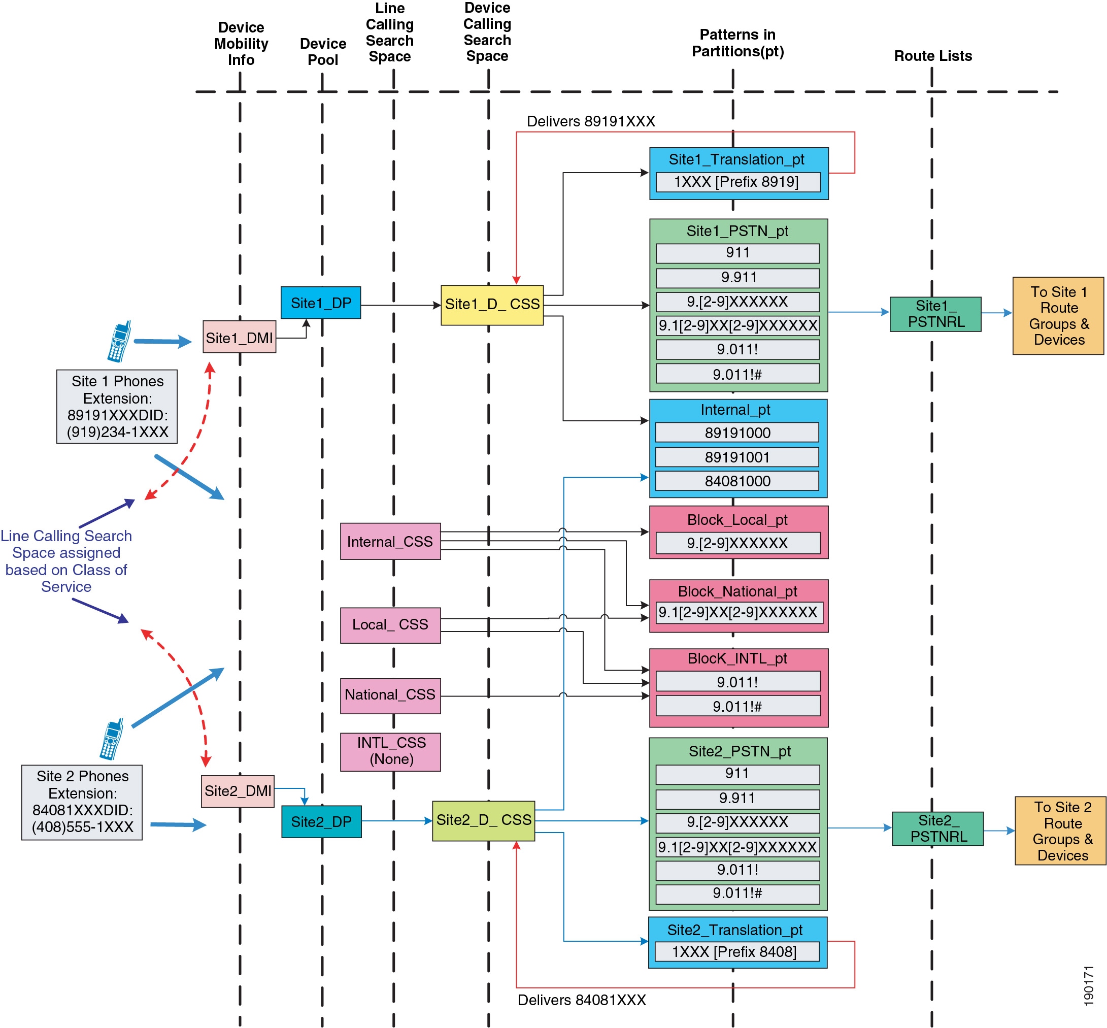
The following design considerations apply to the dial plan model in Figure 20-8:
•
•
•
Design Considerations for Using a VPN
This section briefly explains the design guidelines for enabling the Device Mobility feature for IP software phones or Cisco IP Communicator. Many users may have software-based phones or hardware phones running VPN client software that connect to the Unified CM cluster using a virtual private network (VPN) connection over the internet.
For information on deploying a VPN, refer to the various VPN design guides available under the Security in WAN subsection of the Design Zone for WAN/MAN, available at:
http://www.cisco.com/en/US/solutions/ns340/ns414/ns742/ns817/landing_wan_security.html
Figure 20-9 shows an example of an IP software phone user connected over a VPN to the Unified CM cluster.
Figure 20-9 VPN Connection to Cisco IP Communicator
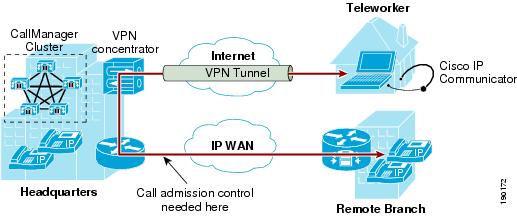
VPN users must adhere to the following guidelines:
•
•
•
These guidelines ensure that call admission control is correctly applied on the enterprise WAN.
Design Considerations for Device Mobility
Observe the following design recommendations when deploying Device Mobility:
•
•
•
•
•
•
•
•
 Feedback
Contact Cisco
- Open a Support Case

- (Requires a Cisco Service Contract)
This Document Applies to These Products
- Collaboration Endpoints - Retired Products
- Conferencing - Retired Products
- Contact Center - Retired Products
- Optical Networking - Retired Products
- Routers - Retired Products
- Security - Retired Products
- Servers - Unified Computing (UCS) Retired Products
- Storage Networking Retired Products
- Switches - Retired Products
- Video - Retired Products
- Wireless - Retired Products