Configuring ATM SVCs, PNNI Routing, and SPVCs
Available Languages
Table Of Contents
Configuring ATM SVCs, PNNI Routing, and SPVCs
Modifying Port Parameters After AutoConfiguration
Preconfiguring an UNI Port with AutoConfiguration
Configuring a Port Without AutoConfiguration and Without ILMI
Preconfiguring a NNI Trunk with AutoConfiguration
Configuring Virtual Trunk on a BXM Port
Enabling VSI ILMI Functionality on Line (Port) Interfaces
Enabling VSI ILMI Functionality on Physical Trunk Interfaces
Enabling VSI ILMI Functionality on Virtual Trunk Interfaces
Viewing VSI ILMI Functionality on Interfaces
Set Peer Group Leader Parameters
Set Locally Reachable Address(es)
SVC without ILMI Address Registration
SVC with ILMI Address Registration
Configuring SPVC Stat Collection
Configuring ATM SVCs, PNNI Routing, and SPVCs
Use this chapter to find out about the tasks typically performed to bring up the SES PNNI node. This chapter assumes the following:
•
You have completed and verified the hardware installation at the BPX and the SES PNNI Controller, as described in Chapter 5 of the Cisco SES Hardware Installation Guide.
•
After completing the installation and initial configuration tasks, you are ready to bring up the system, using the task sequence shown in Figure 10-1.
Figure 10-1
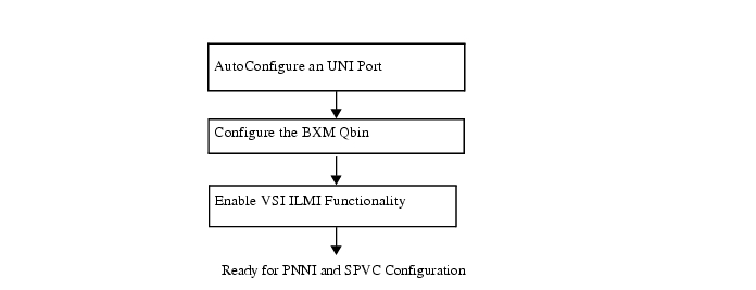
Bringup Tasks for PNNI Controller
This chapter refers to commands that run from the BPX CLI, the SES CLI or CiscoView menus. The BPX CLI commands are documented in detail in the Cisco WAN Switching Command Reference, Release 9.2. The CiscoView menus are described in Chapter 11, "Network Management."
UNI Configuration
Use this section to find out how to use auto-configuration on the PNNI Controller, to set default PNNI values and ILMI address registration on UNI ports.

Note
Auto-configuration is comprised of AutoConfigure an UNI Port
AutoConfigure an UNI Port
Use the following procedure to connect an ATM UNI for auto-configuration using ILMI address registration and the VSI protocol.
At the BPX CLI, perform the following steps:
Step 1
Make sure the ATM CPE is configured for ILMI.
Step 2
upln slot.port
Step 3
upport slot.port
Step 4
cnfvsiif slot.port 2
Step 5
A system response similar to the following example occurs:
----------------------------------------------------------------------------
oriobpx3 TN StrataCom BPX 8620 9.2.3U Feb. 16 2000 21:39 PST
Port/Trunk :1.3
Maximum PVC LCNS: 256 Maximum PVC Bandwidth:2207
Partition 1
Partition State : Enabled
Minimum VSI LCNS: 2000
Maximum VSI LCNS: 7000
Start VSI VPI: 1
End VSI VPI : 255
Minimum VSI Bandwidth : 100000 Maximum VSI Bandwidth : 250000
VSI ILMI Config : 0
Last Command:cnfrsrc 1.3 256 2207 y 1 e 2000 7000 1 255 100000 250000
-------------------------------------------------------------------------------
Note
Step 6
example for ILMI port configuration on a BXM card:
cnfport 1.3 N H i 0 16 y y n 30 3 4 N N y
-------------------------------------------------------------------------
oriobpx1 TN StrataCom BPX 8620 9.2.3U Feb. 3 2000 18:12 PST
Port: 1.3 [ACTIVE ]
Interface: LM-BXM CAC Override: Enabled
Type: UNI %Util Use: Disabled
Shift: SHIFT ON HCF (Normal Operation)
SIG Queue Depth: 640 Port Load: 0 %
Protocol: ILMI Protocol by Card: Yes
VPI.VCI: 0.16 Addr Reg Enab: Y
ILMI Polling Enabled: Y
Trap Enabled: N
T491 Polling Interval: 30
N491 Error Threshold: 3
N492 Event Threshold: 4
-------------------------------------------------------------------------
The BXM now sends a VSI trap to the SES PNNI controller.
When the SES PNNI controller receives the trap, it sends a VSI passthrough back to the BXM to enable auto-configuration. The information in the passthrough includes auto-configuration default parameters. Auto-configuration parameters include details such as autoconfiguration on, service registry on, address registration on, node prefix, and others.
The BXM then starts the ILMI protocol with the attached ATM CPE. The BXM will then send the SES PNNI controller the port information: vpi/vci range, interface type, device type, ILMI version, and UNI Signaling version.
Finally, the PNNI Controller starts the UNI signaling stacks.
Note
Modifying Port Parameters After AutoConfiguration
To modify port parameters after AutoConfiguration, perform the following steps at the SES PNNI Controller CLI:
Note
Use the following procedure to modify port parameters.
Step 1
This brings down the signaling stacks for the port.
Step 2
•
•
•
•
•
Non-service affecting parameters can be changed without downing the port. For example, you do not need to down the port to execute the following SES CLI commands:
•
•
•
•
Step 3
•
•
•
•
•
•
•
Step 4
Preconfiguring an UNI Port with AutoConfiguration
Use the following procedure to preconfigure specific parameters before a port is brought up with AutoConfiguration.
Use the SES PNNI Controller CLI to perform steps 1 through 3.
Step 1
Note
Step 2
•
•
•
•
•
Step 3
Note
Use the BPX CLI to perform steps 4 through 8.
Step 4
Step 5
Step 6
Step 7
Step 8
The following results occur:
a.
b.
•
•
Configuring a Port Without AutoConfiguration and Without ILMI
If the attached ATM CPE does not support ILMI, you must bring up the port without auto-configuration.
Use the BPX CLI to perform steps 1 through 4.
Step 1
Step 2
Step 3
Step 4
The following results occur:
a.
b.
Use the SES PNNI Controller CLI to perform step 5.
Step 5
Note
NNI Trunk Configuration
Use this section to find out how to configure a PNNI trunk on BPX and SES PNNI Controller.
AutoConfigure an NNI Trunk
Use the following procedure to connect an ATM NNI trunk with auto-configuration using ILMI and the VSI protocol.
At the BPX CLI, perform the following steps:
Step 1
Make sure the other BPX BXM port is configured for ILMI.
Step 2
uptrk slot.port
Step 3
addtrk slot.port
Since AutoRoute is needed to provide IP connectivity, Time of Date, and Network Clocking for this release of BPX/SES, it is essential to add AutoRoute partition in a trunk even if there is no "AutoRoute" PVC service to be implemented. Limit resource is needed to be provisioned to carry IP connectivity, Time of Date, and Network Clocking. Notice that when the AutoRoute service is added to the trunk, the VPI = 0 and 1 will be reserved for AutoRoute. The available VPI for VSI (or PNNI) will start from
VPI = 2.Step 4
cnfvsiif slot.port 3
Step 5
A system response similar to the following example occurs:
oriobpx1 TN StrataCom BPX 8620 9.2.3U Feb. 16 2000 21:33 PST
Port/Trunk :1.2
Maximum PVC LCNS: 256 Maximum PVC Bandwidth:2207
(Statistical Reserve:1000)
Partition 1
Partition State : Enabled
Minimum VSI LCNS: 3000
Maximum VSI LCNS: 7000
Start VSI VPI: 2
End VSI VPI : 4095
Minimum VSI Bandwidth : 100000 Maximum VSI Bandwidth : 350000
VSI ILMI Config : 0
Last Command:cnfrsrc 1.2 256 2207 y 1 e 3000 7000 2 4095 100000 350000
Note
Step 6
example for ILMI port configuration on a BXM card:
----------------------------------------------------------------------------oriobpx3 TN StrataCom BPX 8620 9.2.3U Feb. 17 2000 08:22 PST
TRK 1.2 Config OC3 [353207cps] BXM slot: 1
Transmit Rate: 353208 VPC Conns disabled: No
Protocol By The Card: Yes Line framing: STS-3C
VC Shaping: No coding: --
Hdr Type NNI: Yes recv impedance: --
Statistical Reserve: 1000 cps cable type: --
Idle code: 7F hex length: --
Connection Channels: 256 Pass sync: No
Traffic:V,TS,NTS,FR,FST,CBR,N&RT-VBR,ABR Loop clock: No
SVC Vpi Min: 0 HCS Masking: Yes
SVC Channels: 0 Payload Scramble: Yes
SVC Bandwidth: 0 cps Frame Scramble: Yes
Restrict CC traffic: No Virtual Trunk Type: --
Link type: Terrestrial Virtual Trunk VPI: --
Routing Cost: 10 Deroute delay time: 0 seconds
Last Command:cnftrk 1.2 353208 y Y 1000 7F V,TS,NTS,FR,FST,CBR,NRT-VBR,ABR,RT-V BR N TERRESTRIAL 10 0 N N Y Y Y N
----------------------------------------------------------------------------
Step 7
cnfvsipart slot.port partition_id Enable_ilmi [y/n]
Example:
----------------------------------------------------------------------------
oriobpx3 TN StrataCom BPX 8620 9.2.3U Feb. 17 2000 08:25 PST
Trunk:1.2 Partn:1 ILMI:E LCN:1 Topo:BPX NW IP
Last Command: cnfvsipart 1.2 1 y
-------------------------------------------------------------------------------
The BXM now sends a VSI trap to the SES PNNI controller.
When the SES PNNI controller receives the trap, it sends a VSI passthrough back to the BXM to enable auto-configuration. The information in the passthrough includes auto-configuration default parameters.
The BXM then starts the ILMI protocol with the attached BXM port. The BXM will then send the SES PNNI controller the port information: vpi/vci range, interface type, device type, ILMI version, and NNI Signaling version.
Finally, the PNNI Controller starts the PNNI signaling stacks.
Note that all ILMI features on SES PNNI are default to be on, there is NO need to use cnfautocnf to enable ILMI features on SES PNNI.
Step 8
Example:
----------------------------------------------------------------------------
oriobpx3 TN StrataCom BPX 8620 9.2.3U Feb. 17 2000 08:29 PST
Trunk:1.2 Partn:1 ILMI:E LCN:1 Topo:BPX NW IP
Trunk:1.2 Partn:2 -- VSI partition DISABLED
Trunk:1.2 Partn:3 -- VSI partition DISABLED
Sys_Id generated = 38.33.39.33.36.33
Last Command: dspvsipartcnf 1.2
----------------------------------------------------------------------------
Preconfiguring a NNI Trunk with AutoConfiguration
Use the following procedure to preconfigure specific parameters before a trunk is brought up with AutoConfiguration.
Use the SES PNNI Controller CLI to perform steps 1 through 3.
Step 1
Note
Step 2
•
•
•
Note
Step 3
Note
Use the BPX CLI to perform steps 4 through 8.
Step 4
Step 5
Step 6
Step 7
Step 8
Step 9
The following results occur:
a.
b.
•
•
Configuring Virtual Trunk on a BXM Port
Use the BPX CLI to configure VSI on BXM ports or trunks. For more information about the VSI protocol, see Appendix D, "Virtual Switch Interface."
A default Service Class Template is assigned to a logical interface when the interface is upped using the upport and uptrk commands.
For example:
•
•
•
In the above example, the default template has the identifier of 1. You can change the default Service Class Template—from Service Class Template 1—to another Service Class Template by using the cnfvsiif command. Use the dspvsiif command to view a template associated with a specified interface.
For example:
•
•
•
•
The cnfvsiif command assigns a selected Service Class Template to an interface (VI) by specifying the template number.:
cnfvsiif <slot.port.vtrk> <tmplt_id>
The dspvsiif command presents the type of Service Class Template assigned to an interface (VI)
dspvsiif <slot.port.vtrk>
Configure the BXM Qbin
The default Service Class Template is assigned to the interface (VI) when an interface (VI) is activated by the uptrk or upport commands. The corresponding Qbin template is then copied into the data structure of that interface at the BXM.
You can change some of the Qbin parameters by using the cnfqbin command. The Qbin is now "user configured" as opposed to "template configured." This information may be viewed on the dspqbin screen.
Qbin dependencies
The available Qbin parameters are shown in Table 10-1.
Qbins available for VSI are restricted to Qbins 10-15 for that interface.
All 32 possible virtual interfaces are provided with 16 Qbins.
Additional Service Class Template commands are described in Table 10-2.
Table 10-2
Service Class Template Commands
Enable VSI ILMI Functionality
Currently, VSI ILMI functionality can be enabled both on line (port) interfaces and trunk interfaces. VSI ILMI functionality cannot be enabled on trunks to which feeders or VSI controllers are attached.
Enabling VSI ILMI Functionality on Line (Port) Interfaces
The following commands enable VSI ILMI Functionality on specified line or port.
•
•
•
•
Enabling VSI ILMI Functionality on Physical Trunk Interfaces
The following commands enable VSI functionality on specified trunk interfaces.
•
•
•
•
Enabling VSI ILMI Functionality on Virtual Trunk Interfaces
The following commands enable VSI ILMI functionality on virtual trunk interfaces.
•
•
•
Note
•
Note
Viewing VSI ILMI Functionality on Interfaces
The following command enables view of the current VSI ILMI functionality on a specified interface.
•
Configuring PNNI
The recommended configuration sequence for each SES PNNI node in the switched system is outlined in Figure 10-2.
All tasks are configurable using the SES PNNI Controller CLI. Some of the tasks, as indicated in Figure 10-2, can be configured using CiscoView.
Figure 10-2
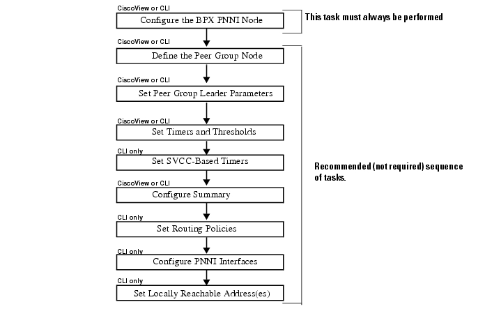
PNNI Configuration Sequence Overview
For more information about:
•
•
•
Configure the BPX PNNI Node
Use the commands in this section to set up the PNNI Node, and to set the following node parameters:
•
•
•
•
•
•
•
•
Syntax Descriptions
addpnni-node <node-index>
cnfpnni-node <node-index>
Before changing a node index configuration, node index must be disabled. Use
cnfpnni-node <node-index> -enable false to disable the node index, and use
cnfpnni-node <node-index> -enable true to enable the node index.
Use dsppnni-node <node-index> to display a PNNI node configuration.
Example:
----------------------------------------------------------------------------
orioses1.1.1.PXM.a > dsppnni-node 1
node index: 1 node name:
Level............... 56 Lowest.............. true
Restricted transit.. off Complex node........ off
Branching restricted on
Admin status........ up Operational status.. up
Non-transit for PGL election.. off
Node id...............56:160:47.00918100000000d058ac26b6.00d058ac26b6.01
ATM address...........47.00918100000000d058ac26b6.00d058ac26b6.01
Peer group id.........56:47.00.9181.0000.0000.0000.0000.00
----------------------------------------------------------------------------
Related Commands
In CiscoView:
•
•
Set Peer Group Leader Parameters
Use the command in this section to set the following peer group leader parameters:
•
•
•
•
Syntax Description
cnfpnni-election <node-index> -<parameter> <number>
Example: set leadership priority
cnfpnni-election 1 -priority 1
Use dsppnni-election <node-index> to display peer group leader election set up.
Example:
-------------------------------------------------------------------------------
ORSES17.1.1.PXM.a > dsppnni-election 1
node index:1
PGL state...... OperPgl Init time(sec)....... 15
Priority....... 51 Override delay(sec).. 30
Re-election time(sec) 15
Pref PGL...............56:160:47.00918100000000d058ac2613.00d058ac2613.01
PGL....................56:160:47.00918100000000d058ac2613.00d058ac2613.01
Active parent node id..40:56:47.009181111111111111111111.00d058ac2613.00
----------------------------------------------------------------------------
In CiscoView:
•
•
Set Timers and Thresholds
Use the commands in this section to set the following parameters to define timers and thresholds for the PNNI node:
•
•
•
•
•
•
•
•
•
•
•
•
•
Syntax Description
cnfpnni-timer <node-index> -<parameter> <number>
Example: set PTSE refresh interval
orioses1.1.1.PXM.a > cnfpnni-timer 1 -ptseRefreshInterval 1000Use dsppnni-timer <node-index> to display timer set up:
Example:
----------------------------------------------------------------------------
orioses1.1.1.PXM.a > dsppnni-timer 1
node index:1
Hello holddown(100ms)... 10 PTSE holddown(100ms)... 10
Hello int(sec).......... 15 PTSE refresh int(sec).. 1000
Hello inactivity factor. 5 PTSE lifetime factor... 200
Retransmit int(sec)..... 5
AvCR proportional PM.... 50 CDV PM multiplier...... 25
AvCR minimum threshold.. 3 CTD PM multiplier...... 50
Peer delayed ack int(100ms)................... 10
Logical horizontal link inactivity time(sec).. 120
----------------------------------------------------------------------------
Related Commands
In CiscoView:
•
Set SVCC-Based Timers
Use the commands in this section to set the following SVCC-Based RCC-Timer parameters for the PNNI node:
•
•
•
•
Syntax Description
cnfpnni-svcc-rcc-timer <node-index>
Configure Summary Address(es)
Use the command in this section to set summary address parameters for the PNNI node.
Syntax Description
addpnni-summary-addr <node-index> address-prefix prefix-length
This command is not available in CiscoView.
Example:
orioses1.1.1.PXM.a > addpnni-summary-addr 1 47.0091.8100.0000.1111.2222 88Use dsppnni-summary-addr <node-index> to display summary addresses.
Example:
-------------------------------------------------------------------------------
orioses1.1.1.PXM.a > dsppnni-summary-addr 1
node index:1
Type.............. internal Suppress.............. false
State............. advertising
Summary address........47.0091.8100.0000.00d0.58ac.26b6/104
node index:1
Type.............. internal Suppress.............. false
State............. inactive
Summary address........47.0091.8100.0000.1111.2222/88
-------------------------------------------------------------------------------
Related Commands
In CiscoView:
•
Set Routing Policies
Use the commands in this section to set the following routing policy parameters for the lowest level PNNI node.
•
•
•
•
•
•
•
•
Syntax Description
cnfpnni-routing-policy
This command is not available in CiscoView
Configure PNNI Interfaces
Use the commands in this section to set the following PNNI interface parameters on the PNNI node:
•
•
•
Syntax Description
cnfpnni-intf <slot.port> -<parameter> <number>
This command is not available in CiscoView.
Example: configure CBR AW on an interface
orioses1.1.1.PXM.a > cnfpnni-intf 1.3 -awcbr 10000
Use dsppnni-intf <slot.port> to display an PNNI interface set up.
Example:
-------------------------------------------------------------------------------
orioses1.1.1.PXM.a > dsppnni-intf 1.3
Physical port id:1.3 Logical port id: 66304
Aggr token.......... 0 AW-NRTVBR........... 5040
AW-CBR.............. 10000 AW-ABR.............. 5040
AW-RTVBR............ 5040 AW-UBR.............. 5040
-------------------------------------------------------------------------------
Set Locally Reachable Address(es)
Use the commands in this section to set the following locally reachable address parameters for the lowest level PNNI node:
•
•
•
•
Syntax Description
dsppnni-reachable-addr <local/network>
Note
This command is not available in CiscoView.
Example:
----------------------------------------------------------------------------
orioses1.1.1.PXM.a > dsppnni-reachable-addr local
scope............... 0 port id............. -1
Exterior............ false
ATM addr prefix.....47.0091.8100.0000.00d0.58ac.26b6.0000.0001.0200/152
scope............... 0 port id............. -1
Exterior............ false
ATM addr prefix.....47.0091.8100.0000.00d0.58ac.26b6.0000.0001.0300/152
scope............... 0 port id............. -1
Exterior............ false
ATM addr prefix.....47.0091.8100.0000.00d0.58ac.26b6.0000.0001.0600/152
scope............... 0 port id............. -1
Exterior............ false
ATM addr prefix.....47.0091.8100.0000.00d0.58ac.26b6.0000.0001.0800/152
scope............... 0 port id............. -1
Exterior............ false
ATM addr prefix.....47.0091.8100.0000.00d0.58ac.26b6.00d0.58ac.26b6/152
orioses1.1.1.PXM.a > dsppnni-reachable-addr network
scope............... 0 Advertising node number 2
Exterior............ false
ATM addr prefix.....47.0091.8100.0000.0010.7bc1.54b5/104
Advertising nodeid..56:160:47.00918100000000107bc154b5.00107bc154b5.01
----------------------------------------------------------------------------
Show PNNI Link Hello Protocol
Use the commands in this section to display the following link and Hello related information:
•
•
•
•
•
•
•
•
•
•
•
•
•
•
Syntax Description
dsppnni-link [node-index [slot.port]]
Example:
----------------------------------------------------------------------------orioses3.1.1.PXM.a > dsppnni-link 1node index :1Local port id: 66048 Remote port id: 66048Type. lowestLevelHorizontalLink Hello state....... twoWayInsideDerive agg........... 0 Intf index........... 66048SVC RCC index........ 0 Hello pkt RX......... 1248753Hello pkt TX......... 1234565Remote node id.........56:160:47.00918100000000d058ac26b6.00d058ac26b6.01Upnode id..............0:0:00.000000000000000000000000.000000000000.00Upnode ATM addr........00.000000000000000000000000.000000000000.00Common peer group id...00:00.00.0000.0000.0000.0000.0000.00------------------------------------------------------------------------------Setting Up SVC
After setting up the UNI ports, NNI trunks, and PNNI, you are ready to setup SVC and SPVC in a network. This section will explain how to set up an SVC. A two-node network is used to describe the SVC set up procedure.
Figure 10-3 SVC Set Up Example
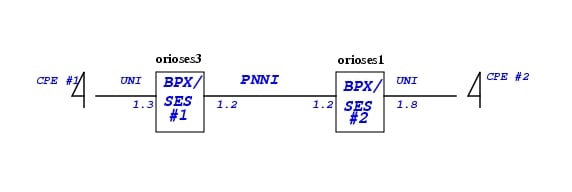
SVC without ILMI Address Registration
Assuming CPE #1 has ATM address:47.00918100000000d058ac26b6.000000010800.00
Assuming CPE #2 has ATM address:47.00918100000000107bc154b5.000000010300.00
Using the following procedures to set up addresses on orioses1 and orioses3 before place the SVC call.
Step 1
orioses3.1.1.PXM.a > addaddr 1.3 47.00918100000000d058ac26b6.000000010800.00 160
Add ATM summary address on orioses3:
orioses3.1.1.PXM.a > addpnni-summary-addr 1 47.00918100000000d058ac26b6 104
Step 2
orioses1.1.1.PXM.a > addaddr 1.8 47.00918100000000107bc154b5.000000010300.00 160
Add ATM summary address on orioses1:
orioses1.1.1.PXM.a > addpnni-summary-addr 1 47.00918100000000107bc154b5 104
Step 3
Step 4
Use dsppncons to display SVC connection between two nodes.
------------------------------------------------------------------------------orioses3.1.1.PXM.a > dsppnconsPort VPI VCI CallRef X-Port VPI VCI CallRef Type OAM-Type1.2 1 42 11 1.3 99 999 11 PTP YesCalling-Addr:47.00918100000000d058ac26b6.000000010800.00Called-Addr:47.00918100000000107bc154b5.000000010300.001.3 99 999 11 1.2 1 42 11 PTP YesCalling-Addr:47.00918100000000d058ac26b6.000000010800.00Called-Addr:47.00918100000000107bc154b5.000000010300.00------------------------------------------------------------------------------
SVC with ILMI Address Registration
Use the following procedures to setup SVC with ILMI address registration:
Step 1
Configure orioses1 UNI 1.8 with ILMI enabled (cnfport)
Make sure both CPE#1 and CPE#2 have ILMI turned on.
Step 2
orioses3.1.1.PXM.a > addprfx 1.3 47.00918100000000d058ac26b6orioses1.1.1.PXM.a > addprfx 1.8 47.00918100000000107bc154b5Step 3
Step 4
47.00918100000000d058ac26b6.00d058ac4021.00where 00d058ac4021 is the MAC addr of CPE#2
Configuring ATM SPVC
There are two ways to provision an SPVC: using CLI on PNNI Controller or using CWM. Using CWM to provision an SPVC will be documented in Network Management Chapter. This section will use a step-by-step example to illustrate how to use the PNNI Controller CLI to provision an SPVC.
Configuring Node Prefix
Before setting up SPVC, user should check if the SPVC Node Prefix has been configured or if the SPVC Node Prefix to be used for SPVCs. If it is not, use the following procedures to change it.
Use the "cnfspvcprfx" command to configure the Nodal SPVC Prefix
pswpop4.1.1.PXM.a > dspspvcprfx
SPVC Node Prefix: 47.00918100000000107bc15339
pswpop4.1.1.PXM.a > cnfspvcprfx -prfx 4700918100000000c043002ddf
pswpop4.1.1.PXM.a > dspspvcprfx
SPVC Node Prefix: 47.00918100000000c043002ddf
One can only configure an SPVC prefix when there is no connection on the node. The SPVC prefix must be unique across the network.
Add an SPVC Connection
Figure 10-4
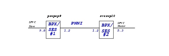
SPVC Setup Example
Reference to Figure 10-4 and use the following procedure to add an SPVC in a PNNI network.
Step 1
pswpop9.1.PXM.a > addcon 9.8 111 111 1 2
LOCAL ADDR: 4700918100000000C043002DDF00000009080000.111.111
The LOCAL ADDR is the slave endpoint ATM address to be used at the master endpoint to setup an SPVC to the slave endpoint. Please note, service_type is selected to be 1 i.e. CBR service. The mastership is 2=slave.
Use "dspcon" to show the slave endpoint configuration.
pswpop9.1.PXM.a > dspcon 9.8 111 111
Port Vpi Vci Owner State
-------------------------------------------------------------------------
Local 9:-1.8:-1 111.111 SLAVE FAIL
Address: 47.00918100000000c043002ddf.000000090800.00
Remote Routed 0.0 MASTER --
Address: 00.000000000000000000000000.000000000000.00
-------------------- Provisioning Parameters --------------------
Connection Type: VCC Cast Type: Point-to-Point
Service Category: CBR Conformance: CBR.1
Bearer Class: BCOB-X
Last Fail Cause: Invalid Attempts: 0
Continuity Check: Disabled Frame Discard: Disabled
L-Utils: 0 R-Utils: 0 Max Cost: 0 Routing Cost: 0
---------- Traffic Parameters ----------
Tx PCR: 50 Rx PCR: 50
Tx SCR: 50 Rx SCR: 50
Tx MBS: 1024 Rx MBS: 1024
Tx CDVT: 250000 Rx CDVT: 250000
Tx CDV: N/A Rx CDV: N/A
Tx CTD: N/A Rx CTD: N/A
Type <CR> to continue, Q<CR> to stop:
------- SES Parameters only ----------
Tx AIS: 1 Rx AIS: 0 Rx Abit:0
lpbk_type : No Loopback
lpbk_dir : ----
lpbk_status : None
round trip delay: 0 usec
Stats : Disabled
Step 2
svcswp20.1.PXM.a > addcon 5.3 111 111 1 1 4700918100000000C043002DDF00000009080000.111.111
When the master endpoint is added, the SPVC Manager on SES controller will use the slave endpoint ATM address to setup an SPVC towards the slave endpoint. The mastership is 1 = master.
#### MASTER END POINT AFTER MASTER SPVC ADDED ####
svcswp20.1.PXM.a > dspcon 5.3 111 111
Port Vpi Vci Owner State
-------------------------------------------------------------------------
Local 5:-1.3:-1 111.111 MASTER OK
Address: 47.009181000000003071f8021e.000000050300.00
Remote Routed 111.111 SLAVE --
Address: 47.00918100000000c043002ddf.000000090800.00
-------------------- Provisioning Parameters --------------------
Connection Type: VCC Cast Type: Point-to-Point
Service Category: CBR Conformance: CBR.1
Bearer Class: BCOB-X
Last Fail Cause: SPVC Established Attempts: 0
Continuity Check: Disabled Frame Discard: Disabled
L-Utils: 100 R-Utils: 100 Max Cost: -1 Routing Cost: 10080
---------- Traffic Parameters ----------
Tx PCR: 50 Rx PCR: 50
Tx SCR: 50 Rx SCR: 50
Tx MBS: 1024 Rx MBS: 1024
Tx CDVT: 250000 Rx CDVT: 250000
Tx CDV: N/A Rx CDV: N/A
Tx CTD: N/A Rx CTD: N/A
Type <CR> to continue, Q<CR> to stop:
------- SES Parameters only ----------
Tx AIS: 0 Rx AIS: 0 Rx Abit:0
lpbk_type : No Loopback
lpbk_dir : ----
lpbk_status : None
round trip delay: 0 usec
Stats : Disabled
#### SLAVE END POINT AFTER MASTER SPVC ADDED ####
pswpop9.1.PXM.a > dspcon 9.8 111 111
Port Vpi Vci Owner State
-------------------------------------------------------------------------
Local 9:-1.8:-1 111.111 SLAVE OK
Address: 47.00918100000000c043002ddf.000000090800.00
Remote Routed 111.111 MASTER --
Address: 47.009181000000003071f8021e.000000050300.00
-------------------- Provisioning Parameters --------------------
Connection Type: VCC Cast Type: Point-to-Point
Service Category: CBR Conformance: CBR.1
Bearer Class: BCOB-X
Last Fail Cause: SPVC Established Attempts: 0
Continuity Check: Disabled Frame Discard: Disabled
L-Utils: 0 R-Utils: 0 Max Cost: 0 Routing Cost: 0
---------- Traffic Parameters ----------
Tx PCR: 50 Rx PCR: 50
Tx SCR: 50 Rx SCR: 50
Tx MBS: 1024 Rx MBS: 1024
Tx CDVT: 250000 Rx CDVT: 250000
Tx CDV: N/A Rx CDV: N/A
Tx CTD: N/A Rx CTD: N/A
Type <CR> to continue, Q<CR> to stop:
------- SES Parameters only ----------
Tx AIS: 0 Rx AIS: 0 Rx Abit:0
lpbk_type : No Loopback
lpbk_dir : ----
lpbk_status : None
round trip delay: 0 usec
Stats : Disabled
Modify an SPVC Connection:
Use the following procedure to modify an SPVC in a PNNI network. When an SPVC endpoint is modified, SPVC manager will re-establish the SPVC based on the new endpoint setup.
Example:
-------------------------------------------------------------------------------
###### CNFCON for local PCR and remote PCR at Master Endpoint 1.8 ####
orioses1.1.1.PXM.a > cnfcon 1.8 100 1000 -lpcr 5000 -rpcr 5000
orioses1.1.1.PXM.a > dspcon 1.8 100 1000
Port Vpi Vci Owner State
-------------------------------------------------------------------------
Local 1:-1.8:-1 100.1000 MASTER OK
Address:47.00918100000000d058ac26b6.000000010800.00
Remote Routed 99.999 SLAVE OK
Address:47.00918100000000107bc154b5.000000010300.00
-------------------- Provisioning Parameters --------------------
Connection Type:VCC Cast Type:Point-to-Point
Service Category:CBR Conformance:CBR.1
Bearer Class:BCOB-X
Last Fail Cause:SPVC Established Attempts:0
Continuity Check:Disabled Frame Discard:Disabled
L-Utils:100 R-Utils:100 Max Cost:-1 Routing Cost:10080
---------- Traffic Parameters ----------
Tx PCR: 5000 Rx PCR: 5000
Tx SCR: 1000 Rx SCR: 1000
Tx MBS: 1024 Rx MBS: 1024
Tx CDVT:250000 Rx CDVT:250000
Tx CDV: N/A Rx CDV: N/A
Tx CTD: N/A Rx CTD: N/A
Type <CR> to continue, Q<CR> to stop:
------- SES Parameters only ----------
Tx AIS:0 Rx AIS:0
lpbk_type :No Loopback
lpbk_dir :----
lpbk_status :None
round_trip_delay:0
Stats :Disabled
###### CNFCON for local PCR and remote PCR at Slave Endpoint 1.3 ####
orioses3.1.1.PXM.a > cnfcon 1.3 99 999 -lpcr 5000 -rpcr 5000
orioses3.1.1.PXM.a > dspcon 1.3 99 999
Port Vpi Vci Owner State
-------------------------------------------------------------------------
Local 0:0.0:0 99.999 SLAVE OK
Address:47.00918100000000d058ac26b6.000000010800.00
Remote Routed 100.1000 MASTER OK
Address:47.00918100000000107bc154b5.000000010300.00
-------------------- Provisioning Parameters --------------------
Connection Type:VCC Cast Type:Point-to-Point
Service Category:CBR Conformance:CBR.1
Bearer Class:BCOB-X
Last Fail Cause:SPVC Established Attempts:0
Continuity Check:Disabled Frame Discard:Disabled
L-Utils:0 R-Utils:0 Max Cost:0 Routing Cost:0
---------- Traffic Parameters ----------
Tx PCR: 5000 Rx PCR: 5000
Tx SCR: 1000 Rx SCR: 1000
Tx MBS: 1024 Rx MBS: 1024
Tx CDVT:250000 Rx CDVT:250000
Tx CDV: -1 Rx CDV: -1
Tx CTD: -1 Rx CTD: -1
Type <CR> to continue, Q<CR> to stop:
------- SES Parameters only ----------
Tx AIS:0 Rx AIS:0
lpbk_type :No Loopback
lpbk_dir :----
lpbk_status :None
round_trip_delay:0
Stats :Disabled
-------------------------------------------------------------------------------
Delete an SPVC Connection:
Use the delcon slot.port <vpi> <vci> to delete an SPVC endpoints.
To delete an SPVC, delete the master endpoint first, then delete the slave endpoint for each SPVC.
Add an SPVP Connection
Use a VCI of 0 to add an SPVP connection.
Example:
pswpop9.1.PXM.a > addcon 5.3 10 0 1 2LOCAL ADDR:4700918100000000C043002DDF00000005030000.10.0pswpop9.1.PXM.a > addcon 5.3 11 0 1 14700918100000000C043002DDF00000005030000.10.0pswpop9.1.PXM.a > dspconsLocal Port Vpi.Vci Remote Port Vpi.Vci State Owner----------------------------+-----------------------------+-------+------5.3 2 200 5.3 3 300 OK SLAVELocal Addr:47.00918100000000c043002ddf.000000050300.00Remote Addr:47.00918100000000c043002ddf.000000050300.005.3 3 300 5.3 2 200 OK MASTERLocal Addr:47.00918100000000c043002ddf.000000050300.00Remote Addr:47.00918100000000c043002ddf.000000050300.005.3 10 0 5.3 11 0 OK SLAVELocal Addr:47.00918100000000c043002ddf.000000050300.00Remote Addr:47.00918100000000c043002ddf.000000050300.005.3 11 0 5.3 10 0 OK MASTERLocal Addr:47.00918100000000c043002ddf.000000050300.00Remote Addr:47.00918100000000c043002ddf.000000050300.00
In this example, the SPVP is looped back on the same port. An SPVP connection can not be added if a VCC connection exists with same VPI.
Configuring SPVC Stat Collection
Use the following configuration to enable SPVC stats collection on an SES:
Step 1
Check the snmp configuration both on BCC and PXM e.g: community strings and Network IP addresses and ATM IFIP.
Step 2
Syntax: "cnfcdparm <slotId> <stat-level>"
Ensure that there are no connections on the BXM when this command is executed. Reset of the BXM
is required for the new stats level to take effect.
Step 3
Ensure that "-stats enable" option is given to the commands "addcon" to add SPVC connections with stats enabled. If we want to enable stats on existing SPVCs, modify the connections with "cnfcon" and give "-stats enable" option with this command.
Step 4
a.
In the SCM GUI (e.g. "runScmGui <host>"):
b.
c.
d.
e.
f.
g.
h.
Step 5
check the error logs for any error messages.
For the installation of SCM GUI check the CWM configuration guide. There should be section on installations e.g:
a.
b.
c.
d.
 Feedback
Contact Cisco
- Open a Support Case

- (Requires a Cisco Service Contract)
This Document Applies to These Products
- Collaboration Endpoints - Retired Products
- Conferencing - Retired Products
- Contact Center - Retired Products
- Optical Networking - Retired Products
- Routers - Retired Products
- Security - Retired Products
- Servers - Unified Computing (UCS) Retired Products
- Storage Networking Retired Products
- Switches - Retired Products
- Video - Retired Products
- Wireless - Retired Products