Virtual Switch Interface
Available Languages
Table Of Contents
Virtual Switch Interface Protocol
Support Enabling ILMI Functionality for VSI Partitions on Port Interfaces
Enable ILMI Functionality for VSI Partitions on Physical Trunk Interfaces
Enable VSI ILMI Functionality on Virtual Trunk Interfaces
Service Class Template Structure
Downloading Service Class Templates
Assignment of a Service Class Template to an interface
Extended Services Types Support
Connection Admission Control (CAC)
Virtual Switch Interface
This appendix provides a description of the Virtual Switch Interface (VSI) protocol as it is used to control a BPX node for PNNI routing or Multiprotocol Label Switching (MPLS) in switched software Release 9.2.
The appendix contains the following:
•
Virtual Switch Interface Protocol
Virtual Switch Interface Protocol
The Virtual Switch Interface (VSI) protocol is used to control a Cisco Wide Area Network switch, such as the BPX 8620, for networking applications, such as MultiProtocol Label Switching (MPLS: sometimes referred to as Tag switching) or PNNI routing. The VSI is a mechanism for networking applications to control the BPX 8600 and use a partition of the switch's resources for its specific application. With VSI, external controllers are used to control the switch for applications not supported by the traditional WAN switch set of routing protocols known as AutoRoute.
The VSI protocol allows a BPX switch to be controlled by multiple controllers, such as a PNNI controller (SES PNNI controller) or an MPLS controller (Tag or Label Switch Controller), along with the traditional AutoRoute controlling software. These additional controllers provide control planes that can be external or internal to the BPX switch.
VSI Master and Slaves
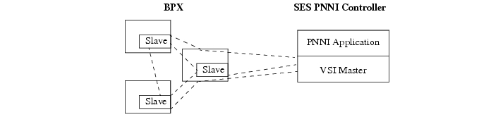
The VSI protocol is a master/slave protocol. The master part of the VSI protocol runs on the SES PNNI controller for PNNI networking, and is referred to in this application as the PNNI controller. (For MPLS, the controller is an external Tag Switch controller.) The slave part of the VSI protocol runs on the BXMs on the BPX 8620. Figure D-1 provides a simple illustration of VSI master and slave relationship.
Figure D-1 VSI, Controller and Slave VSIs

When enabled and configured, the VSI controller automatically establishes a link between the VSI master and every VSI slave on the associated switch, as shown in Figure D-2. When enabled, the VSI slaves in turn establish links between each other.
Figure D-2 VSI Master and VSI Slave Example
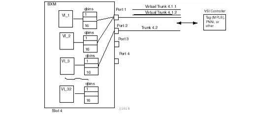
The BXM has 32 virtual interfaces that provide a number of resources including Qbin buffering capability. With physical lines and trunks, one virtual interface is assigned to each port. (Figure D-3).
With virtual trunking, a physical trunk can comprise a number of logical trunks called virtual trunks, and each of these virtual trunks is assigned the resources of one of the 32 virtual interfaces on a BXM (Figure D-3).
Each virtual interface has 16 Qbins assigned to it. Qbins 0-9 are used for AutoRoute and 10-15 are available for use by a VSI enabled on the virtual interface. (In release 9.1, only Qbin 10 was used.) The Qbins 10-15 support class of service (CoS) templates on the BPX.
A virtual switch interface may be enabled on a port, trunk, or virtual trunk. The virtual switch interface is assigned the resources of the associated virtual interface,
Figure D-3 BXM Virtual Interfaces and Qbins
Resource Partitioning
With the VSI protocol, the resources on a BXM port or trunk must be partitioned between competing controllers, AutoRoute, MPLS, and PNNI. Once the resources have been partitioned, the controller can use them for its networking application. In other words, AutoRoute uses the resources in its partition to provision permanent virtual circuits, just like a standard BPX switch. And the PNNI controller, will use the resources in its partition to establish ATM switched virtual circuits. The two partitions are completely independent and the connections from one never interfere with the connections in another partition.

Note
The resources that need to be configured for a partition are shown in Table D-1 for a partition designated ifci (interface controller 1). The three parameters that need to be distributed are number of logical connections (LCNs), bandwidth (BW), and virtual path identifiers (VPIs).
Table D-1 ifci parameters (virtual switch interface)
lcns
min_lcns
max_lcns
bw
min_bw
max_bw
vpi
min_vpi
max_vpi
Partition Criteria shows theVPI ranges available for partitions on a BXM card.
When a trunk is added, the entire bandwidth is allocated to AutoRoute. To change the allocation in order to provide resources for a VSI partition, the cnfrsrc BPX CLI command is used on the BXM.
Configuring VSI-ILMI
This section describes how to perform the following tasks for ILMI functionality:
•
•
•
Support Enabling ILMI Functionality for VSI Partitions on Port Interfaces
The ILMI protocol can either run on the BPX or on the BXM card. For ILMI functionality to work for VSI partitions, the ILMI protocol should run on the BXM card.
To enable ILMI functionality for VSI partitions on port interfaces:.
Step 1
a.
b.
Step 2
cnfvsipart 13.1 1 y
Enable ILMI Functionality for VSI Partitions on Physical Trunk Interfaces
This section describes how to enable ILMI functionality for an active VSI partition, using the example of active VSI partition 1 on a physical trunk interface 13.2.
Step 1
Step 2
Note
Enable VSI ILMI Functionality on Virtual Trunk Interfaces
This section describes how to enable ILMI functionality for an active VSI partition on a specified virtual trunk interface, using the example of active VSI partition 1 on a virtual trunk interface 13.3.1.
ILMI sessions on Virtual trunks always run on the BXM card. Hence it is not necessary that you run the cnftrk command when enabling ILMI functionality for a VSI partition on a virtual trunk interface.
Step 1
cnfvsipart 13.3.1 1 y
Note
By default LMI protocol runs on these interfaces.
Step 2
Note
The Sys_Id is generated using the NOVRAM contents in the backplane of the BPX shelf. If for some reason, this NOVRAM could not be read, then a default Sys_Id of 1 is downloaded to the BXM card. If this is done, the dspvsipartcnf command will display this information as follows:
Sys_Id generation failed!! Using default value = 0.0.0.0.0.1cnfvsipart
Use the cnfvsipart command to configure VSI partition characteristics. The cnfvsipart command is currently the only way to enable VSI ILMI sessions.
Syntax Description
cnfvsipart <slot.port.[vtrk]> <part_id> <enable_option>
Related Commands
cnfrsrc, dspvsipartcnf, cnfport, cnftrk
dspvsipartcnf
Use the dspvsipartcnf command to view VSI partition characteristics.
Currently this command only displays information about VSI ILMI sessions. This command displays whether VSI ILMI is enabled for a given partition, the LCN used for the sessions (only for trunk interfaces) and the type of IP address downloaded to the BXM card for topology discovery purposes.
On Trunk Interfaces, ILMI functionality can be enabled on one VSI partition only. Use the dspvsipartcnf command to view ILMI functionality for VSI partitions on trunk interface 13.2,
dspvsipartcnf 12.1If, for example, a VSI ILMI session is enabled on partition 1, it would provide output similar to the following example:
Trunk: 13.2 Partn: 1 ILMI: E LCN: 272 Topo: BPX NW IPTrunk: 13.2 Partn: 2 -- VSI partition DISABLEDTrunk: 13.2 Partn: 3 -- VSI partition DISABLEDSys_Id generated = 32.31.39.36.30.35The above output says that ILMI functionality is enabled on VSI partition 1 on trunk interface 13.2 and it uses LCN 272 and the BPX Network IP is exchanged by the ILMI session with the peer ILMI session.
If no partition is specified, this command displays the above information about all the VSI partitions and also the Sys_Id downloaded to the BXM card for ILMI functionality.
Syntax Description
dspvsipartcnf <slot.port.[vtrk]> [partition_id]
Class of Service Templates
Class of Service Templates (COS Templates) provide a means of mapping a set of standard connection protocol parameters to "extended" platform specific parameters. Full QoS implies that each VC is served through one of a number of Class of Service buffers (Qbins) which are differentiated by their QoS characteristics.
Note
When a connection set up request is received from the VSI Master in the PNNI or MPLS controller, the VSI slave (in the BXM) uses the class of service index of the request to retrieve the corresponding set of extended parameters defined in the template for the corresponding index. The BXM VSI slave uses these values to complete the connection setup and program the cross-connect in the card.
Functional Description
The service class template provide a means of mapping a set of extended parameters, which are generally platform specific, based on the set of standard ATM parameters passed to the VSI slave during connection setup.
A set of service templates is stored in each switch (e.g., BPX) and downloaded to the service modules (e.g., BXMs) as needed.
The service templates contains two classes of data.
•
•
The general types of parameters passed from a VSI master to a slave include:
•
•
•
•
Each VC added by a VSI master is assigned to a specific service class by means of a 32-bit service type identifier. Current identifiers are for:
•
•
•
When a connection setup request is received from a VSI master controller, the VSI slave uses the service type identifier to index into a Service Class Template database containing extended parameter settings for connections matching that index. The firmware then programs the hardware with the applicable extended parameter values to complete the connection setup.
One of the parameters specified for each service type is the particular BXM class of service buffer (Qbin) to use. The Qbin buffers provide separation of service type to match the QoS requirements.
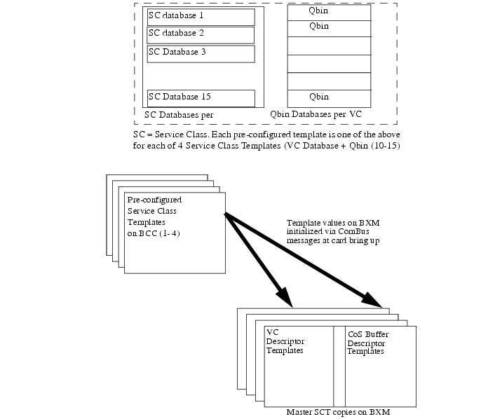
Service class templates on the BPX are maintained by the BCC and are downloaded to the BXM cards as part of the card configuration process as a result of card activation, rebuild, or switchover. In release 9.2 the templates are non-configurable.
Nine template types are available (as of 9.2.3x). You can assign any one of the templates to a virtual switch interface (Figure D-4). For more information about these templates, see the BPX documentation associated with Release 9.2.30.
Figure D-4 Service Class Template Overview
Service Class Template Structure
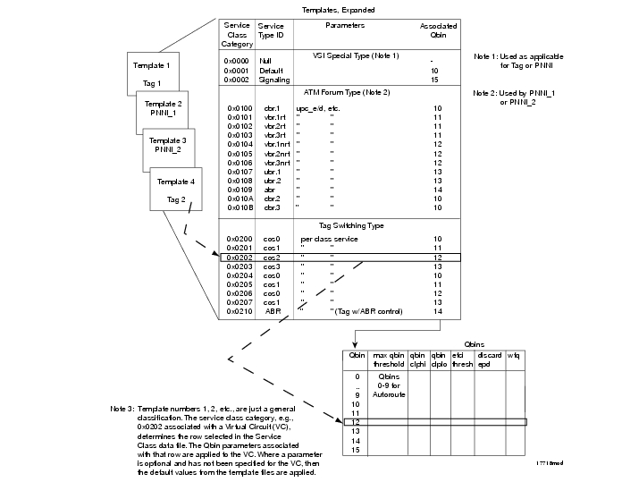
Each template table row includes an entry that defines the Qbin to be used for that class of service (Figure D-5).
This mapping defines a relationship between the template and the interface Qbin's configuration.
A Qbin template defines a default configuration for the set of Qbins for the logical interface. When a template assignment is made to an interface, the corresponding default Qbin configuration becomes the interface's Qbin configuration. Some of the parameters of the interface's Qbin configuration can be changed on a per interface basis. Such changes affect only that interface's Qbin configuration and no others, and do not affect the Qbin templates.
Qbin templates only are used with Qbins that are available to VSI partitions (PNNI or MPLS), namely Qbins 10 through 15. Qbins 10 through 15 are used by the VSI on interfaces configured as trunks or ports. The rest of the Qbins (0-9) are reserved for and configured by AutoRoute.
Figure D-5 Service Class Template and Associated Qbin Selection
Downloading Service Class Templates
Service Class Templates are downloaded to a BXM card under the following conditions:
•
•
•
•
Assignment of a Service Class Template to an interface
A default Service Class Template is assigned to a logical interface (VI) when the interface is upped via upport/uptrk.
For example:
•
•
•
This default template has the identifier of 1. Users can change the Service Class Template from Service Class Template 1 to another Service Class Template using the cnfvsiif (configure VSI interface) command. The dspvsiif command allows the user to display the template associated with the interface. For example:
•
•
•
•
cnfvsiif example
The cnfvsiif command is used to assign a selected Service Class Template to an interface (VI) by specifying the template number. It has the following syntax:
cnfvsiif <slot.port.vtrk> <tmplt_id>
dspvsiif example
The dspvsiif command is used to display the type of Service Class Template assigned to an interface (VI). It has the following syntax:
dspvsiif <slot.port.vtrk>
Card Qbin Configuration
When an interface (VI) is activated by uptrk or upport, the default Service Class Template is assigned to the interface (VI). The corresponding Qbin template is then copied into the card's (BXM) data structure of that interface. A user can change some of the Qbin parameters using the cnfqbin command. The Qbin is now "user configured" as opposed to "template configured". This information may be viewed on the dspqbin screen.
Qbin Dependencies
The available Qbin parameters are shown in Table D-3. Notice that the Qbins available for VSI are restricted to Qbins 10-15 for that interface. All 32 possible virtual interfaces are provided with 16 Qbins.
Additional Service Class Template commands are:
Extended Services Types Support
The service-type parameter for a connection is specified in the connection bandwidth information parameter group. The service-type and service-category parameters determine the service class to be used from the Service Class Template.
Connection Admission Control (CAC)
For Release 9.2, when a connection request is received by the VSI Slave, it is first subjected to a Connection Admission Control process before being forwarded to the FW layer responsible for actually programming the connection. The granting of the connection is based on the following criteria:
•
•
•
QoS guarantees
•
•
•
When the VSI slave accepts (for example, after CAC) a connection setup command from the VSI master in the PNNI or MPLS Controller, it receives information about the connection including service type, bandwidth parameters, and QoS parameters. This information is used to determine an index into the VI's selected Service Class Template's VC Descriptor table thereby establishing access to the associated extended parameter set stored in the table.
Supported Service Types
The service type identifier is a 32-bit number. Table D-4 lists the supported service types.
A summary of the parameters associated with each of the Service Class Templates is provided in Table D-5 through Table D-8. Table D-9 provides a description of these parameters and also the range of values that may be configured if the template does not assign an arbitrary value.
Table D-5 lists the parameters associated with Default (0x0001) and Signaling (0x0002) Service Class Template categories.
Table D-6 and Table D-7 lists the parameters associated with the PNNI Service Class Templates.
* indicates not applicable
Table D-8 lists the connection parameters and their default values for MPLS (Tag Switching) Service Class Templates.
Table D-9 describes the connection parameters that are listed in the preceding tables and also lists the range of values that may be configured, if not pre-configured.
 Feedback
Contact Cisco
- Open a Support Case

- (Requires a Cisco Service Contract)
This Document Applies to These Products
- Collaboration Endpoints - Retired Products
- Conferencing - Retired Products
- Contact Center - Retired Products
- Optical Networking - Retired Products
- Routers - Retired Products
- Security - Retired Products
- Servers - Unified Computing (UCS) Retired Products
- Storage Networking Retired Products
- Switches - Retired Products
- Video - Retired Products
- Wireless - Retired Products