Setting Up Connections Between Other Devices and the RPM
Available Languages
Table Of Contents
Setting Up Connections Between Other Devices and the RPM
Configuring Connections Between the RPM and Other Devices
Setting Up the RPM Connection to the PXM
Setting Up Connections Between CWM and the RPM
Setting Up Connections Between Service Modules and the RPM
FRSM Frame Aggregation: Port Forwarding
Setting Up the FRSM Connections to the PXM
FRSM-PXM Configuration Example
Setting Up the AUSM Connection to the PXM
AUSM-PXM Configuration Example
Example of PVCs with AAL5 and LLC/SNAP Encapsulation
Example of PVCs in a Fully Meshed Network
Fully Meshed ATM Configuration Example
RPM-to-Service Module DAX Connections
RPM-to-FRSM-8T1 ATM/Frame Relay SIW DAX Connection
Configuring the FRSM Interface
Configuring the Router Interface
Building the RPM Slave Connection
Building the FRSM-8T1 Master Connection
RPM-to-AUSM-8T1 IMA DAX Connection
Configuring the AUSM Interface
Configuring the Router Interface
Building the RPM-to-AUSM-IMA Slave Connection
Building the AUSM-IMA-to-AUSM-IMA Trunk Connection
RPM-to-FRSM-2CT3 ATM/PPP DAX Connection
Configuring the FRSM-2CT3 Interface
Configuring the Router Interface
Building the FRSM-2CT3 Slave Connection
RPM-to-AUSM-8T1 ATM-IMA DAX Connection
Configuring the AUSM Interface
Configuring the Cisco 7200 Router Interface
Building the AUSM Slave Connection
RPM-to-AUSM-8T1/B ATM/ATM DAX Connection
Configuring the AUSM Interface
Configuring the Router Interface
Building the AUSM Slave Connection
Building the RPM Master Connection
RPM-to-PXM Feeder Trunk Connections
RPM-to-RPM Three-Segment Connection
Configuring the RPM Interfaces
Adding the RPM-to-Trunk Connections
Adding the Trunk-to-Trunk Connection
RPM-to-FRSM-2E3 Three-Segment Connection
Configuring the FRSM-2E3 Interface
Configuring the Router Interface
Building the FRSM-2E3-to-Trunk Connection
Building the RPM-to-Trunk Connection
Building the Trunk-to-Trunk Connection
Manually Resynchronizing Connections
Automatically Resynchronizing Connections
Connection State Resynchronization
Setting Up Connections Between Other Devices and the RPM
This chapter describes how to make connections between an RPM and a PXM and among either service modules or other RPMs. The chapter contains the following sections:
•
Configuring Connections Between the RPM and Other Devices
•
•
•
•
•
Configuring Connections Between the RPM and Other Devices
After configuring port adapters on the RPM, the user's next step is to configure connections between the RPM and other devices (service modules, other RPMs) via the PXM.
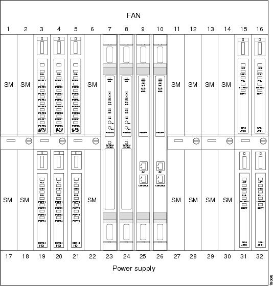
The PXM (the main processor on the MGX 8850) coordinates all communication between the RPM and service modules and other RPMs. See Figure 6-1 for a view of how service modules fit in the MGX 8850.
Figure 6-1 Service Modules in the MGX 8850
A complete connection between the RPM and any of these devices includes two parts:
•
•
Setting Up the RPM Connection to the PXM
First, set up the connection between the RPM and the PXM.
For the RPM in slot 9 connecting to slot 6, perform the following procedure:
Step 1
RPM-3(config)# int sw 5/1.1 point-to-pointip address 1.0.0.1 255.0.0.0Step 2
RPM-3(config-if)# atm pvc 2 0 1 aal5snapStep 3
RPM-3(config-if)# exitRPM-3(config)#Step 4
RPM-3(config)# rpmrscprtn PAR 100 100 1 255 0 3840 4080Partition type [par|tag|pnni] Percent ingress [<0-100>] Percent egress [<0-100>] Minimum VPI [<0-255>] Maximum VPI [<0-255> Minimum VCI [<0-3840>] Maximum VCI [<0-3840>] Number of LCNs [<0-4080>]Step 5
RPM-3(config)# addcon vcc Switch slot/1[.sub-interface] vci [rname rname] rslot rslot
r_int r_vpi r_vci [master {local | remote}]
or
RPM-3(config)# addcon vpc Switch slot/1[.sub-interface] vpi [rname rname] rslot rslot
r_int r_vpi [master {local | remote}]
Available Parameters
The following parameters are available to set up the RPM to PXM connection.
•
•
•
•
•
•
•
•
•
•
–
Use master local for connections to the PXM or to other SMs, or when connecting to FRSM, PXM for 2- or 3-segment connections. In a local (DAX) RPM-RPM connection, one side must be master.
–
•
•
–
–
–
•
–
–
–
•
•
•
•
Example RPM-PXM Configuration
The following example displays a configuration linking the RPM to the PXM module.
popeye01.1.7.PXM.a > cc(session redirected)RPM configurationUser Access VerificationPassword: (cisco)rpm01>enaPassword: (cisco)rpm01#conf tEnter configuration commands, one per line. End with CNTL/Z.rpm01(config)#int ?ATM ATM interfaceAsync Async interfaceBVI Bridge-Group Virtual InterfaceCable CMTS interfaceDialer Dialer interfaceEthernet IEEE 802.3FastEthernet FastEthernet IEEE 802.3Group-Async Async Group interfaceLex Lex interfaceLoopback Loopback interfaceNull Null interfacePort-channel Ethernet Channel of interfacesSwitch Switch Virtual InterfaceTunnel Tunnel interfaceVirtual-Template Virtual Template interfaceVirtual-TokenRing Virtual TokenRingrpm01(config)#int sw ?<1-16> Chassis slot numberrpm01(config)#int sw 9/?<0-1> Switch interface numberrpm01(config)#int sw 9/1?. <0-1>rpm01(config)#int sw 9/1.66 ?multipoint Treat as a multipoint linkpoint-to-point Treat as a point-to-point linktag-switching Treat as a tag switching link<cr>rpm01(config)#int sw 9/1.66 pointrpm01(config-subif)#ip ?Interface IP configuration subcommands:access-group Specify access control for packetsaccounting Enable IP accounting on this interfaceaddress Set the IP address of an interfaceauthentication authentication subcommandsbandwidth-percent Set EIGRP bandwidth limitbroadcast-address Set the broadcast address of an interfacecgmp Enable/disable CGMPdirected-broadcast Enable forwarding of directed broadcastsdvmrp DVMRP interface commandshello-interval Configures IP-EIGRP hello intervalhelper-address Specify a destination address for UDP broadcastshold-time Configures IP-EIGRP hold timeigmp IGMP interface commandsirdp ICMP Router Discovery Protocolload-sharing Style of load sharingmask-reply Enable sending ICMP Mask Reply messagesmroute-cache Enable switching cache for incoming multicast packetsmtu Set IP Maximum Transmission Unitmulticast IP multicast interface commandsnat NAT interface commandsnhrp NHRP interface subcommandsrpm01(config-subif)#ip address 6.6.6.6 255.255.255.0rpm01(config-subif)#atm ?address-registration Address Registrationarp-server Configure IP ARP Serverauto-configuration ATM interface auto configurationclassic-ip-extensions Specify the type of Classic IP extensionse164 E164 Configurationesi-address 7-octet ATM ESI addressilmi-enable ILMI Configurationilmi-keepalive Keepalive polling configurationlecs-address LECS Addressmultipoint-signaling Multipoint Signalingnsap-address 20-octet ATM NSAP addresspvc Create a PVCsignaling Signaling subcommandsrpm01(config-subif)#atm pvc ?<1-4095> VCD numberrpm01(config-subif)#atm pvc 66 ?<0-255> VPI numberrpm01(config-subif)#atm pvc 66 0 ?<1-65535> VCI numberrpm01(config-subif)#atm pvc 66 0 66 ?aal5ciscoppp Cisco PPP over AAL5 Encapsulationaal5mux AAL5+MUX Encapsulationaal5nlpid AAL5+NLPID Encapsulationaal5snap AAL5+LLC/SNAP Encapsulationrpm01(config-subif)#atm pvc 66 0 66 aal5snap ?<1-155000> Peak rate(Kbps)inarp Inverse ARP enableoam OAM loopback enable<cr>rpm01(config-subif)#atm pvc 66 0 66 aal5snaprpm01(config-subif)#exitrpm01(config)#rpmrscprtn ?par Partition for PARpnni Partition for PNNItag Partition for TAGrpm01(config)#rpmrscprtn par ?<0-100> Ingress Percent Bandwidthrpm01(config)#rpmrscprtn par 100 ?<0-100> Egress Percent Bandwidthrpm01(config)#rpmrscprtn par 100 100 ?<0-255> Minimum VPI Valuerpm01(config)#rpmrscprtn par 100 100 0 ?<0-255> Maximum VPI Valuerpm01(config)#rpmrscprtn par 100 100 0 255 ?<0-3840> Minimum VCI Valuerpm01(config)#rpmrscprtn par 100 100 0 255 0 ?<0-3840> Maximum VCI Valuerpm01(config)#rpmrscprtn par 100 100 0 255 0 3840 ?<0-4080> Number of LCNsrpm01(config)#rpmrscprtn par 100 100 0 255 0 3840 4080rpm01(config)#addcon ?vcc Add a vcc connectionvpc Add a vpc connectionrpm01(config)#addcon vcc ?Switch Switch Virtual Interfacerpm01(config)#addcon vcc sw ?<1-16> Chassis slot numberrpm01(config)#addcon vcc sw 9/?<0-1> Switch interface numberrpm01(config)#addcon vcc sw 9/1?<0-1> Switch sub-interface numberrpm01(config)#addcon vcc sw 9/1.66 ?<1-3824> local VCI valuerpm01(config)#addcon vcc sw 9/1.66 66 ?rname remote node namerslot Remote slot numberrpm01(config)#addcon vcc sw 9/1.66 66 rslot ?<0-30> Remote slot numberrpm01(config)#addcon vcc sw 9/1.66 66 rslot 0 ?<0-512> Remote interfacerpm01(config)#addcon vcc sw 9/1.66 66 rslot 0 1 ?<0-255> Remote VPIrpm01(config)#addcon vcc sw 9/1.66 66 rslot 0 1 0 ?<0-65535> Remote VCIrpm01(config)#addcon vcc sw 9/1.66 66 rslot 0 1 0 66 ?cost Maximum connection costmaster Master end of the ATM connectionpriority Routing priorityrestriction Restricted Trunk Typermcr Connection Remote MCRrpcr Connection Remote PCRrutil Connection Remote percent utilizationutil Connection precent utilization<cr>rpm01(config)#addcon vcc sw 9/1.66 66 rslot 0 1 0 66 master ?local Local optionremote Remote optionrpm01(config)#addcon vcc sw 9/1.66 66 rslot 0 1 0 66 master local ?cost Maximum connection costpriority Routing priorityrestriction Restricted Trunk Typermcr Connection Remote MCRrpcr Connection Remote PCRrutil Connection Remote percent utilizationutil Connection precent utilization<cr>rpm01(config)#addcon vcc sw 9/1.66 66 rslot 0 1 0 66 master local
Note
The RPM is the MASTER and not the slave.
SlotNo = 0 (zero) which points to the active PXM.
rpm01(config)#exitrpm01#wr memBuilding configuration...rpm01#wr tBuilding configuration...Current configuration:!version 12.0no service padservice timestamps debug uptimeservice timestamps log uptimeno service password-encryption!hostname rpm01!boot system c:rpm-js-mz.120-2.5.Tenable password cisco!ip subnet-zero!!!interface FastEthernet1/1no ip addressno ip directed-broadcastshutdown!interface Ethernet2/1no ip addressno ip directed-broadcastshutdown!..!interface Ethernet2/4no ip addressno ip directed-broadcastshutdown!interface Switch9/1no ip addressno ip directed-broadcast!!interface Switch9/1.66 point-to-pointip address 6.6.6.6 255.255.255.0no ip directed-broadcastatm pvc 66 0 66 aal5snap!!ip classless!!!line con 0transport input noneline aux 0line vty 0 4password ciscologin!rpmrscprtn PAR 100 100 0 255 0 3840 4080addcon vcc switch 9/1.66 66 rslot 0 1 0 66 master localendrpm01#cc 7(session redirected)PXM configurationpopeye01.1.7.PXM.a > dspcons (connection added is shown in blue)dspconsThis End Node Name Other End Status1.1.0.0 popeye01 7.1.10.100 OK2.1.0.100 popeye01 7.1.0.100 OK3.1.20.200 popeye01 7.1.20.200 OK7.1.0.100 popeye01 2.1.0.100 OK7.1.10.100 popeye01 1.1.0.0 OK7.1.20.200 popeye01 3.1.20.200 OK7.1.0.66 popeye01 9.1.0.66 OK9.1.0.66 popeye01 7.1.0.66 OKpopeye01.1.7.PXM.a > addconaddconERR: incorrect number of parameters: (not enough)Syntax: addcon "port_no conn_type local_VPI local_VCI service [mastership][remoteConnId]"port_no -- a number 1..32conn_type -- a number 1..2 (1: vpc 2: vcc)local_VPI -- a number 0..4095local_VCI -- a number 0..65535service -- a number 1..4 (1:cbr 2:vbr 3:abr 4:ubr)mastership -- a number 1..2 (1:master 2:slave default:2)remoteConnId -- a string (format: NodeName.SlotNo.PortNo.VPI.VCI),required if mastership is 1 (master)popeye01.1.7.PXM.a > addcon 1 2 0 66 1 2 popeye01.9.1.0.66addcon 1 2 0 66 1 2 popeye01.9.1.0.66Connection ID: popeye01.0.1.0.66
Note
The PXM is NOT the master but the slave.
Setting Up Connections Between CWM and the RPM
In an MGX 8850 standalone application, you need to set up and configure connections between the Cisco WAN Manager (CWM) and the RPM in order to access and configure the PXM module through the RPM. Do this by adding a connection to the 7.34 port on the PXM.
On the RPM Side
Use the following configuration procedure on the RPM side to set up this connection.
Step 1
Step 2
Note
Step 3
Step 4
Step 5
On the PXM Side
Use the following configuration procedure on the PXM side to set up this connection.
Step 1
Step 2
Note
The connection should be in OK state.
Step 3
Step 4
Step 5
You should now be able to access the MGX 8850, MGX 8250, or MGX 8230 shelf from CWM via the RPM.
Sample CWM-PXM Configuration
Here is a sample configuration linking the CWM with the PXM through the RPM module.
On the RPM Side
The following screen capture displays how the connection looks from the RPM.
interface Switch1.1 point-to-pointip address 11.11.11.1 255.255.255.252no ip route-cacheno ip mroute-cachepvc 0/10encapsulation aal5snap!ip route 0.0.0.0 0.0.0.0 Ethernet1/1ip route 172.1.1.0 255.255.255.0 Switch1.1 <---- Important!rpmrscprtn PAR 100 100 0 255 0 3840 4080addcon auto_synch offaddcon vcc switch 1.1 10 rslot 7 34 0 34 master localShow commandsnetboot-rpm2#show switch connectionsSynch1Vpi lVci remoteNodeName remoteSlot remoteIf rVpi rVci Status0 10 7 34 0 34 inSynchnetboot-rpm2#show ip routeCodes: C - connected, S - static, I - IGRP, R - RIP, M - mobile, B - BGPD - EIGRP, EX - EIGRP external, O - OSPF, IA - OSPF inter areaN1 - OSPF NSSA external type 1, N2 - OSPF NSSA external type 2E1 - OSPF external type 1, E2 - OSPF external type 2, E - EGPi - IS-IS, L1 - IS-IS level-1, L2 - IS-IS level-2, ia - IS-ISinter area* - candidate default, U - per-user static route, o - ODRP - periodic downloaded static routeGateway of last resort is 0.0.0.0 to network 0.0.0.0172.1.0.0/24 is subnetted, 1 subnetsS 172.1.1.0 is directly connected, Switch1.1172.29.0.0/24 is subnetted, 1 subnetsC 172.29.37.0 is directly connected, Ethernet1/110.0.0.0/8 is variably subnetted, 2 subnets, 2 masksS 10.10.10.2/32 is directly connected, Switch1.1C 10.10.10.0/24 is directly connected, Loopback011.0.0.0/30 is subnetted, 1 subnetsC 11.11.11.0 is directly connected, Switch1.1S* 0.0.0.0/0 is directly connected, Ethernet1/1netboot-rpm2#Verification of PXM ATM/ip address access from RPMnetboot-rpm2#ping 172.1.1.201Type escape sequence to abort.Sending 5, 100-byte ICMP Echos to 172.1.1.201, timeout is 2 seconds:!!!!!Success rate is 100 percent (5/5), round-trip min/avg/max = 1/2/4 msnetboot-rpm2#On the PXM Side
The following screen capture displays how the connection looks from the PXM.
mgx2.1.7.PXM.a > dspifipInterface Flag IP Address Subnetmask Broadcast Addr-------------- ---- --------------- --------------- ---------------Ethernet/lnPci0 UP 172.29.37.91 255.255.255.0 172.29.37.255SLIP/sl0 DOWN 0.0.0.0 255.0.0.0 (N/A)ATM/atm0 UP 172.1.1.201 255.255.255.0 172.1.1.255mgx2.1.7.PXM.a > dspconsThis End Node Name Other End Status2.1.0.10 mgx2 7.34.0.34 OK7.34.0.34 mgx2 2.1.0.10 OKmgx2.1.7.PXM.a > dspcon 2.1.0.10Conn Par Addr : 2.1.0.10Vc Index : 805306369Conn SM Addr : Ept: vpi = 0 vci = 10 vpc = 0ifNum = 0x20001 conNum = 0x7fff glcn = 0x2c1 lcn = 26qosFwd = 263 qosBwd = 263 pcrFwd = 353208 pcrBwd = 353208 mcrFwd =0 mcrBwd= 0Remote Node Name : mgx2Remote Conn PAR Addr: 7.34.0.34Remote Conn SM Addr: Ept: vpi = 0 vci = 34 vpc = 0ifNum = 0x70022 conNum = 0x7fff glcn = 0x2c0 lcn = 0qosFwd = 263 qosBwd = 263 pcrFwd = 353208 pcrBwd = 353208 mcrFwd =0 mcrBwd= 0OE VC Index : 805306369Oper Status : OKConn Failure Reason :RRT Failure Reason :Admin Status : UPRoute :Setting Up Connections Between Service Modules and the RPM
To complete a RPM-to-service module connection, configure the connection between the service module and the PXM.
Types of Service Modules
Service modules can be of various types, including FRSM (Frame Relay Service Module), AUSM (ATM UNI Service Module), and VISM (Voice Interworking Service Module).
•
•
•
•
Data Forwarding to RPMs
Service modules can be configured to forward data to the RPMs in one of two modes: port forwarding or connection forwarding.
FRSM Frame Aggregation: Port Forwarding
In this mode, all frames received on a port are forwarded to the router for L3 processing. For example, a FRSM T1 could be configured for PPP IP access, by doing the following.
1.
2.
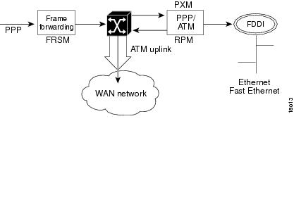
The data flow for a PPP connection destined for the RPM is shown in the figure below. The packet enters the FRSM module as PPP and is frame forwarded to the RPM. The RPM receives the packet in PPP over ATM because MGX 8850 internal connectivity is ATM. The RPM runs software that works with PPP over ATM encapsulation, allowing the router to reach the IP layer and route the packet to its destination (such as the Internet). Packets then destined to the Internet via a WAN network are then sent back to the PXM, and out the ATM uplink.
Figure 6-2 Internal Path of a PPP Packet Destined for RPM
PPP over ATM Example
In this PPP over ATM example, the FRSM is in slot 18 and RPM A is in slot 12. A serial port on Router B is connected to the FRSM line 1.
***Router B (connected to line 1 of FRSM) configuration example:
interface Serial5/0ip address 192.168.100.2 255.255.255.0encapsulation ppp***The following is an example of a FRSM configuration. (See FRSM documentation for complete command syntax.)
Step 1
SQureshi.1.18.FRSM.a> addln 1Step 2
SQureshi.1.18.FRSM.a> addport 1 1 2 1 24 3Step 3
Step 4
SQureshi.1.18.FRSM.a> addcon 1 1000 1536000 5 2 1 2 SQureshi.12.1.0.1001***RPM configuration example:
interface Virtual-Template12/1ip address 192.168.100.12 255.255.255.0!interface Switch12/1.100 point-to-pointatm pvc 100 0 1001 aal5ciscoppp Virtual-Template12/1!rpmrscprtn par 100 100 0 255 0 3840 4080addcon vcc Switch 12/1.100 1001 rslot 18 1 0 1000 master local***
The following example displays how to verify connectivity.
RPM A--rpm_slot12# show atm vc 100Switch12/1.100:VCD:100, VPI:0, VCI:1001UBR, PeakRate:149760AAL5-CISCOPPP, etype:0x9, Flags:0xC2A, VCmode:0x0OAM frequency:0 second(s)InARP DISABLEDTransmit priority 4InPkts:57, OutPkts:90, InBytes:1828, OutBytes:2068InPRoc:57, OutPRoc:90InFast:0, OutFast:0, InAS:0, OutAS:0InPktDrops:0, OutPktDrops:0CrcErrors:0, SarTimeOuts:0, OverSizedSDUs:0OAM cells received:0OAM cells sent:0Status:UPPPP:Virtual-Access12/1 from Virtual-Template12/1rpm_slot12#show interface Virtual-Template12/1Virtual-Access12/1 is up, line protocol is upHardware is Virtual Access interfaceInternet address is 192.168.100.12/24MTU 1500 bytes, BW 100000 Kbit, DLY 100000 usec,reliablility 255/255, txload 1/255, rxload 1/255Encapsulation PPP, loopback not setKeepalive set (10 sec)DTR is pulsed for 5 seconds on resetLCP OpenOpen:IPCPBound to Switch12/1.100 VCD:100, VPI:0, VCI:1001Cloned from virtual-template:1Last input 00:00:07, output never, output hang neverLast clearing of "show interface" counters 00:06:17Queueing strategy:fifoOutput queue 0/40, 0 drops; input queue 0/75, 0 drops5 minute input rate 0 bits/sec, 0 packets/sec5 minute output rate 0 bits/sec, 0 packets/sec59 packets input, 1632 bytes, 0 no bufferReceived 59 broadcasts, 0 runts, 0 giants, 0 throttles0 input errors, 0 CRC, 0 frame, 0 overrun, 0 ignored, 0 abort92 packets output, 2100 bytes, 0 underruns0 output errors, 0 collisions, 0 interface resets0 output buffer failures, 0 output buffers swapped out0 carrier transitionsrpm_slot12#ping 192.168.100.2Type escape sequence to abort.Sending 5, 100-byte ICMP Echos to 192.168.100.2, timeout is 2 seconds:!!!!!Success rate is 100 percent (5/5), round-trip min/avg/max = 4/4/8 msrpm_slot12#sh ip ro...192.168.100.0/24 is variably subnetted, 2 subnets, 2 masksC 192.168.100.0/24 is directly connected, Virtual-Access12/1C 192.168.100.2/32 is directly connected, Virtual-Access12/1Router B --router_B#sh int s5/0Serial5/0 is up, line protocol is upHardware is M4TInternet address is 192.168.100.2/24MTU 1500 bytes, BW 1544 Kbit, DLY 20000 usec,reliablility 255/255, txload 1/255, rxload 1/255Encapsulation PPP, crc 16, loopback not set, keepalive set (10 sec)LCP OpenListen:CDPCPOpen:IPCPLast input 00:00:00, output 00:00:00, output hang neverLast clearing of "show interface" counters neverInput queue:0/75/0 (size/max/drops); Total output drops:0Queueing strategy:weighted fairOutput queue:0/1000/64/0 (size/max total/threshold/drops)Conversations 0/1/256 (active/max active/max total)Reserved Conversations 0/0 (allocated/max allocated)5 minute input rate 0 bits/sec, 0 packets/sec5 minute output rate 0 bits/sec, 0 packets/sec35953 packets input, 529169 bytes, 0 no bufferReceived 35639 broadcasts, 0 runts, 1 giants, 0 throttles211 input errors, 176 CRC, 0 frame, 0 overrun, 0 ignored, 35 abort36172 packets output, 487073 bytes, 0 underruns0 output errors, 0 collisions, 2465 interface resets0 output buffer failures, 0 output buffers swapped out2475 carrier transitions DCD=up DSR=up DTR=up RTS=up CTS=uprouter_B#sh ip ro...192.168.100.0/24 is variably subnetted, 2 subnets, 2 masksC 192.168.100.12/32 is directly connected, Serial5/0C 192.168.100.0/24 is directly connected, Serial5/0router_B#ping 192.168.100.12Type escape sequence to abort.Sending 5, 100-byte ICMP Echos to 192.168.100.12, timeout is 2 seconds:!!!!!Success rate is 100 percent (5/5), round-trip min/avg/max = 4/5/8 msFRSM --SQureshi.1.18.FRSM.a > dsplnsLine Conn Type Status/Coding Length XmtClock Alarm StatsType Source Alarm---- ----- ------------ ------ -------- ------------- -------- ----- -----18.1 RJ-48 dsx1ESF Ena/dsx1B8ZS 0-131 ft LocalTim No No18.2 RJ-48 dsx1ESF Dis/dsx1B8ZS 0-131 ft LocalTim18.3 RJ-48 dsx1ESF Dis/dsx1B8ZS 0-131 ft LocalTim18.4 RJ-48 dsx1ESF Dis/dsx1B8ZS 0-131 ft LocalTim18.5 RJ-48 dsx1ESF Dis/dsx1B8ZS 0-131 ft LocalTim18.6 RJ-48 dsx1ESF Dis/dsx1B8ZS 0-131 ft LocalTim18.7 RJ-48 dsx1ESF Dis/dsx1B8ZS 0-131 ft LocalTim18.8 RJ-48 dsx1ESF Dis/dsx1B8ZS 0-131 ft LocalTimLineNumOfValidEntries:8Syntax :dsplnsSQureshi.1.18.FRSM.a > dspportsPort Ena/Speed EQServ SignalType T391 T392 N391 N392 N393 Type Alarm ELMIRatio-------- --- ----- ------ ------------ ---- ---- ---- ---- ---- -------- ----- ----18.1.1 Add/1536k 1 NoSignaling 10 15 6 3 4 frForwar No OffNumber of ports: 1PortDs0UsedLine1: 0x00ffffffPortDs0UsedLine2: 0x00000000PortDs0UsedLine3: 0x00000000PortDs0UsedLine4: 0x00000000PortDs0UsedLine5: 0x00000000PortDs0UsedLine6: 0x00000000PortDs0UsedLine7: 0x00000000PortDs0UsedLine8: 0x00000000PortNumNextAvailable: 119Syntax :dspportsSQureshi.1.18.FRSM.a > dspchansDLCI Chan EQ I/EQDepth I/EQDEThre I/EECNThre Fst/ DE Type Alarm------------- ---- -- ----- ----- ----- ----- ----- ----- --- --- ----- -----18.1.1.1000 101 2 65535/65535 32767/32767 6553/6553 Dis/Dis frFor NoNumber of channels: 1ChanNumNextAvailable: 30Syntax :dspchans*****Connection Forwarding
In this mode, all frames received on a given connection are forwarded to the router using the appropriate ATM encapsulation. For example, Frame Relay connections on a FRSM port could be forwarded to the RPM by
•
•
•
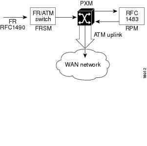
The data flow for a native Frame Relay connection destined to the RPM is shown in Figure 6-3. This data flow is identical to that of PPP packets, but the encapsulation techniques are different. Standard Frame Relay is encapsulated using RFC1490. When a packet is received at the FRSM that has been encapsulated using RFC1490, the standard FR-ATM service interworking translation mode (FRF.8) is performed so that when the packet is forwarded to the RPM it is encapsulated using RFC1483. The router also reads RFC1483, enabling it to reach the IP layer, and route the packet.
Figure 6-3 Path of a Native Frame Relay Connection
Frame over ATM Example
In this example, the FRSM-8T1 is in slot 18 of the MGX 8850, while the RPM is in slot 12.
A Frame Relay router (connected to line 1 of FRSM) configuration example follows:
interface Serial0ip address 192.168.101.2 255.255.255.0encapsulation frame-relay IETF***The following is an example of a FRSM configuration. (See FRSM documentation for complete command syntax.)
Step 1
SQureshi.1.18.FRSM.a> addln 1Step 2
SQureshi.1.18.FRSM.a> addport 1 1 2 1 24 1SQureshi.1.18.FRSM.a> xcnfport -pt 1 -sig 3Step 3
SQureshi.1.18.FRSM.a> addcon 1 212 1536000 3 2 1 2 SQureshi.12.1.0.101***RPM configuration example:
interface Switch12/1.101 multipointip address 192.168.101.12 255.255.255.0atm pvc 101 0 101 aal5snap inarp!rpmrscprtn par 100 100 0 255 0 3840 4080addcon vcc Switch 12/1.101 101 rslot 18 1 0 212 master local***To verify connectivity:
RPM --rpm_slot12#ping 192.168.101.2Type escape sequence to abort.Sending 5, 100-byte ICMP Echos to 192.168.101.2, timeout is 2 seconds:!!!!!Success rate is 100 percent (5/5), round-trip min/avg/max = 4/5/8 msrpm_slot12#sh arpProtocol Address Age (min) Hardware Addr Type InterfaceInternet 192.168.101.2 0 0 / 101 ATM Switch12/1.101rpm_slot12#Frame Relay router --rpm7206_2#show frame-relay mapSerial5/0 (up):ip 192.168.101.12 dlci 212(0xD4,0x3440), dynamic,broadcast,IETF, BW = 1536000, status defined, activerpm7206_2#ping 192.168.101.12Type escape sequence to abort.Sending 5, 100-byte ICMP Echos to 192.168.101.12, timeout is 2 seconds:!!!!!Success rate is 100 percent (5/5), round-trip min/avg/max = 4/4/8 msrpm7206_2#FRSM --SQureshi.1.18.FRSM.a > dspchansDLCI Chan EQ I/EQDepth I/EQDEThre I/EECNThre Fst/ DE Type Alarm------------- ---- -- ----- ----- ----- ----- ----- ----- --- --- ----- -----18.1.1.212 121 2 65535/65535 32767/32767 6553/6553 Dis/Dis SIW-X NoNumber of channels: 1ChanNumNextAvailable: 26Syntax :dspchansSQureshi.1.18.FRSM.a > dspportsPort Ena/Speed EQServ SignalType T391 T392 N391 N392 N393 Type Alarm ELMIRatio-------- --- ----- ------ ------------ ---- ---- ---- ---- ---- -------- ----- ----18.1.1 Add/1536k 1 StrataLMI 10 15 6 3 4 frameRel No OffNumber of ports: 1PortDs0UsedLine1: 0x00ffffffPortDs0UsedLine2: 0x00000000PortDs0UsedLine3: 0x00000000PortDs0UsedLine4: 0x00000000PortDs0UsedLine5: 0x00000000PortDs0UsedLine6: 0x00000000PortDs0UsedLine7: 0x00000000PortDs0UsedLine8: 0x00000000PortNumNextAvailable: 83Syntax :dspportsSQureshi.1.18.FRSM.a > dsplnsLine Conn Type Status/Coding Length XmtClock Alarm StatsType Source Alarm---- ----- ------------ ------ -------- ------------- -------- ----- -----18.1 RJ-48 dsx1ESF Ena/dsx1B8ZS 0-131 ft LocalTim No No18.2 RJ-48 dsx1ESF Dis/dsx1B8ZS 0-131 ft LocalTim18.3 RJ-48 dsx1ESF Dis/dsx1B8ZS 0-131 ft LocalTim18.4 RJ-48 dsx1ESF Dis/dsx1B8ZS 0-131 ft LocalTim18.5 RJ-48 dsx1ESF Dis/dsx1B8ZS 0-131 ft LocalTim18.6 RJ-48 dsx1ESF Dis/dsx1B8ZS 0-131 ft LocalTim18.7 RJ-48 dsx1ESF Dis/dsx1B8ZS 0-131 ft LocalTim18.8 RJ-48 dsx1ESF Dis/dsx1B8ZS 0-131 ft LocalTimLineNumOfValidEntries:8Syntax :dsplnsSQureshi.1.18.FRSM.a >
ATM Service
The ATM UNI Service Modules (AUSMs) provide native ATM UNI (compliant with ATM Forum v3.0 and v3.1) interfaces at T1 and E1 speeds, with eight ports per card, providing up to16 Mbps of bandwidth for ATM service interfaces. This is compliant with the physical and ATM layer, but not with signaling.
Consistent with Cisco Intelligent QoS Management features, AUSM cards support per-VC queuing on ingress and multiple class-of-service queues on egress. AUSM cards fully support continuous bit rate (CBR), variable bit rate (VBR), unspecified bit rate (UBR), and available bit rate (ABR) service classes.
The AUSM-8 cards also support ATM Forum-compliant inverse multiplexing for ATM (IMA). This capability enables multiple T1 or E1 lines to be grouped into a single high-speed ATM port. This
N x T1 and N x E1 capability fills the gap between T1/E1 and T3/E3, providing bandwidth up to
12 Mbps (N x T1) or 16 Mbps (N x E1) without requiring a T3/E3 circuit.A single AUSM card can provide hot standby redundancy for all active AUSM cards of the same type in the shelf (1:N redundancy).
AUSM modules are supported by standards-based management tools, including SNMP, TFTP (for configuration and statistics collection), and a command line interface. The Cisco WAN Manager application also provides full graphical user interface support for connection management, and CiscoView software provides equipment management.
Table 6-1 summarizes the key attributes of the AUSM cards.
Setting Up the FRSM Connections to the PXM
The following procedure may be used for configuring the FRSM connections to the PXM. The AUSM is slightly different and is in the section "Setting Up the AUSM Connection to the PXM," later in this chapter.
Step 1
Step 2
8250name.1.slot.FRSM.a> cc 12Step 3
8250name.1.slot.FRSM.a> dsplnsStep 4
8250name.1.slot.FRSM.a> addln 2Step 5
8250name.1.slot.FRSM.a> dspportsStep 6
8250name.1.slot.FRSM.a> addport port_num line_num port_typeStep 7
8250name.1.slot.FRSM.a> dspportsStep 8
8250name.1.slot.FRSM.a> xcnfport "-pt" (PortNum) -sig (type)"<cr>Step 9
8250name.1.slot.FRSM.a> addcon "port dlci cir chan_type [CAC]
[Controller_Type][mastership][remoteConnId]"
The parameters are
•
•
•
•
–
–
–
–
–
•
•
•
•
–
–
–
Where controller ID can be 1(PAR), 2(PNNI), 3(TAG)
FRSM-PXM Configuration Example
The following example displays a FRSM-PXM configuration.
popeye01.1.2.FRSM.a > dspcdModuleSlotNumber: 2FunctionModuleState: ActiveFunctionModuleType: FRSM-8T1FunctionModuleSerialNum: 788039FunctionModuleHWRev: abFunctionModuleFWRev: 5.0.00_04Feb99_2_CIRFunctionModuleResetReason: Reset by ASC from Cell BusLineModuleType: LM-RJ48-8T1LineModuleState: PresentmibVersionNumber: 20configChangeTypeBitMap: CardCnfChng, LineCnfChngcardIntegratedAlarm: Clearfab number: 28-2069-02popeye01.1.2.FRSM.a >popeye01.1.2.FRSM.a > addlnERR : incorrect number of parameters (not enough)Syntax : addln "line_num"line number -- values ranging from 1-8 are accepted, for FRSM_8possible errors are :a) illegal/invalid parametersb) line aleady existspopeye01.1.2.FRSM.a > addln 1popeye01.1.2.FRSM.a > cnflnERR : incorrect number of parameters (not enough)Syntax : cnfln "line_num line_code line_len clk_src [E1-signaling]"line number -- values ranging from 1-8 are accepted, for FRSM_8line code -- 2 for B8ZS (T1),3 for HDB3 (E1),4 for AMI (T1/E1)line length -- 10-15 for T1,8 for E1 with SMB line module,9 for E1 with RJ48 line moduleclock source -- clock source : 1 for loop clock, 2 for local clockE1 signaling -- CAS: CAS, no CRC; CAS_CRC: CAS, with CRC;CCS: CCS, no CRC; CCS_CRC: CCS, with CRCCLEAR : Clear E1possible errors are :a) illegal/invalid parametersb) line doesn't exist, use addln to add line firstc) loopback/bert is onpopeye01.1.2.FRSM.a > cnfln 1 2 10 2popeye01.1.2.FRSM.a > dsplnsLine Conn Type Status/Coding Length XmtClock Alarm StatsType Source Alarm---- ----- ------------ ------ -------- ------------- -------- ----- -----2.1 RJ-48 dsx1ESF Mod/dsx1B8ZS 0-131 ft LocalTim No No2.2 RJ-48 dsx1ESF Dis/dsx1B8ZS 0-131 ft LocalTim2.3 RJ-48 dsx1ESF Dis/dsx1B8ZS 0-131 ft LocalTim2.4 RJ-48 dsx1ESF Dis/dsx1B8ZS 0-131 ft LocalTim2.5 RJ-48 dsx1ESF Dis/dsx1B8ZS 0-131 ft LocalTim2.6 RJ-48 dsx1ESF Dis/dsx1B8ZS 0-131 ft LocalTim2.7 RJ-48 dsx1ESF Dis/dsx1B8ZS 0-131 ft LocalTim2.8 RJ-48 dsx1ESF Dis/dsx1B8ZS 0-131 ft LocalTimLineNumOfValidEntries: 8Syntax : dsplnspopeye01.1.2.FRSM.a > addportERR : incorrect number of parameters (not enough)Syntax : addport "port_num line_num ds0_speed begin_slot num_slot port_type"port number -- values ranging from 1-192 are accepted for T1 and 1-248for E1line number -- value ranging from 1 to 8DS0 speed -- 1 for 56K, 2 for 64Kbeginning slot -- beginning time slot in 1 basenumber of slot -- number of DS0 time slots assigned toport type -- values 1-3, 1=frame relay, 2=FUNI mode-1a, 3=frForwardpossible errors are :a) illegal/invalid parametersb) port already existsc) line not enabledd) line not channelizedpopeye01.1.2.FRSM.a > addport 1 1 2 1 2 1popeye01.1.2.FRSM.a > upportERR : incorrect number of parameters (not enough)Syntax : upport "port_num "port number -- values ranging from 1-192 are accepted for T1 and 1-248for E1possible errors are :a) illegal/invalid parameter for port numbersprint01.1.2.FRSM.a > upport 1popeye01.1.2.FRSM.a > dspportsPort Ena/Speed EQServ SignalType T391 T392 N391 N392 N393 Type Alarm ELMIRatio-------- --- ----- ------ ------------ ---- ---- ---- ---- ---- -------- ----- ----2.1.1 Mod/ 128k 1 NoSignaling 10 15 6 3 4 frameRel No OffNumber of ports: 1PortDs0UsedLine1: 0x00000003PortDs0UsedLine2: 0x00000000PortDs0UsedLine3: 0x00000000PortDs0UsedLine4: 0x00000000PortDs0UsedLine5: 0x00000000PortDs0UsedLine6: 0x00000000PortDs0UsedLine7: 0x00000000PortDs0UsedLine8: 0x00000000PortNumNextAvailable: 19Syntax : dspportspopeye01.1.2.FRSM.a > addconERR : incorrect number of parameters (not enough)Syntax : addcon "port dlci cir chan_type [CAC][Controller_Type][mastership][remoteConnId]"port number -- values ranging from 1-192 are accepted for T1 and 1-248for E1DLCI number -- value ranging from 0 to 1023committed rate -- 0-1536000 bps for T1; 0-2048000 bps for E1chan type -- values 1-5, 1=NIW 2=SIW-transparent 3=SIW-xlation 4=FUNI 5=frForwardCAC -- Connection Admission Control (optional); 1 = enable, 2 = disable(default)Controller Type (Signaling) -- 1: PVC (PAR) - Default , 2: SPVC (PNNI)mastership -- 1 for master, 2 for slaveRemote end Connection ID -- Format :NodeName.SlotNo.PortNo.Dlci ORNodeName.SlotNo.PortNo.ControllerId.Dlci for FR end point ORNodeName.SlotNo.PortNo.VPI.VCI for ATM end point.Where controller ID can be 1(PAR),2(PNNI),3(TAG)possible errors are :a) Illegal/Invalid parametersb) channel already existsc) port may not be uppopeye01.1.2.FRSM.a > addcon 1 100 128000 2 2 1 2 popeye01.0.1.0.100
Note
Setting Up the AUSM Connection to the PXM
Use the following procedure to establish an ATM UNI/NNI connection using the AUSM card. The connection is between a T1 or E1 ATM UNI on the AUSM card and an ATM service interface elsewhere in the IPX/BPX network.
Step 1
Step 2
RPM-3 (configure)# addln <line # (between 1 and 8)>Step 3
Step 4
Step 5
The parameters are
•
•
•
0 = disable queue
1 = high priority, always serve
2 = best available
3 = Min. guaranteed bandwidth
4 = Min. guaranteed bandwidth with max. rate shaping
5 = CBR with smoothing•
•
•
•
•
Step 6
The parameters are
•
•
•
•
•
•
•
Step 7
cnfupc cbr
cnfupc vbr
cnfupc abrStep 8
Step 9
Step 10
AUSM-PXM Configuration Example
The following example displays an AUSM to PXM configuration.
AUSM configurationpopeye01.1.3.AUSMB8.a > dspcdModuleSlotNumber: 3FunctionModuleState: ActiveFunctionModuleType: AUSMB-8T1FunctionModuleSerialNum: 023113FunctionModuleHWRev: aaFunctionModuleFWRev: 10.0.00_12Feb99_1FunctionModuleResetReason: Reset by ASC from Cell BusLineModuleType: LM-RJ48-8T1LineModuleState: PresentmibVersionNumber: 20configChangeTypeBitMap: CardCnfChng, LineCnfChngcardIntegratedAlarm: MajorcardMajorAlarmBitMap: Line AlarmcardMinorAlarmBitMap: Channel failurefab number: 28-2580-01popeye01.1.3.AUSMB8.a > addlnERR : incorrect number of parameters (not enough)Syntax : addln "line_num"line number -- values ranging from 1-8 are accepted, for AUSM-8T1/8E1,IMATM-T3T1/E3E1possible errors are :a) illegal/invalid parametersb) line aleady existspopeye01.1.3.AUSMB8.a > addln 1popeye01.1.3.AUSMB8.a > cnfln 1ERR : incorrect number of parameters (not enough)Syntax : cnfln "line_num line_code line_len clk_src [E1-signaling]"line number -- values ranging from 1-8 are accepted, for AUSM-8T1/8E1,IMATM-T3T1/E3E1line code -- 2 for B8ZS (T1),3 for HDB3 (E1)line length -- 10-15 for T1, 8 for E1 with SMB module,9 for E1 with RJ48 line moduleclock source -- clock source : 1 for loop clock, 2 for local clockE1 signaling -- CCS: CCS, no CRC; CCS_CRC: CCS, with CRC;CLEAR: Clear E1possible errors are :a) illegal/invalid parametersb) line doesn't exist, use addln to add line firstc) loopback/bert is onpopeye01.1.3.AUSMB8.a > cnfln 1 2 10 2popeye01.1.3.AUSMB8.a > dsplnsLine Conn Type Status/Coding Length XmtClock Alarm StatsType Source Alarm---- ----- ------------ ------ -------- ------------- -------- ----- -----3.1 RJ-48 dsx1ESF Mod/dsx1B8ZS 0-131 ft LocalTim Yes No3.2 RJ-48 dsx1ESF Dis/dsx1B8ZS 0-131 ft LocalTim3.3 RJ-48 dsx1ESF Dis/dsx1B8ZS 0-131 ft LocalTim3.4 RJ-48 dsx1ESF Dis/dsx1B8ZS 0-131 ft LocalTim3.5 RJ-48 dsx1ESF Dis/dsx1B8ZS 0-131 ft LocalTim3.6 RJ-48 dsx1ESF Dis/dsx1B8ZS 0-131 ft LocalTim3.7 RJ-48 dsx1ESF Dis/dsx1B8ZS 0-131 ft LocalTim3.8 RJ-48 dsx1ESF Dis/dsx1B8ZS 0-131 ft LocalTimLineNumOfValidEntries: 8Syntax : dsplnspopeye01.1.3.AUSMB8.a > addportERR : incorrect number of parameters (not enough)Syntax : addport "port_num port_type line_num"port number -- values ranging from 1-8Port Type -- 1 - UNI, 2 - NNIline number -- value ranging from 1 to 8possible errors are :a) Incorrect parametersb) Line not presentc) Line part of another IMA port or ATM portd) Port already in usepopeye01.1.3.AUSMB8.a > addport 1 1 1popeye01.1.3.AUSMB8.a > dspportsList of ATM ports:==================Port PortType Line# Portenable Speed PortState---- -------- ----- ---------- ----- ---------3.1 UNI 1 UP 3622 ActiveNo IMA ports are currently activeSyntax : dspportspopeye01.1.3.AUSMB8.a > addconERR : incorrect number of parameters (not enough)Syntax : addcon "port_num vpi vci conn_type service_type [Controller_Type] [mastership] [remoteConnId]"port number -- values ranging from 1-8Channel VPI -- Virtual Path Identifier: 0 - 255Channel VCI -- Virtual Channel Identifier: 0 - 65535 for VCC, * for VPCConnection Type -- Connection Type : 0 - VCC , non zero - LocalVP Id of the VPC (1 to 20)Service Type -- Service Type: 1 - CBR, 2 - VBR, 3 - ABR, 4 - UBRController Type (Signaling) -- 1: PVC (PAR) - Default , 2: SPVC (PNNI)Mastership -- 1 for master, 2 for slave Default:SlaveRemote end Connection ID -- Format : NodeName.SlotNo.PortNo.ExternalConnIdpossible errors are :a) Illegal/Invalid parametersb) channel already existsc) port may not be uppopeye01.1.3.AUSMB8.a > addcon 1 20 200 0 2 1 2 popeye01.0.1.20.200Local Connection Id is : popeye01.3.1.20.200
Note
Note
ATM Configuration Examples
The following sections contain examples of ATM interface configurations:
•
•
For examples of emulated LAN configurations, refer to the MGX 8850 Wide Area Switch Installation and Configuration.
Example of PVCs with AAL5 and LLC/SNAP Encapsulation
The following example shows how PVCs are created on the ATM interface 5/1 using LLC/SNAP encapsulation over AAL5. ATM interface 5/1 (IP address 1.1.1.2 255.255.255.0) connects with the ATM interface (IP address 1.1.1.1 255.255.255.0) at the other end of the connection. The static map list named atm1 declares that the next node is a broadcast point for multicast packets from IP.
interface switch 5/1ip address 1.1.1.2 255.255.255.0map-group atm1atm pvc 2 0 1 aal5snap!no ip classless!map-list atm1ip 1.1.1.1 atm-vc 2 broadcastThe following example displays a typical ATM configuration for a PVC.
interface switch 5/1ip address 131.108.168.112 255.255.255.0map-group atmatm pvc 2 2 2 aal5snapatm pvc 6 6 6 aal5snapatm pvc 7 7 7 aal5snapclns router iso-igrp comet!router iso-igrp cometnet 47.0004.0001.0000.0c00.6666.00!router igrp 109network 131.108.0.0!ip domain-name CISCO.COM!map-list atmip 131.108.168.110 atm-vc 7 broadcastclns 47.0004.0001.0000.0c00.6e26.00 atm-vc 6 broadcastip 131.108.168.120 atm-vc 2 broadcastusing <protocol> <address> atm-vc 2 broadcast
where
•
Example of PVCs in a Fully Meshed Network
The configurations for RPMs A, B, and C follow. In this example, the RPMs are configured to use PVCs. Fully meshed indicates that each network node has either a physical circuit or a virtual circuit connecting it to every other network node.
Note that the two map-list statements configured in RPM A identify the ATM addresses of RPMs B and C. The two map-list statements in RPM B identify the ATM addresses of RPMs A and C. The two map list statements in RPM C identify the ATM addresses of RPMs A and B.
Fully Meshed ATM Configuration Example
In the following example, RPM A, RPM B, and RPM C are located in the same MGX 8850 chassis.
RPM A (slot 4)
ip routing!interface Switch 4/1ip address 131.108.168.1 255.255.255.0atm pvc 10 0 10 aal5snapatm pvc 3 0 20 aal5snapmap-group test-a!map-list test-aip 131.108.168.2 atm-vc 10 broadcastip 131.108.168.3 atm-vc 3 broadcast!rpmrscprtn PAR 100 100 1 255 0 3840 4080addcon vcc sw4/1 10 rslot 5 1 0 20addcon vcc sw4/1 20 rslot 3 1 0 21RPM B (slot 5)
ip routing!interface Switch 5/1ip address 131.108.168.2 255.255.255.0atm pvc 10 0 20 aal5snapatm pvc 3 0 21 aal5snapmap-group test-b!map-list test-bip 131.108.168.1 atm-vc 10 broadcastip 131.108.168.3 atm-vc 3 broadcast!rpmrscprtn PAR 100 100 1 255 0 3840 4080addcon vcc sw5/1 20 rslot 4 1 0 10 master localaddcon vcc sw5/1 21 rslot 3 1 0 22RPM C (slot 3)
ip routing!interface Switch 3/1ip address 131.108.168.3 255.255.255.0atm pvc 3 0 21 aal5snapatm pvc 4 0 22 aal5snapmap-group test-c!map-list test-cip 131.108.168.1 atm-vc 3 broadcastip 131.108.168.2 atm-vc 4 broadcast!rpmrscprtn PAR 100 100 1 255 0 3840 4080addcon vcc sw3/1 21 rslot 4 1 0 20 master localaddcon vcc sw3/1 22 rslot 5 1 0 21 master localRPM-to-Service Module DAX Connections
All the configuration examples in the following section illustrate designs where datagrams enter and leave the RPM via the switch interface, get switched on the local PXM, and leave and enter a Service Module on the same MGX 8850 shelf.
RPM-to-FRSM-8T1 ATM/Frame Relay SIW DAX Connection
In this example, IP connectivity is established between a Cisco 3620 router and the RPM blade on the MGX 8850. The T1 WAN interface card (WIC) (serial 0/0) on the Cisco 3620 is connected to physical line 1 on the Frame Relay Service Module (FRSM)-8T1 in slot 11 on the MGX 8850. A digital access and cross-connect (DAX) connection is built through the PXM to switch the cells between the FRSM and the RPM switch interface.
Figure 6-4 RPM-to-FRSM-8T1 ATM/Frame Relay SIW DAX Connection
Configuring the FRSM Interface
This example shows how to configure the FRSM interface, enable the physical line, enable a logical port on the line, and adjust the parameters as necessary.
mgx8850a.1.11.FRSM.a > addln 1mgx8850a.1.11.FRSM.a > dspln 1LineNum: 1LineConnectorType: RJ-48LineType: dsx1ESFLineEnable: EnabledLineCoding: dsx1B8ZSLineLength: 0-131 ftLineXmtClockSource: LocalTimingLineLoopbackCommand: NoLoopLineSendCode: NoCodeLineUsedTimeslotsBitMap: 0x0LineLoopbackCodeDetection: codeDetectDisabledLineBertEnable: DisableThe logical port consists of timeslots 1 through 6, and uses Gang of Four Logical Management Interface (LMI) with Enhanced Local Management Interface (ELMI).
Syntax : addport "port_num line_num ds0_speed begin_slot num_slot port_type"port number -- values ranging from 1-192 are accepted for T1 and 1-248 for E1line number -- value ranging from 1 to 8DS0 speed -- 1 for 56K, 2 for 64Kbeginning slot -- beginning time slot in 1 basenumber of slot -- number of DS0 time slots assigned toport type -- values 1-3, 1=frame relay, 2=FUNI mode-1a, 3=frForwardmgx8850a.1.11.FRSM.a > addport 10 1 2 1 6 1Syntax : cnfport "portNum lmiSig asyn ELMI T391 T392 N391 N392 N393"port number -- values ranging from 1-192 are accepted for T1 and 1-248 for E1LMI signaling -- (N)one (S)trataLMI au-AnnexAUNIdu-AnnexDUNI an-AnnexANNI dn-AnnexDNNIasyn UPD/UFS -- (UPD = Update Status, UFS = Unsolicited Full Status)(n or 1) = both dis, (y or 2) = UPD en, 3 = UFS en, 4 = both enEnhanced LMI -- (N or n) disable (Y or y) enableT391 timer -- value ranging from 5 to 30 sec.T392 timer -- value ranging from 5 to 30 sec.N391 counter -- value ranging from 1 to 255N392 counter -- value ranging from 1 to 10N393 counter -- value ranging from 1 to 10, greater than N392mgx8850a.1.11.FRSM.a > cnfport 10 S n ymgx8850a.1.11.FRSM.a > dspport 10SlotNum: 11PortLineNum: 1PortNum: 10PortRowStatus: ModPortDs0Speed: 64kPortDs0ConfigBitMap(1stDS0): 0x3f(1)PortEqueueServiceRatio: 1PortFlagsBetweenFrames: 1PortSpeed: 384kbpsSignallingProtocolType: StrataLMIAsynchronousMsgs: UPD_UFS disabledT391LineIntegrityTimer: 10T392PollingVerificationTimer: 15N391FullStatusPollingCounter: 6N392ErrorThreshold: 3N393MonitoredEventCount: 4EnhancedLmi: OnPortState: FailedDuetoSignallingFailurePortSignallingState: LMI FailureCLLMEnableStatus: DisableCLLMxmtStatusTimer: 0portType: frameRelayPortIngrPercentUtil: 0PortEgrPercentUtil: 0PortOversubscribed: FalsePortSvcStatus: DisablePortSvcInUse: Not In-UsePortSvcShareLcn: Card-basedPortSvcLcnLow: 0PortSvcLcnHigh: 0PortSvcDlciLow: 0PortSvcDlciHigh: 0PortDs0UsedLine1: 0x0000003fPortDs0UsedLine2: 0x00000000PortDs0UsedLine3: 0x00000000PortDs0UsedLine4: 0x00000000PortDs0UsedLine5: 0x00000000PortDs0UsedLine6: 0x00000000PortDs0UsedLine7: 0x00000000PortDs0UsedLine8: 0x00000000PortNumNextAvailable: 11Configuring the Router Interface
For the router interface, supply the appropriate physical, data-link, and network layer parameters. Because connectivity will be established through Frame Relay/ATM Service Interworking, use Internet Engineering Task Force (IETF) Frame Relay encapsulation on the interface instead of the default Cisco encapsulation, as shown in the following example.
wsw-3620a#conf tEnter configuration commands, one per line. End with CNTL/Z.wsw-3620a(config)#int s 0/0wsw-3620a(config-if)#service-module T1 clock source linewsw-3620a(config-if)#service-module T1 framing esfwsw-3620a(config-if)#service-module T1 linecode b8zswsw-3620a(config-if)#service-module T1 timeslots 1-6 speed 64wsw-3620a(config-if)#encap frame ietfwsw-3620a(config-if)#frame-relay qos-autosensewsw-3620a(config)#int s 0/0.110 pointwsw-3620a(config-subif)#frame-relay interface-dlci 110wsw-3620a(config-fr-dlci)#exitwsw-3620a(config-subif)#ip address 10.97.110.1 255.255.255.0wsw-3620a(config-if)#no shutwsw-3620a(config-if)#^Zwsw-3620a#wsw-3620a#sh int s 0/0Serial0/0 is up, line protocol is upHardware is QUICC with integrated T1 CSU/DSUDescription: T1 to MGX8850A FRSM 11.1MTU 1500 bytes, BW 384 Kbit, DLY 20000 usec,reliability 255/255, txload 1/255, rxload 1/255Encapsulation FRAME-RELAY IETF, loopback not setKeepalive set (10 sec)Restart-Delay is 4294967 secsLMI enq sent 30, LMI stat recvd 32, LMI upd recvd 0, DTE LMI upLMI enq recvd 0, LMI stat sent 0, LMI upd sent 0LMI DLCI 1023 LMI type is CISCO frame relay DTEFR SVC disabled, LAPF state downBroadcast queue 0/64, broadcasts sent/dropped 0/0, interface broadcasts 0Last input 00:00:03, output 00:00:03, output hang neverLast clearing of "show interface" counters 00:05:11Input queue: 0/75/0 (size/max/drops); Total output drops: 0Queueing strategy: weighted fairOutput queue: 0/1000/64/0 (size/max total/threshold/drops)Conversations 0/1/256 (active/max active/max total)Reserved Conversations 0/0 (allocated/max allocated)5 minute input rate 0 bits/sec, 0 packets/sec5 minute output rate 0 bits/sec, 0 packets/sec32 packets input, 475 bytes, 0 no bufferReceived 0 broadcasts, 0 runts, 0 giants, 0 throttles0 input errors, 0 CRC, 0 frame, 0 overrun, 0 ignored, 0 abort34 packets output, 502 bytes, 0 underruns0 output errors, 0 collisions, 0 interface resets0 output buffer failures, 0 output buffers swapped out1 carrier transitionsDCD=up DSR=up DTR=up RTS=up CTS=upwsw-3620a#sh fram qos-autoELMI information for interface Serial0/0Connected to switch:FRSM-8T1 Platform:AXIS Vendor:Cisco(Time elapsed since last update 00:00:50)Configuring the RPM Interface
Set the traffic shaping for vbr-nrt at 128000 bps peak cell rate (PCR), 64000 bps minimum cell rate (MCR), and 38 cell burst, as shown in the following example.
wsw-8850a-rpm#conf tEnter configuration commands, one per line. End with CNTL/Z.wsw-8850a-rpm(config)#int switch 1.110 pointwsw-8850a-rpm(config)#ip address 10.97.110.2 255.255.255.0wsw-8850a-rpm(config-subif)#pvc 3620a-frame 0/1100wsw-8850a-rpm(config-if-atm-)#vbr-nrt 128 64 38wsw-8850a-rpm(config)#^ZBuilding the RPM Slave Connection
Build the RPM Slave connection, as shown in the following example.
wsw-8850a-rpm#conf tEnter configuration commands, one per line. End with CNTL/Z.wsw-8850a-rpm(config)#addcon vcc switch 1.110 1100 rname mgx8850a rslot 11 10 0 110wsw-8850a-rpm(config)#^Zwsw-8850a-rpm#show switch connectionsSynchlVpi lVci remoteNodeName remoteSlot remoteIf rVpi rVci Status0 1100 mgx8850a 11 10 0 110 inSynchwsw-8850a-rpm#show switch connections vcc 1100----------------------------------------------------------Local Sub-Interface : 110Local VPI : 0Local VCI : 1100Remote Node Name : mgx8850aRemote Slot : 11Remote Interface : 10Remote VPI : 0Remote VCI : 110Routing Priority : 0Max Cost : 255Restricted Trunk Type : nonePercent Util : 100Remote PCR : 302Remote MCR : 151Remote Percent Util : 100Connection Master : RemoteSynch Status : inSynchBuilding the FRSM-8T1 Master Connection
The following example specifies that Frame Relay/ATM Service Interworking will be used. The conversion from Frame Relay to ATM and vice versa occurs on the FRSM. Once the connection is configured, adjust policing on the channel by entering the cnfchanpol command.
Syntax : addcon "port dlci cir chan_type [CAC] [Controller_Type] [mastership]
[remoteConnId]"
port number -- values ranging from 1-192 are accepted for T1 and 1-248 for E1DLCI number -- value ranging from 0 to 1023committed rate -- 0-1536000 bps for T1; 0-2048000 bps for E1chan type -- values 1-5, 1=NIW 2=SIW-transparent 3=SIW-xlation 4=FUNI 5=frForwardCAC -- Connection Admission Control (optional); 1 = enable, 2 = disable (default)Controller Type (Signaling) -- 1: PVC (PAR) - Default , 2: SPVC (PNNI)mastership -- 1 for master, 2 for slaveRemote end Connection ID -- Format :NodeName.SlotNo.PortNo.Dlci ORNodeName.SlotNo.PortNo.ControllerId.Dlci for FR end point ORNodeName.SlotNo.PortNo.VPI.VCI for ATM end point.Where controller ID can be 1(PAR),2(PNNI),3(TAG)mgx8850a.1.11.FRSM.a > addcon 10 110 64000 3 2 1 1 mgx8850a.10.1.0.1100mgx8850a.1.11.FRSM.a > dspconsLine ConnId Chan EQ I/EQDepth I/EQDEThre I/EECNThre Fst/ DE Type Alarm---- --------------------- ---- -- ----- ----- ----- ----- ----- ----- --- --- ----- -----1 mgx8850a.11.10.0.110 27 2 65535/65535 32767/32767 6553/6553 Dis/Dis SIW-X NoSyntax : cnfchanpol "chan_num cir bc be ibs detag egrat"channel number -- value ranging from 16 to 1015committed rate -- 0-1536000 bps for T1, 0-2048000 bps for E1committed burst -- 0-65535 in bytesexcess burst -- 0-65535 in bytesinitial burst -- 0-65535 in bytes. Less or equal to BcDE bit tagging -- 1 for enable, 2 for disableEgress Service Rate -- 0-1536000 bps for T1, 0-2048000 bps for E1mgx8850a.1.11.FRSM.a > cnfchanpol 27 64000 8000 2000 2000 1 384000mgx8850a.1.11.FRSM.a > dspchan 27ChanNum: 27ChanRowStatus: ModChanPortNum: 10ChanDLCI: 110EgressQSelect: 2IngressQDepth: 65535IngressQDEThresh: 32767IngressQECNThresh: 6553EgressQDepth: 65535EgressQDEThresh: 32767EgressQECNThresh: 6553DETaggingEnable: EnabledCIR: 64000Bc: 8000Be: 2000IBS: 2000ForeSightEnable: DisabledQIR: 166MIR: 166PIR: 166ChanLocalRemoteLpbkState: DisabledChanTestType: TestOffChanTestState: NotInProgressChanRTDresult: 65535 msChanType: SIW-XlatChanFECNmap: setEFCIzeroChanDEtoCLPmap: mapCLPChanCLPtoDEmap: mapDEChanFrConnType: PVCChanIngrPercentUtil: 100ChanEgrPercentUtil: 100ChanEgrSrvRate: 384000ChanOvrSubOvrRide: EnabledChanLocalVpi: 0ChanLocalVci: 110ChanLocalNSAP: 6d6778383835306100000000000000000b000a00ChanRemoteVpi: 0ChanRemoteVci: 1100ChanRemoteNSAP: 6d6778383835306100000000000000000a000100ChanMastership: MasterChanVpcFlag: VccChanConnServiceType: ATFRChanRoutingPriority: 1ChanMaxCost: 255ChanRestrictTrunkType: No RestrictionChanConnPCR: 166ChanConnMCR: 166ChanConnPercentUti: 100mgx8850a.1.11.FRSM.a > cc 7(session redirected)mgx8850a.1.7.PXM.a > dspconsThis End Node Name Other End Status10.1.0.1100 mgx8850a 11.10.0.110 OK11.10.0.110 mgx8850a 10.1.0.1100 OKVerifying the Configuration
Enter the ping command to verify that you have a good connection.
wsw-3620a#ping 10.97.110.2Type escape sequence to abort.Sending 5, 100-byte ICMP Echos to 10.97.110.2, timeout is 2 seconds:!!!!!Success rate is 100 percent (5/5), round-trip min/avg/max = 24/24/28 ms
Note
Note
Note
Note
RPM-to-AUSM-8T1 IMA DAX Connection
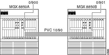
For this connection, use the ATM user service module (AUSM)-8T1 card as an Inverse Multiplexing for ATM (IMA) trunk to another AUSM-8T1 card. A connection is built from the RPM on one
MGX 8850 to the RPM on the other MGX 8850 across this IMA trunk.Figure 6-5 RPM-to-AUSM-8T1 IMA DAX Connection
Configuring the AUSM Interface
The following example shows an AUSM interface configuration.
/** MGX8850A **/mgx8850a.1.27.AUSMB8.a > addln 5mgx8850a.1.27.AUSMB8.a > addln 6mgx8850a.1.27.AUSMB8.a > addln 7mgx8850a.1.27.AUSMB8.a > addln 8Syntax : cnfln "line_num line_code line_len clk_src [E1-signaling]"line number -- values ranging from 1-8 are accepted, for AUSM-8T1/8E1, IMATM-T3T1/E3E1line code -- 2 for B8ZS (T1),3 for HDB3 (E1)line length -- 10-15 for T1, 8 for E1 with SMB module,9 for E1 with RJ48 line moduleclock source -- clock source : 1 for loop clock, 2 for local clockE1 signaling -- CCS: CCS, no CRC; CCS_CRC: CCS, with CRC;CLEAR: Clear E1mgx8850a.1.27.AUSMB8.a > cnfln 5 2 10 2mgx8850a.1.27.AUSMB8.a > cnfln 6 2 10 2mgx8850a.1.27.AUSMB8.a > cnfln 7 2 10 2mgx8850a.1.27.AUSMB8.a > cnfln 8 2 10 2Syntax : addimagrp (or addaimgrp) "group_num port_type list_of_lines minNumLinks"IMA group number -- value ranging from 1 to 8Port Type -- 1 - UNI, 2 - NNIList of links -- list of links separated by dotsminimum no of links -- minimum number of links for the group formation :value ranging from 1 to 8mgx8850a.1.27.AUSMB8.a > addimagrp 5 1 5.6.7.8 2Syntax : cnfimagrp (or cnfaimgrp) "grp max_diff_delay min_num_links"IMA group number -- value ranging from 1 to 8Max diff delay -- value between 0 and 275 for AUSM 8T1; btwn 0 and 200 for AUSM 8E1minimum no of links -- minimum number of links for the group formation :value ranging from 1 to 8mgx8850a.1.27.AUSMB8.a > cnfimagrp 5 150 2/** MGX8850B **/mgx8850b.1.27.AUSMB8.a > addln 5mgx8850b.1.27.AUSMB8.a > addln 6mgx8850b.1.27.AUSMB8.a > addln 7mgx8850b.1.27.AUSMB8.a > addln 8mgx8850b.1.27.AUSMB8.a > cnfln 5 2 10 2mgx8850b.1.27.AUSMB8.a > cnfln 6 2 10 2mgx8850b.1.27.AUSMB8.a > cnfln 7 2 10 2mgx8850b.1.27.AUSMB8.a > cnfln 8 2 10 2mgx8850b.1.27.AUSMB8.a > addimagrp 6 1 5.6.7.8 2mgx8850b.1.27.AUSMB8.a > cnfimagrp 6 150 2mgx8850b.1.27.AUSMB8.a > dspimagrp 6IMA Group number : 6Port type : UNILines configured : 5.6.7.8Enable : ModifyIMA Port state : ActiveIMA Group Ne state : operationalPortSpeed (cells/sec) : 14364GroupTxAvailCellRate (cells/sec) : 14364ImaGroupTxFrameLength(cells) : 128LcpDelayTolerance (IMA frames) : 1ReadPtrWrPtrDiff (cells) : 4Minimun number of links : 2MaxTolerableDiffDelay (msec) : 150Lines Present : 5.6.7.8ImaGroupRxImaId : 0x4ImaGroupTxImaId : 0x5Observed Diff delay (msec) : 0Clock Mode : CTCGroupAlpha : 2GroupBeta : 2GroupGamma : 1GroupConfiguration : 1IMAGrp Failure status : No FailureTiming reference link : 5Configuring the Router Interface
The following example shows a router interface configuration.
/** WSW-8850A-RPM **/wsw-8850a-rpm#conf tEnter configuration commands, one per line. End with CNTL/Z.wsw-8850a-rpm(config)#int sw 1.900 pwsw-8850a-rpm(config-subif)#ip address 10.97.90.1 255.255.255.0wsw-8850a-rpm(config-subif)#pvc RPM-IMA_Trunk 0/900wsw-8850a-rpm(config-if-atm-)#abr 96 64wsw-8850a-rpm(config-if-atm-)#encap aal5snapwsw-8850a-rpm(config-if-atm-)#^Z/** WSW-8850B-RPM **/wsw-8850b-rpm#conf tEnter configuration commands, one per line. End with CNTL/Z.wsw-8850b-rpm(config)#int sw 1.901 pwsw-8850b-rpm(config-subif)#ip addr 10.97.90.2 255.255.255.0wsw-8850b-rpm(config-subif)#pvc RPM-IMA_TRUNK 0/901wsw-8850b-rpm(config-if-atm-)#abr 96 64wsw-8850b-rpm(config-if-atm-)#encap aal5snapwsw-8850b-rpm(config-if-atm-)#^ZBuilding the RPM-to-AUSM-IMA Slave Connection
The following example shows how to build the RPM to AUSM-IMA slave connection.
/** WSW-8850A-RPM **/wsw-8850a-rpm#conf tEnter configuration commands, one per line. End with CNTL/Z.wsw-8850a-rpm(config)#addcon vcc switch 1.900 900 rname mgx8850a rslot 27 5 10 90wsw-8850a-rpm(config)#^Zwsw-8850a-rpm#sh sw conn vcc 900----------------------------------------------------------Local Sub-Interface : 900Local VPI : 0Local VCI : 900Remote Node Name : mgx8850aRemote Slot : 27Remote Interface : 5Remote VPI : 10Remote VCI : 90Routing Priority : 0Max Cost : 255Restricted Trunk Type : nonePercent Util : 100Remote PCR : 227Remote MCR : 151Remote Percent Util : 100Connection Master : RemoteSynch Status : inSynch/** WSW-8850B-RPM **/wsw-8850b-rpm#conf tEnter configuration commands, one per line. End with CNTL/Z.wsw-8850b-rpm(config)#addcon vcc switch 1.901 901 rname mgx8850b rslot 27 6 10 90wsw-8850b-rpm(config)#^Zwsw-8850b-rpm#sh sw conn vcc 901----------------------------------------------------------Local Sub-Interface : 901Local VPI : 0Local VCI : 901Remote Node Name : mgx8850bRemote Slot : 27Remote Interface : 6Remote VPI : 10Remote VCI : 90Routing Priority : 0Max Cost : 255Restricted Trunk Type : nonePercent Util : 100Remote PCR : 227Remote MCR : 151Remote Percent Util : 100Connection Master : RemoteSynch Status : inSynchBuilding the AUSM-IMA-to-AUSM-IMA Trunk Connection
The following example shows how to build the AUSM-IMA to AUSM-IMA trunk connection.
/** MGX8850A **/Syntax : addcon "port_num vpi vci conn_type service_type [Controller_Type] [mastership] [remoteConnId] "port number -- values ranging from 1-8Channel VPI -- Virtual Path Identifier: 0 - 255Channel VCI -- Virtual Channel Identifier: 0 - 65535 for VCC, * for VPCConnection Type -- Connection Type : 0 - VCC , non zero - LocalVP Id of the VPC (1 to 1000)Service Type -- Service Type: 1 - CBR, 2 - VBR, 3 - ABR, 4 - UBRController Type (Signaling) -- 1: PVC (PAR) - Default , 2: SPVC (PNNI)Mastership -- 1 for master, 2 for slave Default:SlaveRemote end Connection ID -- Format : NodeName.SlotNo.PortNo.ExternalConnIdmgx8850a.1.27.AUSMB8.a > addcon 5 10 90 0 3 1 1 mgx8850a.10.1.0.900Syntax : cnfupcabr "Port.VPI.VCI enable pcr[0+1] cdvt[0+1] scr scr_policembs IngPcUtil EgSrvRate EgPcUtil clp_tag "Port.VPI.VCI -- A unique Port.VPI.VCI identifying a connectionEnable/Disable -- UPC : 1 - Disable, 2 - EnablePeakCellRate -- PCR [0+1]: 10-PortRate(T1-3622,E1-4528,clearE1-4830),For IMA,T1-3591,E1-4490,clrE1-4789, multiply rate by #linksCDVT[0+1] -- Cell Delay Variation [0+1]: 1 - 250000 micro_secsSCR -- Sustained Cell Rate:10-PortRate(T1-3622,E1-4528,clearE1- 4830),For IMA,T1-3591,E1-4490,ClrE1-4789, multiply rate by #linksSCR Policing -- 1 - CLP[0] Cells, 2 - CLP[0+1] Cells, 3 - No SCR PolicingMaximum Burst -- 1 - 5000 cellsIngPcUtil -- Ingress percentage util: 1 to 127. 0 for defaultEgSrvRate -- Egress service rate:1-PortRate(T1-3622,E1-4528,clearE1-4830)For IMA,T1-3591,E1-4490,clrE1-4789, multiply rate by #links.EgPcUtil -- Egress percentage util: 1 to 127. 0 for defaultClp Tagging -- CLP TAG Enable : 1 - Disable, 2 - Enablemgx8850a.1.27.AUSMB8.a > cnfupcabr 5.10.90 2 227 1000 151 2 38 0 227 0 1/** MGX8850B **/mgx8850b.1.27.AUSMB8.a > addcon 6 10 90 0 3 1 1 mgx8850b.10.1.0.901mgx8850b.1.27.AUSMB8.a > cnfupcabr 6.10.90 2 227 1000 151 2 38 0 227 0 1Verifying the Configuration
The following example shows a ping from RPM to RPM. In this example, more than 15 cells have gone out. Because this is an available bit rate (ABR) connection, Resource Management cells will be present on the link.
/** WSW-8850A-RPM **/wsw-8850a-rpm#ping 10.97.90.2Type escape sequence to abort.Sending 5, 100-byte ICMP Echos to 10.97.90.2, timeout is 2 seconds:!!!!!Success rate is 100 percent (5/5), round-trip min/avg/max = 20/25/32 ms/** MGX8850A **/mgx8850a.1.27.AUSMB8.a > dspchancnt 5.10.90ChanNum: 18ChannelState: ActiveChannelEgressRcvState: NormalChannelEgressXmitState: NormalChannelIngressRcvState: NormalChannelIngressXmtState: NormalChanInServiceSeconds: 534ChanIngressPeakQDepth(cells): 1ChanIngressReceiveCells: 17ChanIngressClpSetCells: 0ChanIngressEfciSetRcvCells: 0ChanIngressEfciSetXmtCells: 0ChanIngressUpcClpSetCells: 0ChanIngressQfullDiscardCells: 0ChanIngressClpSetDiscardCells: 0ChanIngressTransmitCells: 17ChanShelfAlarmDiscardCells: 0ChanEarlyPacketDiscardCells: 0ChanPartialPacketDiscardCells: 0ChanIngressTransmitAAL5Frames: 5ChanIngressReceiveCellRate(cells/sec): 0ChanIngressReceiveUtilization(percentage): 0ChanIngressTransmitCellRate(cells/sec): 0ChanIngressTransmitUtilization(percentage): 0ChanEgressReceiveCellRate(cells/sec): 0ChanEgressReceiveUtilization(percentage): 0ChanEgressPortQFullDiscardCells: 0ChanEgressPortQClpThreshDiscardCells: 0ChanTransmitFifoFullCount (per card): 0/** MGX8850B **/mgx8850b.1.27.AUSMB8.a > dspchancnt 6.10.90ChanNum: 27ChannelState: ActiveChannelEgressRcvState: NormalChannelEgressXmitState: NormalChannelIngressRcvState: NormalChannelIngressXmtState: NormalChanInServiceSeconds: 184ChanIngressPeakQDepth(cells): 1ChanIngressReceiveCells: 17ChanIngressClpSetCells: 0ChanIngressEfciSetRcvCells: 0ChanIngressEfciSetXmtCells: 0ChanIngressUpcClpSetCells: 0ChanIngressQfullDiscardCells: 0ChanIngressClpSetDiscardCells: 0ChanIngressTransmitCells: 17ChanShelfAlarmDiscardCells: 0ChanEarlyPacketDiscardCells: 0ChanPartialPacketDiscardCells: 0ChanIngressTransmitAAL5Frames: 5ChanIngressReceiveCellRate(cells/sec): 0ChanIngressReceiveUtilization(percentage): 0ChanIngressTransmitCellRate(cells/sec): 0ChanIngressTransmitUtilization(percentage): 0ChanEgressReceiveCellRate(cells/sec): 0ChanEgressReceiveUtilization(percentage): 0ChanEgressPortQFullDiscardCells: 0ChanEgressPortQClpThreshDiscardCells: 0ChanTransmitFifoFullCount (per card): 0/** WSW-8850B-RPM **/wsw-8850b-rpm#deb ip pack detIP packet debugging is on (detailed)*Jan 4 21:26:45.636: IP: s=10.97.90.1 (Switch1.901), d=10.97.90.2 (Switch1.901), len 100, rcvd 3*Jan 4 21:26:45.636: ICMP TYPE=8, code=0*Jan 4 21:26:45.636:*Jan 4 21:26:45.636: IP: s=10.97.90.2 (local), d=10.97.90.1 (Switch1.901), len 100, sending*Jan 4 21:26:45.636: ICMP TYPE=0, code=0*Jan 4 21:26:45.636:*Jan 4 21:26:45.660: IP: s=10.97.90.1 (Switch1.901), d=10.97.90.2 (Switch1.901), len 100, rcvd 3*Jan 4 21:26:45.660: ICMP TYPE=8, code=0*Jan 4 21:26:45.660:*Jan 4 21:26:45.660: IP: s=10.97.90.2 (local), d=10.97.90.1 (Switch1.901), len 100, sending*Jan 4 21:26:45.660: ICMP TYPE=0, code=0*Jan 4 21:26:45.660:
Note
Note
RPM-to-FRSM-2CT3 ATM/PPP DAX Connection
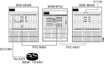
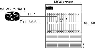
In the following example, a Cisco 7576 router transmits IPX datagrams out of a channelized DS3 port adapter using PPP encapsulation. The PPP frames are received on an FRSM-2CT3 service module that uses a frame forwarding connection to convert the frames to ATM cells. The cells are received by the RPM on the switch interface, and the datagrams are reintegrated through the aal5ciscoppp encapsulation.
Figure 6-6 RPM-to-FRSM-2CT3 ATM/PPP DAX Connection
Configuring the FRSM-2CT3 Interface
The following example shows how to configure the FRSM-2CT3 interface.
mgx8850b.1.5.VHS2CT3.a > addln 1Syntax : cnfln "line_num line_type clk_src "DS1 line number -- value range from 1 to 56DS1 line type -- 1 = dsx1ESF 2 = dsx1D4clock source -- clock source : 1 for loop clock, 2 for local clockmgx8850b.1.5.VHS2CT3.a > cnfln 2 1 2Syntax : addport "port_num line_num ds0_speed begin_slot num_slot port_ type"port number -- values ranging from 1-2( 2T3/2E3/HS2), 1-256 (2CT3)port line number -- value ranging from 1 to 56DS0 speed -- 1 for 56K, 2 for 64Kbeginning slot -- beginning time slot in 1 basenumber of slot -- number of DS0 time slots assigned toport type -- values 1-3, 1=frame relay, 2=FUNI mode-1a, 3=frForwardmgx8850b.1.5.VHS2CT3.a > addport 20 2 2 1 12 3Configuring the RPM Interface
The following example shows how to configure the RPM interface.
wsw-8850b-rpm#conf tEnter configuration commands, one per line. End with CNTL/Z.wsw-8850b-rpm(config)#ipx routingwsw-8850b-rpm(config)#ipx internal DD0000wsw-8850b-rpm(config)#username wsw-7576ah pass ciscowsw-8850b-rpm(config)#int virtual-Template 1wsw-8850b-rpm(config-if)#ipx ipxwanwsw-8850b-rpm(config-if)#ppp auth chapwsw-8850b-rpm(config-if)#int sw 1.1100 pwsw-8850b-rpm(config-subif)#pvc PPP-ATM-FRSM 0/1100wsw-8850b-rpm(config-if-atm-)#encap aal5ciscoppp virtual-Template 1wsw-8850b-rpm(config-if-atm-)#vbr-nrt 768 512 600wsw-8850b-rpm(config-if-atm-)#^ZConfiguring the Router Interface
The following example shows how to configure the router interface.
wss-7576ah#conf tEnter configuration commands, one per line. End with CNTL/Z.wss-7576ah(config)#ipx routingwss-7576ah(config)#ipx internal AB0000wss-7576ah(config)#controller T3 11/0/0wss-7576ah(config-controller)#t1 2 channel-group 0 timeslots 1-12 speed 64wss-7576ah(config-controller)#t1 2 fram esfwss-7576ah(config-controller)#t1 2 clock source linewss-7576ah(config-controller)#int s 11/0/0/2:0wss-7576ah(config-if)#encap pppwss-7576ah(config-if)#ipx ipxwanwss-7576ah(config-if)#ppp auth chapwss-7576ah(config-if)#username wsw-8850b-rpm pass ciscowss-7576ah(config)#^ZBuilding the FRSM-2CT3 Slave Connection
The following example shows how to build the FRSM-2CT3 slave connection.
Syntax : addcon "port dlci cir chan_type serv_type [CAC] [Controller_Type] [mastership]
[remoteConnId]"
port number -- values ranging from 1-2( 2T3/2E3/HS2), 1-256 (2CT3)DLCI number -- value ranging from 0-1023(2CT3/2T3/2E3/HS2)committed rate -- 0-1536000 bps for 2CT3; 0-44210000 bps for 2T3;0-34010000 bps for 2E3 , 0-51840000 bps for HS2chan type -- values 1-5, 1=NIW 2=SIW-transparent 3=SIW-xlation4=FUNI 5=frForwardEgress service type -- 1 = highpriorityQ 2 = rtVBRQ3 = nrtVBRQ 4 = aBRQ5 = uBRQCAC -- Connection Admission Control (optional); 1 = enable, 2 = disable (default)Controller Type (Signaling) -- 1: PVC (PAR) - Default , 2: SPVC (PNNI)mastership -- 1 for master, 2 for slaveRemote end Connection ID -- Format :NodeName.SlotNo.PortNo.Dlci ORNodeName.SlotNo.PortNo.ControllerId.Dlci for FR end point ORNodeName.SlotNo.PortNo.VPI.VCI for ATM end point.Where controller ID can be 1(PAR),2(PNNI),3(TAG)mgx8850b.1.5.VHS2CT3.a > addcon 20 200 512000 5 3 2 1 2Local Connection Id is : mgx8850b.5.20.0.1000Building the RPM Connection
The following example shows how to build the RPM connection.
wsw-8850b-rpm#conf tEnter configuration commands, one per line. End with CNTL/Z.wsw-8850b-rpm(config)#addcon vcc sw 1.1100 1100 rname mgx8850b rslot 5 20 0 1000 master localwsw-8850b-rpm(config-if-atm-)#^ZVerifying the Configuration
Enter the show ipx route command to view the contents of the IPX routing table and then enter the ping command to verify that you have a good connection, as shown in the following example.
wsw-8850b-rpm#sh ipx routeCodes: C - Connected primary network, c - Connected secondary networkS - Static, F - Floating static, L - Local (internal), W - IPXWANR - RIP, E - EIGRP, N - NLSP, X - External, A - Aggregates - seconds, u - uses, U - Per-user static2 Total IPX routes. Up to 1 parallel paths and 16 hops allowed.No default route known.L DD0000 is the internal networkR AB0000 [07/01] via 0.00ab.0000.0000, 27s, Vi1wsw-8850b-rpm#ping ipx ab0000.0000.0000.0001Type escape sequence to abort.Sending 5, 100-byte IPXcisco Echoes to AB0000.0000.0000.0001, timeout is 2 seconds:!!!!!Success rate is 100 percent (5/5), round-trip min/avg/max = 4/5/8 ms
Note
Note
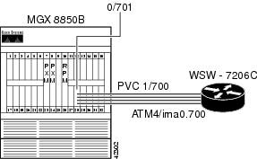
RPM-to-AUSM-8T1 ATM-IMA DAX Connection
The example below shows an IP connection between an RPM blade and a Cisco 7200 (see Figure 6-7). The Cisco 7200 hooks into the MGX 8850 through an IMA Port Adapter (PA) connected through four T1 lines to the AUSM-8T1 card in slot 28.
Figure 6-7 RPM-to-AUSM-8T1 ATM-IMA DAX Connection
Configuring the AUSM Interface
The following example shows how to configure the AUSM interface.
mgx8850b.1.28.AUSMB8.a > addln 5mgx8850b.1.28.AUSMB8.a > addln 6mgx8850b.1.28.AUSMB8.a > addln 7mgx8850b.1.28.AUSMB8.a > addln 8Syntax : cnfln "line_num line_code line_len clk_src [E1-signaling]"line number -- values ranging from 1-8 are accepted, for AUSM-8T1/8E1, IMATM-T3T1/E3E1line code -- 2 for B8ZS (T1),3 for HDB3 (E1)line length -- 10-15 for T1, 8 for E1 with SMB module,9 for E1 with RJ48 line moduleclock source -- clock source : 1 for loop clock, 2 for local clockE1 signaling -- CCS: CCS, no CRC; CCS_CRC: CCS, with CRC;CLEAR: Clear E1mgx8850b.1.28.AUSMB8.a > cnfln 5 2 10 2mgx8850b.1.28.AUSMB8.a > cnfln 6 2 10 2mgx8850b.1.28.AUSMB8.a > cnfln 7 2 10 2mgx8850b.1.28.AUSMB8.a > cnfln 8 2 10 2Syntax : addimagrp (or addaimgrp) "group_num port_type list_of_lines minNumLinks"IMA group number -- value ranging from 1 to 8Port Type -- 1 - UNI, 2 - NNIList of links -- list of links separated by dotsminimum no of links -- minimum number of links for the group formation :value ranging from 1 to 8mgx8850b.1.28.AUSMB8.a > addimagrp 1 1 5.6.7.8 2mgx8850b.1.28.AUSMB8.a > dspaimgrp 1IMA Group number : 1Port type : UNILines configured : 5.6.7.8Enable : EnabledIMA Port state : ActiveIMA Group Ne state : operationalPortSpeed (cells/sec) : 14364GroupTxAvailCellRate (cells/sec) : 14364ImaGroupTxFrameLength(cells) : 128LcpDelayTolerance (IMA frames) : 1ReadPtrWrPtrDiff (cells) : 4Minimun number of links : 2MaxTolerableDiffDelay (msec) : 275Lines Present : 5.6.7.8ImaGroupRxImaId : 0x0ImaGroupTxImaId : 0x0Observed Diff delay (msec) : 0Clock Mode : CTCGroupAlpha : 2GroupBeta : 2GroupGamma : 1GroupConfiguration : 1IMAGrp Failure status : No FailureTiming reference link : 5Configuring the Cisco 7200 Router Interface
The following example shows how configure the layer 1 parameters for the IMA bundle on the Cisco 7200, create the IMA interface, and add the layer 3 addressing.
wsw-7206c#conf tEnter configuration commands, one per line. End with CNTL/Z.wsw-7206c(config)#int atm 4/0wsw-7206c(config-if)#fram esfwsw-7206c(config-if)#line b8wsw-7206c(config-if)#clock source linewsw-7206c(config-if)#lbo short 133wsw-7206c(config-if)#ima 0wsw-7206c(config-if)#int atm 4/1wsw-7206c(config-if)#fram esfwsw-7206c(config-if)#line b8wsw-7206c(config-if)#clock source linewsw-7206c(config-if)#lbo short 133wsw-7206c(config-if)#ima 0wsw-7206c(config-if)#int atm 4/2wsw-7206c(config-if)#fram esfwsw-7206c(config-if)#line b8wsw-7206c(config-if)#clock source linewsw-7206c(config-if)#lbo short 133wsw-7206c(config-if)#ima 0wsw-7206c(config-if)#int atm 4/3wsw-7206c(config-if)#fram esfwsw-7206c(config-if)#line b8wsw-7206c(config-if)#clock source linewsw-7206c(config-if)#lbo short 133wsw-7206c(config-if)#ima 0wsw-7206c(config-if)#int atm 4/ima0wsw-7206c(config-if)#ima active-links-minimum 2wsw-7206c(config-if)#ima clock comm 0wsw-7206c(config-if)#ima diff 125wsw-7206c(config-if)#int atm4/ima0.700 pwsw-7206c(config-subif)#ip address 10.97.70.1 255.255.255.0wsw-7206c(config-subif)#pvc WSW-8850B-RPM 1/700wsw-7206c(config-if-atm-vc)#encap aal5snapwsw-7206c(config-if-atm-vc)#vbr-nrt 128 96 38wsw-7206c(config-if-atm-vc)#int atm 4/0wsw-7206c(config-if)#no shutwsw-7206c(config-if)#int atm 4/1wsw-7206c(config-if)#no shutwsw-7206c(config-if)#int atm 4/2wsw-7206c(config-if)#no shutwsw-7206c(config-if)#int atm 4/3wsw-7206c(config-if)#no shutwsw-7206c(config-if)#^ZConfiguring the RPM Interface
The following example shows how to configure the RPM interface.
wsw-8850b-rpm#conf tEnter configuration commands, one per line. End with CNTL/Z.wsw-8850b-rpm(config)#int sw 1.701 pwsw-8850b-rpm(config-subif)#ip addr 10.97.70.2 255.255.255.0wsw-8850b-rpm(config-subif)#PVC WSW-7206C-IMA 0/701wsw-8850b-rpm(config-if-atm-)#encapsulation aal5snapwsw-8850b-rpm(config-if-atm-)#vbr-nrt 128 96 38wsw-8850b-rpm(config-if-atm-)#exitwsw-8850b-rpm(config-subif)#^ZBuilding the AUSM Slave Connection
The following example shows how to build the AUSM slave connection.
Syntax : addcon "port_num vpi vci conn_type service_type [Controller_Type] [mastership]
[remoteConnId]
port number -- values ranging from 1-8Channel VPI -- Virtual Path Identifier: 0 - 255Channel VCI -- Virtual Channel Identifier: 0 - 65535 for VCC, * for VPCConnection Type -- Connection Type : 0 - VCC , non zero - LocalVP Id of the VPC (1 to 1000)Service Type -- Service Type: 1 - CBR, 2 - VBR, 3 - ABR, 4 - UBRController Type (Signaling) -- 1: PVC (PAR) - Default , 2: SPVC (PNNI)Mastership -- 1 for master, 2 for slave Default:SlaveRemote end Connection ID -- Format : NodeName.SlotNo.PortNo.ExternalConnIdmgx8850b.1.28.AUSMB8.a > addcon 1 1 700 0 2 1 2Local Connection Id is : mgx8850b.28.1.1.700Syntax : cnfupcvbr "Port.VPI.VCI enable pcr[0+1] cdvt[0+1] scr scr_policembs IngPcUtil EgSrvRate EgPcUtil clp_tag "Port.VPI.VCI -- A unique Port.VPI.VCI identifying a connectionEnable/Disable -- UPC : 1 - Disable, 2 - EnablePeakCellRate -- PCR [0+1]: 10-PortRate(T1-3622,E1-4528,clearE1-4830),For IMA,T1-3591,E1-4490,clrE1-4789, multiply rate by #linksCDVT[0+1] -- Cell Delay Variation [0+1]: 1 - 250000 micro_secsSCR -- Sustained Cell Rate:10-PortRate(T1-3622,E1-4528,clearE1- 4830),For IMA,T1-3591,E1-4490,ClrE1-4789, multiply rate by #linksSCR Policing -- 1 - CLP[0] Cells, 2 - CLP[0+1] Cells, 3 - No SCR PolicingMaximum Burst -- 1 - 5000 cellsIngPcUtil -- Ingress percentage util: 1 to 127. 0 for defaultEgSrvRate -- Egress service rate:1-PortRate(T1-3622,E1-4528,clearE1-4830)For IMA,T1-3591,E1-4490,clrE1-4789, multiply rate by #links.EgPcUtil -- Egress percentage util: 1 to 127. 0 for defaultClp Tagging -- CLP TAG Enable : 1 - Disable, 2 - Enablemgx8850b.1.28.AUSMB8.a > cnfupcvbr 1.1.700 2 302 1000 226 2 38 0 302 0 1Now build the RPM Master connection, as shown in the following example.
wsw-8850b-rpm#conf tEnter configuration commands, one per line. End with CNTL/Z.wsw-8850b-rpm(config)#addcon vcc sw 1.701 701 rname mgx8850b rslot 28 1 1 700 master localwsw-8850b-rpm(config)#^ZVerifying the Configuration
Enter the ping command to verify that you have a good connection.
wsw-8850b-rpm#ping 10.97.70.1Type escape sequence to abort.Sending 5, 100-byte ICMP Echos to 10.97.70.1, timeout is 2 seconds:!!!!!Success rate is 100 percent (5/5), round-trip min/avg/max = 16/18/20 ms
Note
Note
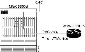
RPM-to-AUSM-8T1/B ATM/ATM DAX Connection
Establish IP connectivity between a Cisco MC3810 router and the RPM blade on the MGX 8850. In the following example, we have configured the Multi-Flex Trunk (MFT) on the 3810 (Controller T1 0) for ATM (logical interface ATM 0). The MFT is connected to the physical line 1 on the AUSM-8T1/B in slot 27 on the MGX 8850. A DAX connection is built through the PXM to switch cells between the AUSM and the RPM switch interface.
Figure 6-8 RPM-to-AUSM-8T1/B ATM/ATM DAX Connection
Configuring the AUSM Interface
The following example shows how to configure the AUSM interface. To do this, enable the physical line, enable a logical port on the line, adjust parameters as necessary, and enable payload scrambling on the line.
mgx8850b.1.27.AUSMB8.a > addln 1mgx8850b.1.27.AUSMB8.a > dspln 1LineNum: 1LineConnectorType: RJ-48LineType: dsx1ESFLineEnable: EnabledLineCoding: dsx1B8ZSLineLength: 0-131 ftLineXmtClockSource: LocalTimingLineLoopbackCommand: NoLoopLineSendCode: NoCodeLineUsedTimeslotsBitMap: 0xffffffffLineLoopbackCodeDetection: codeDetectDisabledLineBERTEnable: DisableSyntax : addport "port_num port_type line_num"port number -- values ranging from 1-8Port Type -- 1 - UNI, 2 - NNIline number -- value ranging from 1 to 8mgx8850b.1.27.AUSMB8.a > addport 1 1 1mgx8850b.1.27.AUSMB8.a > dspport 1LogicalPortNumber: 1Port Enable: UPPort State: ActivePortType: UNIPhysicalPortNumber: 1CellFraming: ATMCellScramble: No ScramblePlpp Loopback: No LoopbackSingle-bit error correction: Disabledmgx8850b.1.27.AUSMB8.a > dspplpp 1PhysicalPortNumber: 1CellFraming: ATMCellScramble: No ScramblePlpp Loopback: No LoopbackSingle-bit error correction: DisabledSyntax : cnfplpp "phy_port_num loopback scramble singlebit_errcorr_ena"physical port number -- value should be between 1 to 8plpp loopback -- : 1- no loopback, 2- remote loopback, 3- local loopbackcell scramble -- cell scramble: 1: no scramble, 2: scramblesingle bit errcorr -- 1: disable, 2: enablemgx8850b.1.27.AUSMB8.a > cnfplpp 1 1 2 1Configuring the Router Interface
The following example shows how to configure the router interface. To do this, be sure to supply the appropriate physical, data-link, and network layer parameters. Because this is a Cisco 3810 with MFT and digital voice module (DVM), be sure to set the proper clocking from the interface that connects to the AUSM (controller T1 0). Also, be sure to configure the ATM interface for payload scrambling.
wsw-3810n#conf tEnter configuration commands, one per line. End with CNTL/Z.wsw-3810n(config)#network-clock base-rate 64kwsw-3810n(config)#network-clock-select 1 t1 0wsw-3810n(config)#controller t1 0wsw-3810n(config-controller)#framing esfwsw-3810n(config-controller)#linecode b8zswsw-3810n(config-controller)#clock source linewsw-3810n(config-controller)#mode atm*Mar 3 21:41:02.644: TDMB channel # 99 Timeslots ( X 48K, . 56K,* 64K, - skipped)0 1 2 3 4 5 6 7 8 9 0 1 2 3 4 5 6 7 8 9 0 1 2 3 4 5 6 7 8 9 0 1wsw-3810n(config-controller)#int atm 0wsw-3810n(config-if)#atm enable-payload-scramblingwsw-3810n(config-if)#int atm 0.400 pointwsw-3810n(config-subif)#pvc MGX8850B-AUSM8 20/400wsw-3810n(config-if-atm-vc)#ubr 64wsw-3810n(config-if-atm-vc)#ip address 10.97.172.1 255.255.255.0*Mar 3 21:44:41.893: Service Type: ATM peak rate provisioned UBRwsw-3810n(config-if)#exitwsw-3810n(config)#interface Loop 0wsw-3810n(config-if)#ip address 10.97.175.1 255.255.255.0wsw-3810n(config-if)#exitwsw-3810n(config)#router ospf 777wsw-3810n(config-router)#network 10.97.168.0 0.0.7.255 area 0/**In order to prevent clock slips, we need to make sure either the MFT or the DVM clocks the box, not both.**/wsw-3810n(config-router)#cont t1 1wsw-3810n(config-controller)#clock source internalwsw-3810n(config-controller)#^ZConfiguring the RPM Interface
The following example shows how to configure the RPM switch interface. Because the RPM operates like a PA-A3 on a Cisco 7200 router, it is configured accordingly. The following example also shows how to set the traffic shaping for unspecified bit rate (UBR) at 64000 bps PCR.
wsw-8850b-rpm#conf tEnter configuration commands, one per line. End with CNTL/Z.wsw-8850b-rpm(config)#int sw 1.400 pointwsw-8850b-rpm(config-subif)#ip addr 10.97.172.2 255.255.255.0/**The default MTU on the RPM is 4470 which will cause OSPF fits if we try to establish a connection toa 3810 ATM interface with an MTU of 1500.**/wsw-8850b-rpm(config-subif)#ip mtu 1500wsw-8850b-rpm(config-subif)#pvc WSW-3810N 0/401wsw-8850b-rpm(config-if-atm-)#ubr 64wsw-8850b-rpm(config-if-atm-)#router ospf 777wsw-8850b-rpm(config-router)#network 10.97.168.0 0.0.7.255 area 0wsw-8850b-rpm(config-router)#int loop 0wsw-8850b-rpm(config-if)#ip addr 10.97.174.1 255.255.255.0wsw-8850b-rpm(config-if)#^ZBuilding the AUSM Slave Connection
The following example shows how to build the AUSM slave connection.
Syntax : addcon "port_num vpi vci conn_type service_type [Controller_Type] [mastership]
[remoteConnId]"
port number -- values ranging from 1-8Channel VPI -- Virtual Path Identifier: 0 - 255Channel VCI -- Virtual Channel Identifier: 0 - 65535 for VCC, * for VPCConnection Type -- Connection Type : 0 - VCC , non zero - LocalVP Id of the VPC (1 to 1000)Service Type -- Service Type: 1 - CBR, 2 - VBR, 3 - ABR, 4 - UBRController Type (Signaling) -- 1: PVC (PAR) - Default , 2: SPVC (PNNI)Mastership -- 1 for master, 2 for slave Default:SlaveRemote end Connection ID -- Format : NodeName.SlotNo.PortNo.ExternalConnIdmgx8850b.1.27.AUSMB8.a > addcon 1 20 400 0 4 1 2Local Connection Id is : mgx8850b.27.1.20.400Syntax : cnfupcubr "Port.VPI.VCI enable pcr[0+1] cdvt[0+1] IngPcUtil clp_tag "Port.VPI.VCI -- A unique Port.VPI.VCI identifying a connectionEnable/Disable -- UPC : 1 - Disable, 2 - EnablePeakCellRate -- PCR [0+1]: 10-PortRate(T1-3622,E1-4528,clearE1-4830),For IMA,T1-3591,E1-4490,clrE1-4789, multiply rate by #linksCDVT[0+1] -- Cell Delay Variation [0+1]: 1 - 250000 micro_secsIngPcUtil -- Ingress percentage util: 1 to 127. 0 for defaultClp Tagging -- CLP TAG Enable : 1 - Disable, 2 - Enablemgx8850b.1.27.AUSMB8.a > cnfupcubr 1.20.400 2 151 10000 0 2mgx8850b.1.27.AUSMB8.a > dspcon 1.20.400ChanNum: 17RowStatus: ModConnectionType: VCCServiceType: UBRChanSvcFlag: PVCPortNum: 1VPI: 20VCI (For VCC): 400Local VPId(for VPC): 0EgressQNum: 4IngressQDepth(cells): 1000IngressDiscardOption: CLP hysterisisIngressFrameDiscardThreshold 1000IngressQCLPHigh(cells): 900IngressQCLPLow(cells): 800QCLPState: LOWIngressEfciThreshold(cells): 1000UPCEnable: EnabledPeakCellRate[0+1](cells/sec): 151CellDelayVariation[0+1]: 10000 (micro secs)PeakCellRate[0](cells/sec): 3622CellDelayVariation[0]: 250000 (micro secs)SustainedCellRate(cells/sec): 151MaximumBurstSize(cells): 1000SCRPolicing: CLP[0]CLPTagEnable: EnabledFrameGCRAEnable: DisableForesightEnable: DisableInitialBurstSize(cells): 0ForeSightPeakCellRate(cells/sec): 151MinimumCellRate(cells/sec): 0InitialCellRate(cells/sec): 0LocalRemoteLpbkState: DisableChanTestType: No TestChanTestState: Not In ProgressChanRTDresult: 65535 msIngress percentage util: 1Egress percentage util : 0Egress Service Rate: 0LocalVpi: 20LocalVci: 400LocalNSAP: 6d6778383835306200000000000000001b000100RemoteVpi: 0RemoteVci: 0RemoteNSAP: 5468697320697320612064756d6d79204e534150Mastership: SlaveVpcFlag: VccConnServiceType: UBRRoutingPriority: 1MaxCost: 255RestrictTrunkType: No RestrictionConnPCR: 151ConnMCR: 0ConnPercentUtil: 1Building the RPM Master Connection
The following example shows how to build the RPM master connection.
wsw-8850b-rpm#conf tEnter configuration commands, one per line. End with CNTL/Z.wsw-8850b-rpm(config)#addcon vcc switch 1.400 401 rname mgx8850b rslot 27 1 20 400 master localwsw-8850b-rpm(config)#^Zwsw-8850b-rpm#cc 7(session redirected)mgx8850b.1.7.PXM.a > dspconsThis End Node Name Other End Status10.1.0.401 mgx8850b 27.1.20.400 OK27.1.20.400 mgx8850b 10.1.0.401 OKVerifying the Configuration
Enter the show ip ospf neighbor command to view the OSPF-neighbor information on a per-interface basis. Then enter the ping command to verify that you have a good connection, as shown in the following example.
wsw-3810n#sh ip ospf neiNeighbor ID Pri State Dead Time Address Interface10.97.174.1 1 FULL/ - 00:00:34 10.97.172.2 ATM0.400wsw-3810n#ping 10.97.172.2Type escape sequence to abort.Sending 5, 100-byte ICMP Echos to 10.97.172.2, timeout is 2 seconds:!!!!!Success rate is 100 percent (5/5), round-trip min/avg/max = 36/36/36 msCaveats
The following caveats exist.
Note
Note
Note
Note

Warning
RPM-to-PXM Feeder Trunk Connections
In the configuration examples in this section, datagrams enter and leave an RPM, get switched on the local Processor Switching Module (PXM), and leave and enter through a feeder trunk on the PXM. The BPX 8600, attached to the MGX 8850, switches the ATM cells to either another feeder-attached MGX 8850, ATM-attached customer premises equipment (CPE), or a feeder-attached MGX 8220.
RPM-to-RPM Three-Segment Connection
In the following examples, IP connectivity is established between RPM blades on two different MGX 8850 nodes. A connection is configured on each RPM to the feeder trunk on its associated PXM. Then, a connection is built on the BPX to join the feeder segments.
Configuring the RPM Interfaces
The following example shows how to set the traffic shaping for unspecified bit rate (UBR) at 256000 bps peak cell rate (PCR).
/** WSW-8850A-RPM **/wsw-8850a-rpm#conf tEnter configuration commands, one per line. End with CNTL/Z.wsw-8850a-rpm(config)#int switch 1.300 pointwsw-8850a-rpm(config-subif)#ip addr 10.97.30.1 255.255.255.0wsw-8850a-rpm(config-subif)#pvc 8850b-rpm 0/3000wsw-8850a-rpm(config-if-atm-)#ubr 256wsw-8850a-rpm(config-if-atm-)#^Z/** WSW-8850B-RPM **/wsw-8850b-rpm#conf tEnter configuration commands, one per line. End with CNTL/Z.wsw-8850b-rpm(config)#int switch 1.300 pointwsw-8850b-rpm(config-subif)#ip addr 10.97.30.2 255.255.255.0wsw-8850b-rpm(config-subif)#pvc 8850a-rpm 0/3001wsw-8850b-rpm(config-if-atm-)#ubr 256wsw-8850b-rpm(config-if-atm-)#^ZAdding the RPM-to-Trunk Connections
The following example shows how to add the RPM to trunk connections.
/** WSW-8850A-RPM **/wsw-8850a-rpm#conf tEnter configuration commands, one per line. End with CNTL/Z.wsw-8850a-rpm(config)#addcon vcc sw 1.300 3000 rname mgx8850a rslot 0 1 30 3100 master localwsw-8850a-rpm(config)#^Zwsw-8850a-rpm#sh switch connSynchlVpi lVci remoteNodeName remoteSlot remoteIf rVpi rVci Status0 3000 mgx8850a 0 1 30 3100 inSynchwsw-8850a-rpm#sh switch conn vcc 3000----------------------------------------------------------Local Sub-Interface : 300Local VPI : 0Local VCI : 3000Remote Node Name : mgx8850aRemote Slot : 0Remote Interface : 1Remote VPI : 30Remote VCI : 3100Routing Priority : 0Max Cost : 255Restricted Trunk Type : nonePercent Util : 100Remote PCR : 604Remote MCR : 604Remote Percent Util : 100Connection Master : LocalSynch Status : inSynch/** Since we have not built the BPX connection, our RPM-PXM connection willhave A-Bit issues **/wsw-8850a-rpm#cc 7(session redirected)mgx8850a.1.7.PXM.a > dspconsThis End Node Name Other End Status7.1.30.3100 mgx8850a 10.1.0.3000 FAILED ABIT ALARM10.1.0.3000 mgx8850a 7.1.30.3100 FAILED ABIT ALARM/** WSW-8850B-RPM **/wsw-8850b-rpm#conf tEnter configuration commands, one per line. End with CNTL/Z.wsw-8850b-rpm(config)#addcon vcc sw 1.300 3001 rname mgx8850b rslot 0 1 31 3101 master localwsw-8850b-rpm(config)#^Zwsw-8850b-rpm#sh swit conSynchlVpi lVci remoteNodeName remoteSlot remoteIf rVpi rVci Status0 3001 mgx8850b 0 1 31 3101 inSynchwsw-8850b-rpm#sh sw conn vcc 3001----------------------------------------------------------Local Sub-Interface : 300Local VPI : 0Local VCI : 3001Remote Node Name : mgx8850bRemote Slot : 0Remote Interface : 1Remote VPI : 31Remote VCI : 3101Routing Priority : 0Max Cost : 255Restricted Trunk Type : nonePercent Util : 100Remote PCR : 604Remote MCR : 604Remote Percent Util : 100Connection Master : LocalSynch Status : inSynchwsw-8850b-rpm#cc 7(session redirected)mgx8850b.1.7.PXM.a > dspconsThis End Node Name Other End Status7.1.31.3101 mgx8850b 10.1.0.3001 FAILED ABIT ALARM10.1.0.3001 mgx8850b 7.1.31.3101 FAILED ABIT ALARMAdding the Trunk-to-Trunk Connection
The following example shows how to add a trunk-to-trunk connection, including the commands that must be entered to create this connection.
wsw-bpx3 TN StrataCom BPX 8620 9.2.10 July 29 1999 16:09 EDTFrom Remote Remote Route11.1.30.3100 NodeName Channel State Type Avoid COS O11.1.30.3100 wsw-bpx3 9.1.31.3101 Ok ubrLast Command: addcon 11.1.30.3100 wsw-bpx3 9.1.31.3101 ubr 604 * 5000 * *wsw-bpx3 TN StrataCom BPX 8620 9.2.10 July 29 1999 16:09 EDTConn: 11.1.30.3100 wsw-bpx3 9.1.31.3101 ubr Status:OKPCR(0+1) % Util CDVT(0+1) FBTC CLP Set604/604 1/1 5000/5000 y 1Path: Route information not applicable for local connectionswsw-bpx3 BXM : OK wsw-bpx3 BXM : OKLine 11.1 : OK Line 9.1 : OKOAM Cell RX: Clear NNI : OKNNI : OKThis Command: dspcon 11.1.30.3100Verifying the Configuration
Enter the ping command to verify that you have a good connection, as shown in the following example.
/** Ping from RPM to RPM **/wsw-8850a-rpm#ping 10.97.30.2Type escape sequence to abort.Sending 5, 100-byte ICMP Echos to 10.97.30.2, timeout is 2 seconds:!!!!!Success rate is 100 percent (5/5), round-trip min/avg/max = 8/11/12 ms/** Examine Channel Stats on BPX **/wsw-bpx3 TN StrataCom BPX 8620 9.2.10 July 29 1999 16:11 EDTChannel Statistics for 11.1.30.3100Cleared: July 29 1999 16:11 (-) SnapshotPCR: 604/604 cps Collection Time: 0 day(s) 00:00:13 Corrupted: NOTraffic Cells CLP Avg CPS %util Chan Stat Addr: 30F68D4CFrom Port : 2686 0 205 33 OAM Cell RX: ClearTo Network : 2686 --- 205 33From Network: 2699 0 206 34To Port : 2699 0 206 34Rx Frames Rcv : 29 NonCmplnt Dscd: 0 Rx Q Depth : 0Tx Q Depth : 0 Rx CLP0 : 2686 Rx Nw CLP0 : 2699Igr VSVD ACR : 0 Egr VSVD ACR : 0 Tx Clp0 Port : 2699Rx Clp0+1 Port: 2686 NCmp CLP0 Dscd: 0 NCmp CLP1 Dscd: 0Oflw CLP0 Dscd: 0 Oflw CLP1 Dscd: 0Last Command: dspchstats 11.1.30.3100 1/** Show Connections on PXMs - A-Bit alarms Disappear **/mgx8850a.1.7.PXM.a > dspconsThis End Node Name Other End Status7.1.30.3100 mgx8850a 10.1.0.3000 OK10.1.0.3000 mgx8850a 7.1.30.3100 OKmgx8850b.1.7.PXM.a > dspconsThis End Node Name Other End Status7.1.31.3101 mgx8850b 10.1.0.3001 OK10.1.0.3001 mgx8850b 7.1.31.3101 OK
Note
Note
RPM-to-FRSM-2E3 Three-Segment Connection
The FRSM uses the service interworking translation method to convert incoming Frame Relay frames to ATM cells. The ATM cells are switched out the PXM interface and switched between feeder trunks by the BPX. When the cells are received by the other PXM, they are switched to the switch interface on the RPM in the node where they are re-integrated back into IP datagrams.
In the example below, IP datagrams are transported through Frame Relay/ATM service interworking between a Frame Relay-attached router and an RPM. An unchannelized E3 port adapter is connected on a
Cisco 7576 router to line 1 on the Frame Relay Service Module (FRSM-2E3) in slot 3 of one MGX 8850.Figure 6-9 RPM-to-FRSM-2E3 Three-Segment Connection
Configuring the FRSM-2E3 Interface
The following example shows how to configure the FRSM-2E3 interface.
mgx8850b.1.3.VHS2E3.a > addln 1Syntax : cnfds3ln "line_num line_len clk_src "E3 line number -- value range from 1 to 2line length -- 1 for LessThan225ft,2 for GreaterThan225ftDsx3 Xmt Clock Src -- 1 : backplane-clk 2 : recovery-clk 3 : Local-clkmgx8850b.1.3.VHS2E3.a > cnfds3ln 1 1 1Syntax : addport "port_num line_num port_type "port number -- values ranging from 1-2( 2T3/2E3/HS2), 1-256 (2CT3)port line number -- value ranging from 1 to 2port type -- values 1-3, 1=frame relay, 2=FUNI mode-1a, 3=frForwardmgx8850b.1.3.VHS2E3.a > addport 1 1 1Syntax : cnfport "portNum lmiSig asyn ELMI T391 T392 N391 N392 N393"port number -- values ranging from 1-2( 2T3/2E3/HS2), 1-256 (2CT3)LMI signaling -- (N)one (S)trataLMI au-AnnexAUNIdu-AnnexDUNI an-AnnexANNI dn-AnnexDNNIasyn update -- (UPD = Update Status, UFS = Unsolicited Full Status)(n or 1) = both dis, (y or 2) = UPD en, 3 = UFS en, 4 = both enEnhanced LMI -- (N or n) disable (Y or y) enableT391 timer -- value ranging from 5 to 30 sec.T392 timer -- value ranging from 5 to 30 sec.N391 counter -- value ranging from 1 to 255N392 counter -- value ranging from 1 to 10N393 counter -- value ranging from 1 to 10, greater than N392mgx8850b.1.3.VHS2E3.a > cnfport 1 S n nmgx8850b.1.3.VHS2E3.a > dspds3ln 1LineNum: 1LineEnable: ModifyLineType: G.751LineCoding: e3HDB3LineLength: LT225ftLineSubRateEnable: DisableLineDsuSelect: dl3100ModeLineRate: 34368kbpsLineLoopbackCommand: NoLoopLineXmitClockSource: backplaneClkLineEqualizer: internal equalizerLineBertEnable: DisableSyntax : cnflnsubrate " line_num dsu_subrate_ena dsu_select dsu_line_rate "E3 line number -- value range from 1 to 2ds3 SubRate Enable -- 1 = disable, 2 = enableds3 Dsu Select -- 1 = dl3100Mode, 2 = adcKentroxModedsu Line Rate -- values ranging from 300 to 44736 in steps of 300kbps (dl3100Mode) or 500 Kbps (adcKentroxMode)mgx8850b.1.3.VHS2E3.a > cnflnsubrate 1 2 1 33900dsx3LineRate = 33900Configuring the Router Interface
The following example shows how to configure the router interface:
wss-7576ah#conf t Enter configuration commands, one per line. End with CNTL/Z. wss-7576ah(config)#int s 8/0/0wss-7576ah(config-if)#encap frame ietf wss-7576ah(config-if)#no shut wss-7576ah(config-if)#clock source linewss-7576ah(config-if)#dsu band 33900 wss-7576ah(config-if)#int s 8/0/0.950 p wss-7576ah(config-subif)#ip addr 10.97.95.2 255.255.255.0 wss-7576ah(config-subif)#frame-relay interface-dlci 950 wss-7576ah(config-fr-dlci)#^ZConfiguring the RPM Interface
The following example shows how to configure the RPM interface:
wsw-8850a-rpm#conf tEnter configuration commands, one per line. End with CNTL/Z.wsw-8850a-rpm(config)#int sw 1.951 pwsw-8850a-rpm(config-subif)#ip address 10.97.95.1 255.255.255.0wsw-8850a-rpm(config-subif)#PVC RPM-FRSM2E3 0/951wsw-8850a-rpm(config-if-atm-)#vbr-nrt 384 256 151wsw-8850a-rpm(config-if-atm-)#encap aal5snapwsw-8850a-rpm(config-if-atm-)#^ZBuilding the FRSM-2E3-to-Trunk Connection
The following example shows how to build the FRSM-2E3 to trunk connection.
Syntax : addcon "port dlci cir chan_type serv_type [CAC] [Controller_Type] [mastership]
[remoteConnId] "
port number -- values ranging from 1-2( 2T3/2E3/HS2), 1-256 (2CT3)DLCI number -- value ranging from 0-1023(2CT3/2T3/2E3/HS2)committed rate -- 0-1536000 bps for 2CT3; 0-44210000 bps for 2T3;0-34010000 bps for 2E3 , 0-51840000 bps for HS2chan type -- values 1-5, 1=NIW 2=SIW-transparent 3=SIW-xlation4=FUNI 5=frForwardEgress service type -- 1 = highpriorityQ 2 = rtVBRQ3 = nrtVBRQ 4 = aBRQ5 = uBRQCAC -- Connection Admission Control (optional); 1 = enable, 2 = disable (default)Controller Type (Signaling) -- 1: PVC (PAR) - Default , 2: SPVC (PNNI)mastership -- 1 for master, 2 for slaveRemote end Connection ID -- Format :NodeName.SlotNo.PortNo.Dlci ORNodeName.SlotNo.PortNo.ControllerId.Dlci for FR end point ORNodeName.SlotNo.PortNo.VPI.VCI for ATM end point.Where controller ID can be 1(PAR),2(PNNI),3(TAG)mgx8850b.1.3.VHS2E3.a > addcon 1 950 256000 3 3 2 1 1 mgx8850b.0.1.9.950mgx8850b.1.3.VHS2E3.a > dspchansDLCI Chan ServType I/EQDepth I/EQDEThre I/EECNThre Fst/ DE Type Alarm--------- ---- -------- ----- ----- ----- ----- ----- ----- --- --- ----- -----3.1.1.950 21 nrtVBR 1048575/1048575 524287/524287 104857/104857 Dis/Dis SIW-X YesSyntax : cnfchanpol "chan_num cir bc be ibs detag"channel number -- value ranging from 16-4015(2CT3), 16-2015( 2T3/2E3/HS2)committed rate -- 0-1536000 bps for 2CT3; 0-44210000 2T3;0-34010000 bps for 2E3; 0-51840000 bps for HS2committed burst -- 0-2097151 in bytesexcess burst -- 0-2097151 in bytesinitial burst -- 0-2097151 in bytes, Less than or equal to BcDE bit tagging -- 1 for enable, 2 for disablemgx8850b.1.3.VHS2E3.a > cnfchanpol 21 256000 32000 16000 8000 2Building the RPM-to-Trunk Connection
The following example shows how to build the RPM to trunk connection:
wsw-8850a-rpm#conf tEnter configuration commands, one per line. End with CNTL/Z.wsw-8850a-rpm(config)#addcon vcc switch 1.951 951 rname mgx8850a rslot 0 1 9 951 master localwsw-8850a-rpm(config)#^ZBuilding the Trunk-to-Trunk Connection
The following example shows how to configure a trunk-to-trunk connection, including the commands that must be entered to create this connection.
wsw-bpx3 TN StrataCom BPX 8620 9.2.10 Aug. 9 1999 10:09 EDTFrom Remote Remote Route11.1.9.951 NodeName Channel State Type Avoid COS O11.1.9.951 wsw-bpx3 9.1.9.950 Ok atfrLast Command: addcon 11.1.9.951 wsw-bpx3 9.1.9.950 atfr 906 * 1000 604 151 * * * *wsw-bpx3 TN StrataCom BPX 8620 9.2.10 Aug. 9 1999 10:09 EDTConn: 11.1.9.951 wsw-bpx3 9.1.9.950 atfr Status:OKPCR(0+1) % Util CDVT(0+1) SCR MBS906/906 100/100 1000/1000 604/604 151/151Policing VC Qdepth EFCI IBS3 1280/1280 35/35 1/1Path: Route information not applicable for local connectionswsw-bpx3 BXM : OK wsw-bpx3 BXM : OKLine 11.1 : OK Line 9.1 : OKOAM Cell RX: Clear NNI : OKNNI : OKThis Command: dspcon 11.1.9.951Verifying the Configuration
Enter the ping command to verify that you have a good connection, as shown in the following example.
/** The Ubiquitous Ping Test **/wsw-8850a-rpm#ping 10.97.95.2Type escape sequence to abort.Sending 5, 100-byte ICMP Echos to 10.97.95.2, timeout is 2 seconds:!!!!!Success rate is 100 percent (5/5), round-trip min/avg/max = 4/4/4 ms/** Examine Channel Stats on BPX **/wsw-bpx3 TN StrataCom BPX 8620 9.2.10 Aug. 9 1999 10:11 EDTChannel Statistics for 11.1.9.951 Cleared: Aug. 9 1999 10:11 (-)PCR: 906/906 cps Collection Time: 0 day(s) 00:00:06 Corrupted: NOTraffic Cells CLP Avg CPS %util Chan Stat Addr: 30F6933CFrom Port : 15 0 2 0 OAM Cell RX: ClearTo Network : 15 --- 2 0From Network: 15 0 2 0To Port : 15 0 2 0Rx Frames Rcv : 5 NonCmplnt Dscd: 0 Rx Q Depth : 0Tx Q Depth : 0 Rx CLP0 : 15 Rx Nw CLP0 : 15Igr VSVD ACR : 0 Egr VSVD ACR : 0 Tx Clp0 Port : 15Rx Clp0+1 Port: 15 NCmp CLP0 Dscd: 0 NCmp CLP1 Dscd: 0Oflw CLP0 Dscd: 0 Oflw CLP1 Dscd: 0This Command: dspchstats 11.1.9.951 1Caveats
The following caveats exist.
Note
Note
Note
Note
Connection Synchronization
Because connections are added separately to the RPM and to PXM or other RPM cards, connections may exist on the RPM but not on the PXM or the other RPM cards. Therefore, connection synchronization, which is also referred to as service module resynchronization, between the RPM and the other service modules is necessary.
Note
•
•
•
•
Manually Resynchronizing Connections
You can manually resynchronize connections. However, out of synchronization conditions may be triggered by
•
•
•
•
You can force resynchronization by entering the start_resynch command at the configure interface level as shown here:
NY_9# conf tNY_9(config)# int sw1NY-9(config-if)#switch start_resynchAutomatically Resynchronizing Connections
auto_synch corrects mismatches between the PXM and the RPM databases. If your network is highly unstable, do not turn on auto_synch.
The commands that are used to enable/disable the auto_synch feature are moved under the new switch command. Here is an example of how you use this command on the config level.
NY_9# conf tNY_9(config)# int sw1NY-9(config-if)#switch auto_synch on <off|manual> "default is off"Connection State Alarms
This section describes the alarm state of each PNNI, how alarms occur, and what they mean.
Endpoint status indicators reported by RPM and their meanings include:
•
•
•
•
These alarms are triggered when
•
•
Connection State Resynchronization
Connection state resynchronization is triggered by a PXM-1 switchover or an RPM reset. This happens when an alarm state is not persistent nor contains redundant data, and needs to be rebuilt after a switchover or reset.
 Feedback
Contact Cisco
- Open a Support Case

- (Requires a Cisco Service Contract)
This Document Applies to These Products
- Collaboration Endpoints - Retired Products
- Conferencing - Retired Products
- Contact Center - Retired Products
- Optical Networking - Retired Products
- Routers - Retired Products
- Security - Retired Products
- Servers - Unified Computing (UCS) Retired Products
- Storage Networking Retired Products
- Switches - Retired Products
- Video - Retired Products
- Wireless - Retired Products