Cisco Nexus 9808 Switch Overview
The Cisco 9808 switch includes:
-
The Cisco 9808 is a 16-RU switch that supports distributed forwarding across multiple field replaceable units (FRUs).
The documentation set for this product strives to use bias-free language. For the purposes of this documentation set, bias-free is defined as language that does not imply discrimination based on age, disability, gender, racial identity, ethnic identity, sexual orientation, socioeconomic status, and intersectionality. Exceptions may be present in the documentation due to language that is hardcoded in the user interfaces of the product software, language used based on RFP documentation, or language that is used by a referenced third-party product. Learn more about how Cisco is using Inclusive Language.
The Cisco 9808 switch includes:
The Cisco 9808 is a 16-RU switch that supports distributed forwarding across multiple field replaceable units (FRUs).
The following table describes the Cisco 9808 switch components, and the supported quantity.
|
Component |
Quantity |
|---|---|
|
Line cards |
8 |
|
Supervisor modules |
2 |
|
Fabric modules |
8 |
|
Fan trays |
4 |
|
Power trays |
3 |
|
Power supplies |
HVAC/HVDC—9 (3 per tray) DC60—12 (4 per tray) |
Cisco Nexus 9800 switches support the following line cards:
|
Line Card PIDs |
Transceivers |
|---|---|
|
N9K-X9836DM-A |
QSFP-DD / QSFP28 / QSFP+ |
|
N9K-X98900CD-A |
QSFP-DD / QSFP28 / QSFP+ |
 Note |
When unlocking the ejector button and then relocking it without removing the line card, the line card will power down. The line card will not power up and will not show poweroff module in command line interface. Preforming OIR is required to power up the line card. |
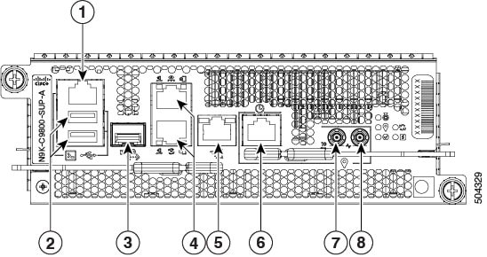
Cisco Nexus 9800 Supervisor modules (N9K-C9800-SUP-A and N9K-C9800-SUP-B) manage all control plane functions on the Cisco Nexus 9800 Series Switches.
|
1 |
Console RS-232 Serial Port RJ45 |
5 |
SyncE BITS/DTI/J.211 |
|
2 |
USB Port Type-A (2-ports). Port A gets detected ahead of Port B. Top: Port B Bottom: Port A |
6 |
G.703 Time-of-Day (TOD) |
|
3 |
Control Plane Expansion SFP/SFP+ port |
7 |
1.0/2.3 50 ohm connector for 10 MHz, input, and output |
|
4 |
Top: Management Ethernet (10/100/1000-Mbps) RJ-45 (Copper) port LAN. Bottom: IEEE 1588 Precision Time Protocol (PTP) |
8 |
1.0/2.3 50 ohm connector for 1 PPS, input, and output |

|
1 |
Control Plane Expansion SFP/SFP+ port
|
7 |
G.703 Time-of-Day (TOD) port |
||
|
2 |
IEEE 1588 Precision Time Protocol (PTP) port |
8 |
Global Navigation Satellite System (GNSS) port |
||
|
3 |
Console RS-232 Serial port RJ45 |
9 |
1.0/2.3 50 ohm connector for 1 PPS, input, and output |
||
|
4 |
USB port Type-A |
10 |
1.0/2.3 50 ohm connector for 10 MHz, input, and output |
||
|
5 |
Management Ethernet (10/100/1000-Mbps) RJ-45 (Copper) port LAN |
11 |
USB port Type-B. Port A gets detected ahead of port B |
||
|
6 |
SyncE BITS/DTI/J.211 port |
- |
- |
Cisco Nexus 9808 switches support the following fabric modules:
N9K-C9808-FM-A—Cisco Nexus 9808 Fabric Module
For temperature and physical specifications, refer to the Physical characteristics table in the Cisco Nexus 9800 Series Switches Data Sheet.
For chassis dimensions and weight, please refer to the following table.
|
Weight |
Unloaded: 162 lbs. (73 kg.) Fully loaded: 658 lbs. (299 kg.) |
|
Dimensions |
(H) 28 x (W) 17.45 x (D) 33.73 in. (71.12 x 44.32 x 85.7 cm.) |
|
Number of Rack Units |
16 RU |
The following table describes the maximum power consumption of supervisors, fabric modules, fan trays and line cards in Nexus 9808 chassis.
|
Component |
Maximum power / Unit |
|---|---|
|
Supervisor module (N9K-C9800-SUP-A) |
95 W |
|
Supervisor module (N9K-C9800-SUP-B) |
95 W |
|
Fabric module (N9K-C9808-FM-A) |
575 W |
|
Fan tray (N9K-C9808-FAN-A) |
686 W |
|
Line card (N9K-X9836DM-A – 36 port 400G QSFP-DD line card) |
2436 W |
|
Line card (N9K-X98900CD-A – 34 port 100G and 14 port 400G QSFP-DD line card) |
2436 W |
For more information, refer to the Cisco Nexus 9800 Series Switches Data Sheet.
To ensure proper airflow for the switch in your facility, position the switch with its air intake on a cold aisle and the air exhaust on a hot aisle.
The maximum power available for operations depends on the input power from your power source, the number and output capabilities of your power supplies, and the power redundancy mode that you use.
The following table lists the amount of power available for Cisco 9800 series switches from all available power trays.
|
Total Power Supply |
Combined Mode in Watts (No redundancy) |
N+1 Redundancy Mode in Watts (with Single Supply Loss) |
Total Power Tray |
|---|---|---|---|
|
1 |
6,300 |
— |
1 |
|
2 |
12,600 |
6,300 |
|
|
3 |
18,900 |
12,600 |
|
|
4 |
25,200 |
18,900 |
2 |
|
5 |
31,500 |
25,200 |
|
|
6 |
37,800 |
31,500 |
|
|
7 |
44,100 |
37,800 |
3 |
|
8 |
50,400 |
44,100 |
|
|
9 |
56,700 |
50,400 |
|
Total Power Supply |
Combined Mode in Watts (No redundancy) |
N+1 Redundancy Mode in Watts (with Single Supply Loss) |
N+N Redundancy Mode in Watts (with Feed Loss) |
Total Power Tray |
|---|---|---|---|---|
|
1 |
4,400 |
— |
2,200 |
1 |
|
2 |
8,800 |
4,400 |
4,400 |
|
|
3 |
13,200 |
8,800 |
6,600 |
|
|
4 |
17,600 |
13,200 |
8,800 |
|
|
5 |
22,000 |
17,600 |
11,000 |
2 |
|
6 |
26,400 |
22,000 |
13,200 |
|
|
7 |
30,800 |
26,400 |
15,400 |
|
|
8 |
35,200 |
30,800 |
17,600 |
|
|
9 |
39,600 |
35,200 |
19,800 |
3 |
|
10 |
44,000 |
39,600 |
22,000 |
|
|
11 |
48,400 |
44,000 |
24,200 |
|
|
12 |
52,800 |
48,400 |
26,400 |
|
Total Power Supply |
Combined Mode in Watts (No redundancy) |
N+1 Redundancy Mode in Watts (with Single Supply Loss) |
N+N Redundancy Mode in Watts (with Feed Loss) |
Total Power Tray |
|---|---|---|---|---|
|
1 |
4,800 |
— |
2,400 |
1 |
|
2 |
9,600 |
4,800 |
4,800 |
|
|
3 |
14,400 |
9,600 |
7,200 |
|
|
4 |
19,200 |
14,400 |
9,600 |
|
|
5 |
24,000 |
19,200 |
12,000 |
2 |
|
6 |
28,800 |
24,000 |
14,400 |
|
|
7 |
33,600 |
28,800 |
16,800 |
|
|
8 |
38,400 |
33,600 |
19,200 |
|
|
9 |
43,200 |
38,400 |
21,600 |
3 |
|
10 |
48,000 |
43,200 |
24,000 |
|
|
11 |
52,800 |
48,000 |
26,400 |
|
|
12 |
57,600 |
52,800 |
28,800 |
Note |
To determine which transceivers and cables are supported by this switch, refer to the Transceiver Module Group (TMG) Compatibility Matrix Tool: https://tmgmatrix.cisco.com/home
|
 Feedback