LEDs
You can perform the following check on LEDs that assist you with the troubleshooting process:
The documentation set for this product strives to use bias-free language. For the purposes of this documentation set, bias-free is defined as language that does not imply discrimination based on age, disability, gender, racial identity, ethnic identity, sexual orientation, socioeconomic status, and intersectionality. Exceptions may be present in the documentation due to language that is hardcoded in the user interfaces of the product software, language used based on RFP documentation, or language that is used by a referenced third-party product. Learn more about how Cisco is using Inclusive Language.
You can perform the following check on LEDs that assist you with the troubleshooting process:
The LEDs indicate whether each type of module (supervisor modules, line cards, fabric modules, fan trays, and power supplies) is fully functional or have a fault condition.
| LED | Color | Status |
|---|---|---|
|
ATTN (Attention)
|
Blue |
The operator has activated this LED to identify this chassis. |
|
Off |
The chassis is not functional. |
Each port on N9K-X98900CD-A (only) has an LED. The following table describes port status LEDs.
|
LED Color |
Description |
|---|---|
|
Off |
Port is administratively shut down. |
|
Green |
Port is administratively enabled and the link is up. |
|
Amber |
Port is administratively enabled and the link is down. |
|
Flashing Amber |
Port is faulty and disabled. |
The power supply LEDs are located on the front portion of the module.
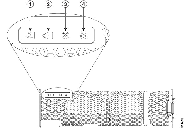
|
1 |
Input OK |
3 |
Fault |
|
2 |
Output OK |
4 |
ATTN (Attention) |
|
LED |
Color |
Status |
|---|---|---|
|
Input OK |
Green |
Both input voltages are present. |
|
Flashing Green |
Only one input power is present. |
|
|
Off |
No input power is present. |
|
|
Output OK |
Green |
Output power is enabled. |
|
Flashing Green |
Output power in power limit, or in overcurrent condition, or is in the sleep-mode.1 |
|
|
Off |
Output disabled, or no inputs present, or firmware upgrade in-progress. |
|
|
Fault |
Red |
Output voltage is out of the specified range, or a fan has failed, or internal fault. |
|
Flashing red |
Firmware upgrade in-progress. |
|
|
ATTN (Attention)
|
Flashing blue |
User configured action config hw-module attention-led location 0/PTx/PMy. |
|
Off |
No user configuration is set. |
The fan tray LEDs are located on the top portion of the module.
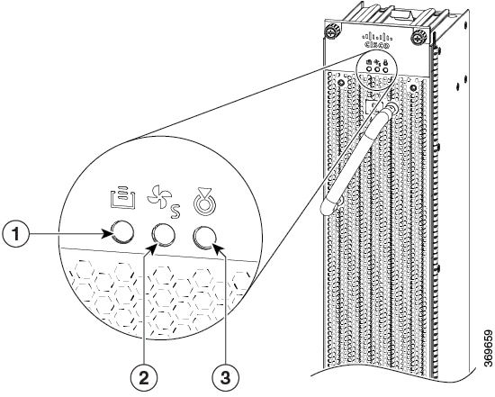
|
1 |
FC STS (Status) |
3 |
ATTN (Attention) |
|
2 |
FT STS (Status) |
|
LED |
Color |
Status |
|---|---|---|
|
ATTN (Attention)
|
Flashing Blue |
The operator has activated this LED to identify the fan tray in the chassis. |
|
Off |
The operator had not activated the LED to identify the fan tray in the chassis. |
|
|
FT STS |
Amber |
The fan tray is powered on. |
|
Green |
The fan tray is operational. |
|
|
Flashing amber |
The module has minor alarm. |
|
|
Flashing red |
The module has active major or critical alarms. |
|
|
Flashing green |
FPD upgrade in-progress. |
|
|
Off |
No power to the fan tray. |
|
|
FC STS |
Amber |
The fabric cards are powered on and is in one of the following states:
|
|
Green |
|
|
|
Off |
If both the fabric modules behind this fan tray are plugged out (or not present). |
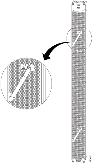
Every fan tray has a temperature warning label beside its handle. The temperature warning label is temperature sensitive. At normal operating temperatures (less than 55°C), the warning label has a black background with black edges. At temperatures above 55°C, the background color changes to white and the edges’ color changes to red.
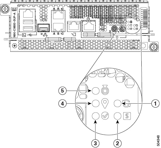
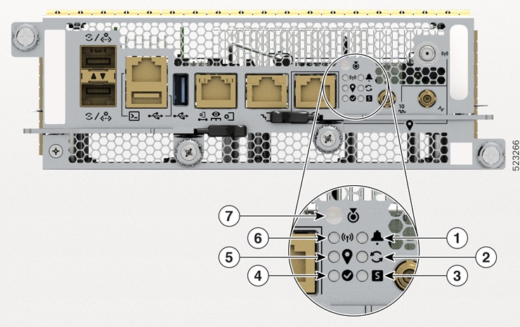
The Supervisor module LEDs are located on the front panel of the module.
|
1 |
SYNC |
4 |
GPS |
|
2 |
STS (Status) |
5 |
ATTN (Attention) |
|
3 |
Active |
|
1 |
Alarm |
5 |
GPS |
|
2 |
SYNC |
6 |
GNSS |
|
3 |
STS (Status) |
7 |
ATTN (Attention) |
|
4 |
Active |
- |
- |
|
LED |
Color |
Status |
|---|---|---|
|
ATTN (Attention)
|
Flashing blue |
The operator has activated this LED to identify this module in the chassis. |
|
Off |
This module is not being identified. |
|
|
Alarm  |
Flashing Red |
Chassis-wide Critical Alarm (on active RP) |
|
Flashing Amber |
Chassis-wide Major Alarm (on active RP) |
|
|
Solid Amber |
Chassis-wide Minor Alarm (on active RP) |
|
|
Off |
|
|
|
STS (Status)
|
Green |
This module is operational with no issues. |
|
Flashing green |
The auto or manual FPD upgrade in-progress. |
|
|
Flashing amber |
The module has minor alarm. |
|
|
Flashing red |
The module has active major or critical alarms. |
|
|
Amber |
The module is in one of the following states:
|
|
|
Red |
BIOS boot failure. Also, the ATTN LED remains blue. |
|
|
Off |
The module is not enabled. |
|
|
ACT (Active) |
Green |
The module is in the Active state. |
|
Off |
The module is in the Standby state. |
|
|
GPS
|
Green |
The GPS interface is provisioned and frequency, time of day and phase inputs are all operating correctly. |
|
Off |
The GPS interface is not provisioned, or the GPS inputs are not working correctly. |
|
|
GNSS  |
Green |
GNSS receiver interface is up. |
|
Off |
GNSS receiver interface could be
|
|
|
SYNC
|
Green |
The frequency, time, and phase are synchronized to an external interface. The external interface could be:
|
|
Amber |
The system is running in holdover or free-run mode and it is not synchronized to an external interface. |
|
|
Off |
The centralized frequency or time and phase distribution is not enabled. |
The fabric modules are located behind the fan trays.
 Note |
The fabric modules are located behind the fan tray. Therefore, the fabric module LEDs are seen when the fan tray is removed. |
|
LED |
Color |
Status |
|---|---|---|
|
ATTN (Attention)
|
Flashing blue |
The operator has activated this LED to identify this module in the chassis. |
|
Off |
This module is not being identified. |
|
|
STS
|
Green |
The fabric module is operational with no issues. |
|
Flashing green |
Auto or manual FPD upgrade in-progress. |
|
|
Amber |
The module is in one of the following states:
|
|
|
Flashing red |
The fabric module has major or critical alarms. |
|
|
Flashing amber |
The module has minor alarm. |
|
|
Off |
No power is going to the fabric card. |
The line card has LEDs located on the right of the front panel.
| LED | Color | Status |
|---|---|---|
|
ATTN (Attention)
|
Flashing blue |
The operator has activated this LED to identify this module in the chassis. |
|
Off |
The line card is not enabled. |
|
|
STS (Status)
|
Amber |
The module is in one of the following states:
|
|
Green |
This module is operational with no issues. |
|
|
Flashing green |
The auto or manual FPD upgrade in-progress. |
|
|
Flashing amber |
The module has a minor alarm. |
|
|
Flashing red |
The module has active major or critical alarms. |
|
|
Red |
BIOS boot failure. Also, the ATTN LED remains blue. |
|
|
Off |
The module is not enabled. |


 Feedback