Connect Switch to the Network
 Note |
The images in this chapter are only for representation purposes, unless specified otherwise. The chassis' actual appearance and size may vary. |
The documentation set for this product strives to use bias-free language. For the purposes of this documentation set, bias-free is defined as language that does not imply discrimination based on age, disability, gender, racial identity, ethnic identity, sexual orientation, socioeconomic status, and intersectionality. Exceptions may be present in the documentation due to language that is hardcoded in the user interfaces of the product software, language used based on RFP documentation, or language that is used by a referenced third-party product. Learn more about how Cisco is using Inclusive Language.
Note |
The images in this chapter are only for representation purposes, unless specified otherwise. The chassis' actual appearance and size may vary. |
Before you create a network management connection for the switch or connect the switch to the network, you must create a local management connection through a console terminal and configure an IP address for the switch. The switch can be accessed using remote management protocols, such as SSH and Telnet. By default, SSH is included in the software image. But telnet is not part of the software image. You must manually install the telnet optional package to use it.
You also can use the console to perform the following functions, each of which can be performed through the management interface after you make that connection:
configure the switch using the command-line interface (CLI)
monitor network statistics and errors
configure Simple Network Management Protocol (SNMP) agent parameters
initiate software download updates via console
You make this local management connection between the asynchronous serial port on a Supervisor module and a console device capable of asynchronous transmission. Typically, you can use a computer terminal as the console device. On the Supervisor module, you use the console serial port.
Note |
Before you can connect the console port to a computer terminal, make sure that the computer terminal supports VT100 terminal emulation. The terminal emulation software makes communication between the switch and computer possible during setup and configuration. |
The switch must be fully installed in its rack. The switch must be connected to a power source and grounded.
The necessary cabling for the console, management, and network connections must be available.
An RJ45 rollover cable and a DB9F/RJ45 adapter.
Network cabling should already be routed to the location of the installed switch.
|
Step 1 |
Configure the console device to match the following default port characteristics:
|
|
Step 2 |
Connect and RJ45 rollover cable to a terminal, PC terminal emulator, or terminal server. The RJ45 rollover cable is not part of the accessory kit. |
|
Step 3 |
Route the RJ45 rollover cable as appropriate and connect the cable to the console port on the chassis. If the console or modem cannot use an RJ45 connection, use the DB9F/RJ45F PC terminal adapter. Alternatively, you can use an RJ45/DSUB F/F or RJ45/DSUB R/P adapter, but you must provide those adapters. |
You are ready to create the initial switch configuration.
The Supervisor Module's management port (MGMT ETH) provides out-of-band management, which lets you to use the command-line interface (CLI) to manage the switch by its IP address. This port uses a 10/100/1000 Ethernet connection with an RJ-45 interface.
Note |
In a dual Supervisor Module switch, you can ensure that the active Supervisor Module is always connected to the network by connecting the management interface on both Supervisor Module to the network. That is, you can perform this task for each Supervisor Module. When the Supervisor Module is active, the switch automatically has a management interface that is running and accessible from the network. |
 Caution |
To prevent an IP address conflict, do not connect the MGMT 100/1000 Ethernet port until the initial configuration is complete. |
You must have completed the initial switch configuration.
|
Step 1 |
Connect a modular, RJ-45, UTP cable to the MGMT ETH port on the Supervisor Module. |
|
Step 2 |
Route the cable through the central slot in the cable management system. |
|
Step 3 |
Connect the other end of the cable to a 100/1000 Ethernet port on a network device. |
You are ready to connect the interface ports on each of the line cards to the network.
To determine which transceivers and cables are supported by this switch, see Cisco Transceiver Modules Compatibility Information.
To see the transceiver specifications and installation information, see Cisco Transceiver Modules Install and Upgrade Guides.
The RJ-45 connector connects Category 3, Category 5, Category 5e, Category 6, or Category 6A foil twisted-pair or unshielded twisted-pair cable from the external network to the following module interface connectors:
Switch chassis
CONSOLE port
MGMT ETH port
Caution |
To comply with GR-1089 intrabuilding, lightning immunity requirements, you must use a foil twisted-pair (FTP) cable that is properly grounded at both ends. |
The following figure shows the RJ-45 connector.

|
1 |
Pin 1 |
2 |
Pin 8 |
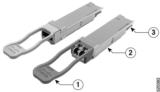
This section provides the installation, cabling, and removal instructions for the Quad Small Form-Factor Pluggable transceiver modules. Refer to the Cisco Optical Transceiver Handling Guide for additional details on optical transceivers.
The following figure shows a 400-Gigabit QSFP-DD optical transceiver.
|
1 |
Pull-tab |
2 |
QSFP-DD transceiver body |
|
3 |
Electrical connection to the module circuitry |
You need these tools to install the transceiver modules:
Wrist strap or other personal grounding device to prevent ESD occurrences.
Antistatic mat or antistatic foam to set the transceiver on.
Fiber-optic end-face cleaning tools and inspection equipment.
Caution |
The transceiver module is a static-sensitive device. Always use an ESD wrist strap or similar individual grounding device when handling transceiver modules or coming into contact with system modules. |
Caution |
Protect the transceiver ports by inserting clean dust caps (NXA-ACC-QDD-DC) into any ports not in use. Be sure to clean the optic surfaces of the fiber cables before you plug them back into the optical ports of another module. Use dust caps for all the open ports on the chassis. The switch ships with dust caps plugged in. We highly recommend you to keep the dust caps plugged in until you are ready to plug an optic. The dust caps protect the ports from possible EMI interference and also avoid contamination due to dust collection. To meet the EMI interference requirements, you must use the metal dust caps when the ports are not in use by optical modules. |
The QSFP transceiver module has a pull-tab latch. To install a transceiver module, follow these steps:
|
Step 1 |
Attach an ESD wrist strap to yourself and a properly grounded point on the chassis or the rack. |
||
|
Step 2 |
Remove the transceiver module from its protective packaging. |
||
|
Step 3 |
Check the label on the transceiver module body to verify that you have the correct model for your network. Do not remove the dust plug until you’re ready to attach the network interface cable. Dust plug is not shown in the images. |
||
|
Step 4 |
Hold the transceiver by the pull-tab so that the identifier label is on the top. |
||
|
Step 5 |
Align the transceiver module in front of the module’s transceiver socket opening and carefully slide the transceiver into the socket until the transceiver contact with the socket electrical connector. 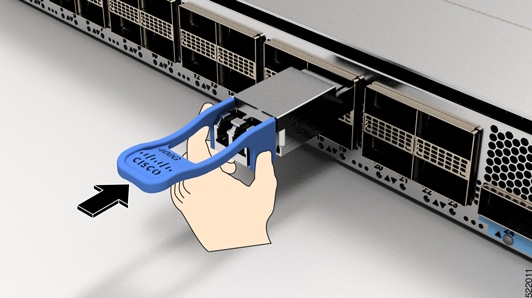
|
||
|
Step 6 |
Press firmly on the front of the transceiver module with your thumb to fully seat the transceiver in the module’s transceiver socket (see the below figure).
|
Before you remove the dust plugs and make any optical connections, follow these guidelines:
Keep the protective dust plugs installed in the unplugged fiber-optic cable connectors and in the transceiver optical bores until you are ready to make a connection.
Inspect and clean the optical connector end faces just before you make any connections.
Grasp the optical connector only by the housing to plug or unplug a fiber-optic cable.
Note |
The transceiver modules and fiber connectors are keyed to prevent incorrect insertion. |
Note |
The multiple-fiber push-on (MPO) connectors on the optical transceivers support network interface cables with either physical contact (PC) or ultra-physical contact (UPC) flat polished face types. The MPO connectors on the optical transceivers do not support network interface cables with an angle-polished contact (APC) face type. |
Note |
Inspect the MPO connector for the correct cable type, cleanliness, and any damage. For complete information on inspecting and cleaning fiber-optic connections, see the Inspection and Cleaning Procedures for Fiber-Optic Connections document. |
|
Step 1 |
Remove the dust plugs from the optical network interface cable MPO connectors and from the transceiver module optical bores. Save the dust plugs for future use. |
|
Step 2 |
Attach the network interface cable MPO connectors immediately to the transceiver module. 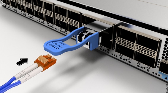 |
Caution |
The transceiver module is a static-sensitive device. Always use an ESD wrist strap or similar individual grounding device when handling transceiver modules or coming into contact with modules. |
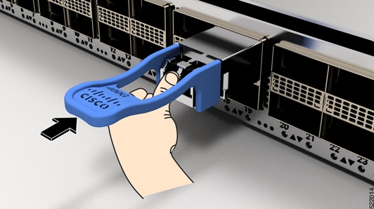
To remove a transceiver module, follow these steps:
|
Step 1 |
Disconnect the network interface cable from the transceiver connector. |
|
Step 2 |
Install the dust plug immediately into the transceiver’s optical bore. |
|
Step 3 |
Grasp the pull-tab and gently pull to release the transceiver from the socket.
|
|
Step 4 |
Slide the transceiver out of the socket. |
|
Step 5 |
Place the transceiver module into an antistatic bag. |
You can connect optical interface ports on line cards with other devices for network connectivity.
Depending on which line card model that you are using, you can use either QSFP-DD, QSFP28, or QSFP+ transceivers. Some transceivers work with fiber-optic cables that you attach to the transceivers and other transceivers work with pre-attached copper cables. You must install a transceiver in the port before installing the fiber-optic cable in the transceiver.
Caution |
Removing and installing a transceiver can shorten its useful life. Do not remove and insert transceivers any more than is absolutely necessary. We recommend that you disconnect cables before installing or removing transceivers to prevent damage to the cable or transceiver. |
When you need to remove fiber-optic transceivers, you must first remove the fiber-optic cables from the transceiver before you remove the transceiver from the port.
Refer to Inspection and Cleaning Procedures for Fiber-Optic Connections document for inspection and cleaning processes for fiber optic connections.
You must assign an IP address to the switch management interface to connect the switch to the network.
When you initially power up the switch, it boots up and asks a series of configuration-related questions. You can use the default choices for each configuration except for the IP address, which you must provide.
When the system is powered on and the console port is connected to the terminal, the RP CPU messages are seen. You can see RP CPU messages by pressing the hot-key sequence Ctrl-O.
A console device must be connected with the switch.
The switch must be connected to a power source.
Determine the IP address and netmask that is needed for the Management interfaces: MgmtEth0/RP0/CPU0/0
and MgmtEth0/RP1/CPU0/0:
|
Step 1 |
Power up the switch. The LEDs on each power supply light up (green) when the power supply units are sending power to the switch, and the software asks you to specify a password to use with the switch. |
||||
|
Step 2 |
When the system is booted up for the first time, a new username and a password is to be created. The following prompt appears: |
||||
|
Step 3 |
Enter a new password to use for this switch. The software checks the security strength of your password and rejects your password if it is not considered to be a strong password. To increase the security strength of your password, make sure that it adheres to the following guidelines:
When you enter a strong password, the software asks you to confirm the password. |
||||
|
Step 4 |
Reenter the password. When you enter the same password, the software accepts the password. |
||||
|
Step 5 |
Enter the configuration mode. |
||||
|
Step 6 |
Enter the IP address for the management interface. If using dual RPs, enter the IP address on both management interfaces. |
||||
|
Step 7 |
Enter a network mask for the management interface. |
||||
|
Step 8 |
The software asks whether you want to edit the configuration. Enter 'no' to decline. |
After installing the chassis, use the following show commands to verify the installation and configuration in the EXEC mode. Any issue if detected, take corrective action before making further configurations.
|
Command |
Description |
||
|---|---|---|---|
|
show module |
Displays the state information of each card. |
||
|
show redundancy |
Displays the status of supervisor module redundancy. |
||
|
n9k-184-Man(config)# show locator-led st |
Displays LED information for the switch, or for a specific LED location. |
||
|
show inventory |
Displays information about the field replaceable units (FRUs), including product IDs, serial numbers, and version IDs. |
||
|
show environment |
|
||
|
show environment temperature |
Displays temperature readings for card temperature sensors. Each Supervisor Module, line card, and fabric cards have temperature sensors with two thresholds:
|
||
|
show environment power |
Displays the power usage information for the entire switch. |
||
|
show environment current |
Displays the current environment status. |
||
|
show environment fan |
Displays the status of the fan trays. |
The following example shows sample output from the show environment command for 9800 switches:
n9k-184-Man(config)# show environment
Fan:
---------------------------------------------------------------------------
Fan Model Hw Direction Status
---------------------------------------------------------------------------
Fan1(sys_fan1) N9K-C980x-FAN-A 1.0 front-to-back Ok
Fan2(sys_fan2) N9K-C980x-FAN-A 1.0 front-to-back Ok
Fan3(sys_fan3) N9K-C980x-FAN-A 1.0 front-to-back Ok
Fan4(sys_fan4) N9K-C980x-FAN-A 1.0 front-to-back Ok
Fan_in_PS1 -- front-to-back Absent
Fan_in_PS2 -- front-to-back Absent
Fan_in_PS3 -- front-to-back Absent
Fan_in_PS4 -- front-to-back Shutdown
Fan_in_PS5 -- front-to-back Ok
Fan_in_PS6 -- front-to-back Ok
Fan_in_PS7 -- front-to-back Ok
Fan_in_PS8 -- front-to-back Shutdown
Fan_in_PS9 -- front-to-back Ok
Fan Zone Speed: Zone 1: 0x80
Fan Air Filter : NotSupported


Power Supply:
Voltage: 54 Volts
Power Actual Actual Total
Supply Model Output Input Capacity Status
(Watts ) (Watts ) (Watts )
------- ---------- --------------- ------ ---------- --------------------
1 ------------ 0 W 0 W 0 W Absent
2 ------------ 0 W 0 W 0 W Absent
3 ------------ 0 W 0 W 0 W Absent
4 PSU6.3KW-20A-HV 0 W 0 W 0 W Shutdown
5 PSU6.3KW-20A-HV 992 W 1048 W 3150 W Ok
6 PSU6.3KW-20A-HV 964 W 1024 W 3150 W Ok
7 PSU6.3KW-20A-HV 964 W 1024 W 3150 W Ok
8 PSU6.3KW-20A-HV 0 W 0 W 0 W Shutdown
9 PSU6.3KW-20A-HV 981 W 1045 W 3150 W Ok


Actual Power
Module Model Draw Allocated Status
(Watts ) (Watts )
------- ------------------- ----------- ----------- --------------
1 N9K-X9836DM-A 771.00 W 2435.94 W Powered-Up
5 N9K-X9836DM-A 1046.00 W 2435.94 W Powered-Up
8 N9K-X9836DM-A 776.00 W 2435.94 W Powered-Up
Xb19 N9K-C980x-FM-A 233.00 W 574.56 W Powered-Up
Xb20 N9K-C980x-FM-A 238.00 W 574.56 W Powered-Up
Xb21 xbar N/A 0.00 W Absent
Xb22 xbar N/A 0.00 W Absent
Xb23 xbar N/A 0.00 W Absent
Xb24 xbar N/A 0.00 W Absent
Xb25 xbar N/A 0.00 W Absent
Xb26 xbar N/A 0.00 W Absent
27 N9K-C9800-SUP-A 80.00 W 94.50 W Powered-Up
28 supervisor N/A 94.50 W Absent
fan1 N9K-C980x-FAN-A 170.00 W 686.00 W Powered-Up
fan2 N9K-C980x-FAN-A 187.00 W 686.00 W Powered-Up
fan3 N9K-C980x-FAN-A 176.00 W 686.00 W Powered-Up
fan4 N9K-C980x-FAN-A 175.00 W 686.00 W Powered-Up

N/A - Per module power not available


Power Usage Summary:
--------------------
Power Supply redundancy mode (configured) Non-Redundant(combined)
Power Supply redundancy mode (operational) Non-Redundant(combined)

Total Power Capacity (based on configured mode) 12599.00 W
Total Power of all Inputs (cumulative) 12599.00 W
Total Power Output (actual draw) 3901.00 W
Total Power Input (actual draw) 4141.00 W
Total Power Allocated (budget) 11393.00 W
Total Power Available for additional modules 1206.28 W


Temperature:
--------------------------------------------------------------------
Module Sensor MajorThresh MinorThres CurTemp Status
(Celsius) (Celsius) (Celsius)
--------------------------------------------------------------------
1 CPU 100 98 65 Ok
1 Sone-1 110 100 46 Ok
1 Sone-2 110 100 48 Ok
1 Sone-3 110 100 50 Ok
5 CPU 100 98 79 Ok
5 Sone-1 110 100 71 Ok
5 Sone-2 110 100 69 Ok
5 Sone-3 110 100 65 Ok
8 CPU 100 98 63 Ok
8 Sone-1 110 100 50 Ok
8 Sone-2 110 100 50 Ok
8 Sone-3 110 100 48 Ok
19 Sone-1 110 100 34 Ok
19 Sone-2 110 100 39 Ok
20 Sone-1 110 100 35 Ok
20 Sone-2 110 100 43 Ok
27 OUTLET 85 80 26 Ok
27 INLET 45 42 22 Ok
27 CPU 97 93 44 Ok
The following example displays the temperature readings for each of the powered-up cards using the show environment temperatures command:
9k-184-Man(config)# show environment temperature
Temperature:
--------------------------------------------------------------------
Module Sensor MajorThresh MinorThres CurTemp Status
(Celsius) (Celsius) (Celsius)
--------------------------------------------------------------------
1 CPU 100 98 65 Ok
1 Sone-1 110 100 46 Ok
1 Sone-2 110 100 48 Ok
1 Sone-3 110 100 50 Ok
5 CPU 100 98 80 Ok
5 Sone-1 110 100 71 Ok
5 Sone-2 110 100 68 Ok
5 Sone-3 110 100 65 Ok
8 CPU 100 98 63 Ok
8 Sone-1 110 100 50 Ok
8 Sone-2 110 100 50 Ok
8 Sone-3 110 100 48 Ok
19 Sone-1 110 100 34 Ok
19 Sone-2 110 100 39 Ok
20 Sone-1 110 100 35 Ok
20 Sone-2 110 100 42 Ok
27 OUTLET 85 80 26 Ok
27 INLET 45 42 22 Ok
27 CPU 97 93 43 Ok
n9k-184-Man(config)#
The following example shows sample output from the show environment power command:
n9k-184-Man(config)# show environment power
Power Supply:
Voltage: 54 Volts
Power Actual Actual Total
Supply Model Output Input Capacity Status
(Watts ) (Watts ) (Watts )
------- ---------- --------------- ------ ---------- --------------------
1 ------------ 0 W 0 W 0 W Absent
2 ------------ 0 W 0 W 0 W Absent
3 ------------ 0 W 0 W 0 W Absent
4 PSU6.3KW-20A-HV 0 W 0 W 0 W Shutdown
5 PSU6.3KW-20A-HV 992 W 1048 W 3150 W Ok
6 PSU6.3KW-20A-HV 967 W 1024 W 3150 W Ok
7 PSU6.3KW-20A-HV 964 W 1024 W 3150 W Ok
8 PSU6.3KW-20A-HV 0 W 0 W 0 W Shutdown
9 PSU6.3KW-20A-HV 978 W 1045 W 3150 W Ok


Actual Power
Module Model Draw Allocated Status
(Watts ) (Watts )
------- ------------------- ----------- ----------- --------------
1 N9K-X9836DM-A 771.00 W 2435.94 W Powered-Up
5 N9K-X9836DM-A 1046.00 W 2435.94 W Powered-Up
8 N9K-X9836DM-A 775.00 W 2435.94 W Powered-Up
Xb19 N9K-C980x-FM-A 233.00 W 574.56 W Powered-Up
Xb20 N9K-C980x-FM-A 238.00 W 574.56 W Powered-Up
Xb21 xbar N/A 0.00 W Absent
Xb22 xbar N/A 0.00 W Absent
Xb23 xbar N/A 0.00 W Absent
Xb24 xbar N/A 0.00 W Absent
Xb25 xbar N/A 0.00 W Absent
Xb26 xbar N/A 0.00 W Absent
27 N9K-C9800-SUP-A 87.00 W 94.50 W Powered-Up
28 supervisor N/A 94.50 W Absent
fan1 N9K-C980x-FAN-A 198.00 W 686.00 W Powered-Up
fan2 N9K-C980x-FAN-A 184.00 W 686.00 W Powered-Up
fan3 N9K-C980x-FAN-A 173.00 W 686.00 W Powered-Up
fan4 N9K-C980x-FAN-A 189.00 W 686.00 W Powered-Up

N/A - Per module power not available


Power Usage Summary:
--------------------
Power Supply redundancy mode (configured) Non-Redundant(combined)
Power Supply redundancy mode (operational) Non-Redundant(combined)

Total Power Capacity (based on configured mode) 12599.00 W
Total Power of all Inputs (cumulative) 12599.00 W
Total Power Output (actual draw) 3901.00 W
Total Power Input (actual draw) 4141.00 W
Total Power Allocated (budget) 11393.00 W
Total Power Available for additional modules 1206.28 W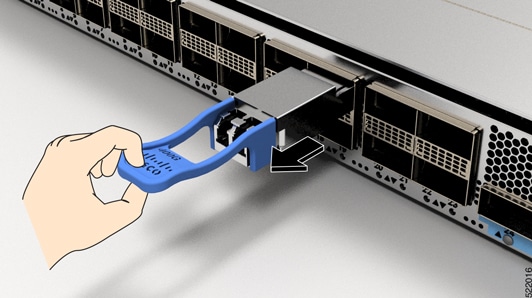
 Feedback