Configuring Virtual Port Channels
Available Languages
Contents
- Configuring Virtual Port Channels
- Information About vPCs
- vPC Overview
- vPC Terminology
- Fabric Extender Terminology
- Cisco Nexus 5000 Series Switch vPC Topology
- Single Homed Fabric Extender vPC Topology
- Dual Homed Fabric Extender vPC Topology
- vPC Domain
- Peer-Keepalive Link and Messages
- Compatibility Parameters for vPC Peer Links
- Configuration Parameters That Must Be Identical
- Configuration Parameters That Should Be Identical
- Graceful Type-1 Check
- Per-VLAN Consistency Check
- vPC Auto-Recovery
- vPC Peer Links
- vPC Peer Link Overview
- vPC Number
- vPC and LACP
- vPC Peer Links and STP
- CFSoE
- vPC Guidelines and Limitations
- Configuring vPCs
- Enabling vPCs
- Disabling vPCs
- Creating a vPC Domain
- Configuring a vPC Keepalive Link and Messages
- Configuring a Keepalive Link When Using a Front-Panel 10-Gigabit Ethernet Port
- Creating a vPC Peer Link
- Checking the Configuration Compatibility
- Enabling vPC Auto-Recovery
- Configuring the Restore Time Delay
- Excluding VLAN Interfaces From Shutdown When vPC Peer Link Fails
- Configuring the VRF Name
- Binding a VRF Instance to a vPC
- Enabling Layer 3 Forwarding to the Gateway MAC Address of the vPC
- Suspending Orphan Ports on a Secondary Switch in a vPC Topology
- Creating an EtherChannel Host Interface
- Moving Other EtherChannels into a vPC
- Manually Configuring a vPC Domain MAC Address
- Manually Configuring the System Priority
- Manually Configuring a vPC Peer Switch Role
- Verifying the vPC Configuration
- Viewing The Graceful Type-1 Check Status
- Viewing A Global Type-1 Inconsistency
- Viewing An Interface-Specific Type-1 Inconsistency
- Viewing a Per-VLAN Consistency Status
- vPC Example Configurations
- Dual Homed Fabric Extender vPC Configuration Example
- Single Homed Fabric Extender vPC Configuration Example
- vPC Default Settings
Configuring Virtual Port Channels
This chapter describes how to configure virtual port channels (vPCs) on Cisco Nexus 5000 Series switches. It contains the following sections:
- Information About vPCs
- vPC Guidelines and Limitations
- Configuring vPCs
- Verifying the vPC Configuration
- vPC Example Configurations
- vPC Default Settings
vPC Overview
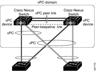
A virtual port channel (vPC) allows links that are physically connected to two different Cisco Nexus 5000 Series switches or Cisco Nexus 2000 Series Fabric Extenders to appear as a single port channel by a third device (see the following figure). The third device can be a switch, server, or any other networking device. Beginning with Cisco NX-OS Release 4.1(3)N1(1), you can configure vPCs in topologies that include Cisco Nexus 5000 Series switches connected to the Fabric Extender. A vPC can provide multipathing, which allows you to create redundancy by enabling multiple parallel paths between nodes and load balancing traffic where alternative paths exist.
You configure the EtherChannels by using one of the following:
When you configure the EtherChannels in a vPC—including the vPC peer link channel—each switch can have up to 16 active links in a single EtherChannel. When you configure a vPC on a Fabric Extender, only one port is allowed in an EtherChannel.
Note
You must enable the vPC feature before you can configure or run the vPC functionality.
To enable the vPC functionality, you must create a peer-keepalive link and a peer-link under the vPC domain for the two vPC peer switches to provide the vPC functionality.
To create a vPC peer link you configure an EtherChannel on one Cisco Nexus 5000 Series switch by using two or more Ethernet ports. On the other switch, you configure another EtherChannel again using two or more Ethernet ports. Connecting these two EtherChannels together creates a vPC peer link.
Note
We recommend that you configure the vPC peer-link EtherChannels as trunks.
The vPC domain includes both vPC peer devices, the vPC peer-keepalive link, the vPC peer link, and all of the EtherChannels in the vPC domain connected to the downstream device. You can have only one vPC domain ID on each vPC peer device.
Note
Always attach all vPC devices using EtherChannels to both vPC peer devices.
A vPC provides the following benefits:
- Allows a single device to use an EtherChannel across two upstream devices
- Eliminates Spanning Tree Protocol (STP) blocked ports
- Provides a loop-free topology
- Uses all available uplink bandwidth
- Provides fast convergence if either the link or a switch fails
- Provides link-level resiliency
- Assures high availability
vPC Terminology
The terminology used in vPCs is as follows:
vPC—The combined EtherChannel between the vPC peer devices and the downstream device.
vPC peer device—One of a pair of devices that are connected with the special EtherChannel known as the vPC peer link.
vPC peer link—The link used to synchronize states between the vPC peer devices.
vPC member port—Interfaces that belong to the vPCs.
Host vPC port—Fabric Extender host interfaces that belong to a vPC.
vPC domain—This domain includes both vPC peer devices, the vPC peer-keepalive link, and all of the port channels in the vPC connected to the downstream devices. It is also associated to the configuration mode that you must use to assign vPC global parameters. The vPC domain ID must be the same on both switches.
vPC peer-keepalive link—The peer-keepalive link monitors the vitality of a vPC peer Cisco Nexus 5000 Series device. The peer-keepalive link sends configurable, periodic keepalive messages between vPC peer devices.
No data or synchronization traffic moves over the vPC peer-keepalive link; the only traffic on this link is a message that indicates that the originating switch is operating and running vPCs.
Fabric Extender Terminology
The terminology used for the Cisco Nexus 2000 Series Fabric Extender is as follows:
Fabric interface—A 10-Gigabit Ethernet uplink port designated for connection from the Fabric Extender to its parent switch. A fabric interface cannot be used for any other purpose. It must be directly connected to the parent switch.
EtherChannel fabric interface—An EtherChannel uplink connection from the Fabric Extender to its parent switch. This connection consists of fabric interfaces bundled into a single logical channel.
Host interface—An Ethernet interface for server or host connectivity. These ports are 1-Gigabit Ethernet interfaces or 10-Gigabit Ethernet interfaces, depending on the fabric extender model.
EtherChannel host interface—An EtherChannel downlink connection from the Fabric Extender host interface to a server port.
Note
In Release 4.1(3)N1(1), an EtherChannel host interface consists of only one host interface and can be configured either as a Link Aggregation Control Protocol (LACP) or non-LACP EtherChannel.
For further information about the Fabric Extender, refer to the Cisco Nexus 2000 Series Fabric Extender Software Configuration Guide.
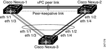
Cisco Nexus 5000 Series Switch vPC Topology
You can connect a pair of Cisco Nexus 5000 Series switches or a pair of Cisco Nexus 5500 Series switches in a vPC directly to another switch or to a server. vPC peer switches must be of the same type, for example, you can connect a pair of Nexus 5000 series switches or a pair of Nexus 5500 Series switches but you cannot connect a Nexus 5000 Series switch to a Nexus 5500 Series switch in a vPC topology. Up to 8 interfaces could be connected to each Cisco Nexus 5000 Series switch providing 16 interfaces bundled for the vPC pair. The topology that is shown in the following figure provides the vPC functionality to dual connected switches or servers with 10-Gigabit or 1-Gigabit Ethernet uplink interfaces.
Note
The first 8 ports on the Cisco Nexus 5010 switch and the first 16 ports on the Cisco Nexus 5020 switch are switchable 1-Gigabit and 10-Gigabit ports. You can enable vPC functionality on these ports in 1-Gigabit mode.
The switch connected to the pair of Cisco Nexus 5000 Series switches can be any standards-based Ethernet switch. Common environments to use this configuration include Blade Chassis with dual switches connected to the pair of Cisco Nexus 5000 Series switches through vPC or Unified Computing Systems connected to the pair of Cisco Nexus 5000 Series switches.
Single Homed Fabric Extender vPC Topology
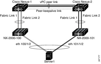
You can connect a server with dual or quad or more network adapters that are configured in a vPC to a pair of Cisco Nexus 2000 Series Fabric Extenders which are connected to the Cisco Nexus 5000 Series switches as depicted. Depending on the FEX model, you may be able to connect one or more network adapter interfaces to each fabric extender. As an example, Figure 10 refers to a topology built with the Cisco Nexus 2148T fabric extender, where a server has one link only to each fabric extender. A topology with Cisco Nexus 2248TP or with Cisco Nexus 2232PP fabric extender could consist of more links from the server to a single fabric extender.
. The topology that is shown in the following figure provides the vPC functionality to dual homed servers with 1-Gigabit Ethernet uplink interfaces.
The Cisco Nexus 5000 Series switch can support up to 12 configured single homed Fabric Extenders (576 ports) with this topology however only 480 576 dual homed host servers can be configured in a vPCs with this configuration.
Note
The Cisco Nexus 2148T fabric extender does not support EtherChannels on its host interfaces. Therefore a maximum of two links can be configured in an EtherChannel from the server where each link is connected to a separate Fabric Extender.
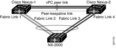
Dual Homed Fabric Extender vPC Topology
You can connect the Cisco Nexus 2000 Series Fabric Extender to two upstream Cisco Nexus 5000 Series switches and downstream to a number of single homed servers. The topology shown in the following figure provides the vPC functionality to singly connected servers with 1-Gigabit Ethernet uplink interfaces.
The Cisco Nexus 5000 Series switch can support up to 12 configured dual homed Fabric Extenders with this topology. A maximum of 576 single homed servers can be connected to this configuration.
vPC Domain
To create a vPC domain, you must first create a vPC domain ID on each vPC peer switch using a number from 1 to 1000. This ID must be the same on a set of vPC peer devices.
You can configure the EtherChannels and vPC peer links by using LACP or no protocol. When possible, we recommend that you use LACP on the peer-link, because LACP provides configuration checks against a configuration mismatch on the etherchannel.
The vPC peer switches use the vPC domain ID that you configure to automatically assign a unique vPC system MAC address. Each vPC domain has a unique MAC address that is used as a unique identifier for the specific vPC-related operations, although the switches use the vPC system MAC addresses only for link-scope operations, such as LACP. We recommend that you create each vPC domain within the contiguous network with a unique domain ID. You can also configure a specific MAC address for the vPC domain, rather than having the Cisco NX-OS software assign the address.
The vPC peer switches use the vPC domain ID that you configure to automatically assign a unique vPC system MAC address. The switches use the vPC system MAC addresses only for link-scope operations, such as LACP or BPDUs. You can also configure a specific MAC address for the vPC domain.
After you create a vPC domain, the Cisco NX-OS software automatically creates a system priority for the vPC domain. You can also manually configure a specific system priority for the vPC domain.
Note
If you manually configure the system priority, you must ensure that you assign the same priority value on both vPC peer switches. If the vPC peer switches have different system priority values, the vPC will not come up.
Peer-Keepalive Link and Messages
The Cisco NX-OS software uses a peer-keepalive link between the vPC peers to transmit periodic, configurable keepalive messages. You must have Layer 3 connectivity between the peer switches to transmit these messages; the system cannot bring up the vPC peer link unless a peer-keepalive link is already up and running.
If one of the vPC peer switches fails, the vPC peer switch on the other side of the vPC peer link senses the failure when it does not receive any peer-keepalive messages. The default interval time for the vPC peer-keepalive message is 1 second. You can configure the interval between 400 milliseconds and 10 seconds. You can also configure a timeout value with a range of 3 to 20 seconds; the default timeout value is 5 seconds. The peer-keepalive status is checked only when the peer-link goes down.
The vPC peer-keepalive can be carried either in the management or default VRF on the Cisco Nexus 5000 Series switch. When you configure the switches to use the management VRF, the source and destination for the keepalive messages are the mgmt 0 interface IP addresses. When you configure the switches to use the default VRF, an SVI must be created to act as the source and destination addresses for the vPC peer-keepalive messages. Ensure that both the source and destination IP addresses used for the peer-keepalive messages are unique in your network and these IP addresses are reachable from the VRF associated with the vPC peer-keepalive link.
Note
We recommend that you configure the vPC peer-keepalive link on the Cisco Nexus 5000 Series switch to run in the management VRF using the mgmt 0 interfaces. If you configure the default VRF, ensure that the vPC peer link is not used to carry the vPC peer-keepalive messages.
Compatibility Parameters for vPC Peer Links
Many configuration and operational parameters must be identical on all interfaces in the vPC. After you enable the vPC feature and configure the peer link on both vPC peer switches, Cisco Fabric Services (CFS) messages provide a copy of the configuration on the local vPC peer switch configuration to the remote vPC peer switch. The system then determines whether any of the crucial configuration parameters differ on the two switches.
Enter the show vpc consistency-parameters command to display the configured values on all interfaces in the vPC. The displayed configurations are only those configurations that would limit the vPC peer link and vPC from coming up.
The compatibility check process for vPCs differs from the compatibility check for regular EtherChannels.
Configuration Parameters That Must Be Identical
The configuration parameters in this section must be configured identically on both switches at either end of the vPC peer link.
Note
You must ensure that all interfaces in the vPC have the identical operational and configuration parameters listed in this section.
Enter the show vpc consistency-parameters command to display the configured values on all interfaces in the vPC. The displayed configurations are only those configurations that would limit the vPC peer link and vPC from coming up.
The switch automatically check for compatibility of these parameters on the vPC interfaces. The per-interface parameters must be consistent per interface, and the global parameters must be consistent globally.
- Port-channel mode: on, off, or active
- Link speed per channel
- Duplex mode per channel
- Trunk mode per channel:
- Spanning Tree Protocol (STP) mode
- STP region configuration for Multiple Spanning Tree (MST)
- Enable or disable state per VLAN
- STP global settings:
- STP interface settings:
- For the Fabric Extender vPC topology, all the interface level parameters mentioned above should be identically configured for host interface from both the switches.
- Fabric Extender FEX number configured on an EtherChannel fabric interface; for the Fabric Extender vPC toplogy.
If any of these parameters are not enabled or defined on either switch, the vPC consistency check ignores those parameters.
Note
To ensure that none of the vPC interfaces are in the suspend mode, enter the show vpc brief and show vpc consistency-parameters commands and check the syslog messages.
Configuration Parameters That Should Be Identical
When any of the following parameters are not configured identically on both vPC peer switches, a misconfiguration may cause undesirable behavior in the traffic flow:
- MAC aging timers
- Static MAC entries
- VLAN interface—Each switch on the end of the vPC peer link must have a VLAN interface configured for the same VLAN on both ends and they must be in the same administrative and operational mode. Those VLANs configured on only one switch of the peer link do not pass traffic using the vPC or peer link. You must create all VLANs on both the primary and secondary vPC switches, or the VLAN will be suspended.
- Private VLAN configuration
- All ACL configurations and parameters
- Quality of service (QoS) configuration and parameters—Local parameters; global parameters must be identical
- STP interface settings:
To ensure that all the configuration parameters are compatible, we recommend that you display the configurations for each vPC peer switch once you configure the vPC.
Graceful Type-1 Check
Beginning with Cisco NX--OS Release 5.0(2)N2(1), when a consistency check fails, vPCs are brought down only on the secondary vPC switch. The VLANs remain up on the primary switch and Type-1 configurations can be performed without traffic disruption. This feature is used both in the case of global as well as interface-specific Type-1 inconsistencies.
This feature is not enabled for dual-active FEX ports. When a Type-1 mismatch occurs, VLANs are suspended on these ports on both switches.
Per-VLAN Consistency Check
Beginning with Ciscon NX-OS Release 5.0(2)N2(1), some Type-1 consistency checks are performed on a per-VLAN basis for when spanning tree is enabled or disabled on a VLAN. VLANs that do not pass the consistency check are brought down on both the primary and secondary switches while other VLANs are not affected.
vPC Auto-Recovery
Beginning with Cisco NX-OS Release 5.0(2)N2(1), the vPC auto-recovery feature re-enables vPC links in the following scenarios:
When both vPC peer switches reload and only one switch reboots, auto-recovery allows that switch to assume the role of the primary switch and the vPC links will be allowed to come up after a predetermined period of time. The reload delay period in this scenario can range from 240-3600 seconds.
When vPCs are disabled on a secondary vPC switch due to a peer-link failure and then the primary vPC switch fails or is unable to forward traffic, the secondary switch re-enables the vPCs. In this scenario, the vPC waits for three consecutive keep-alive failures to recover the vPC links.
The vPC auto-recovery feature is disabled by default.
vPC Peer Links
vPC Peer Link Overview
You can have only two switches as vPC peers; each switch can serve as a vPC peer to only one other vPC peer. The vPC peer switches can also have non-vPC links to other switches.
To make a valid configuration, you configure an EtherChannel on each switch and then configure the vPC domain. You assign the EtherChannel on each switch as a peer link. For redundancy, we recommend that you should configure at least two dedicated ports into the EtherChannel; if one of the interfaces in the vPC peer link fails, the switch automatically falls back to use another interface in the peer link.
Note
We recommend that you configure the EtherChannels in trunk mode.
Many operational parameters and configuration parameters must be the same in each switch connected by a vPC peer link. Because each switch is completely independent on the management plane, you must ensure that the switches are compatible on the critical parameters. vPC peer switches have separate control planes. After configuring the vPC peer link, you should display the configuration on each vPC peer switch to ensure that the configurations are compatible.
Note
You must ensure that the two switches connected by the vPC peer link have certain identical operational and configuration parameters.
When you configure the vPC peer link, the vPC peer switches negotiate that one of the connected switches is the primary switch and the other connected switch is the secondary switch. By default, the Cisco NX-OS software uses the lowest MAC address to elect the primary switch. The software takes different actions on each switch—that is, the primary and secondary—only in certain failover conditions. If the primary switch fails, the secondary switch becomes the operational primary switch when the system recovers, and the previously primary switch is now the secondary switch.
You can also configure which of the vPC switches is the primary switch. If you want to configure the role priority again to make one vPC switch the primary switch, configure the role priority on both the primary and secondary vPC switches with the appropriate values, shut down the EtherChannel that is the vPC peer link on both switches by entering the shutdown command, and reenable the EtherChannel on both switches by entering the no shutdown command.
MAC addresses that are learned over vPC links are also synchronized between the peers.
Configuration information flows across the vPC peer links using the Cisco Fabric Services over Ethernet (CFSoE) protocol. All MAC addresses for those VLANs configured on both switches are synchronized between vPC peer switches. The software uses CFSoE for this synchronization.
If the vPC peer link fails, the software checks the status of the remote vPC peer switch using the peer-keepalive link, which is a link between vPC peer switches, to ensure that both switches are up. If the vPC peer switch is up, the secondary vPC switch disables all vPC ports on its switch. The data then forwards down the remaining active links of the EtherChannel.
The software learns of a vPC peer switch failure when the keepalive messages are not returned over the peer-keepalive link.
Use a separate link (vPC peer-keepalive link) to send configurable keepalive messages between the vPC peer switches. The keepalive messages on the vPC peer-keepalive link determines whether a failure is on the vPC peer link only or on the vPC peer switch. The keepalive messages are used only when all the links in the peer link fail.
vPC Number
Once you have created the vPC domain ID and the vPC peer link, you can create EtherChannels to attach the downstream switch to each vPC peer switch. That is, you create one single EtherChannel on the downstream switch with half of the ports to the primary vPC peer switch and the other half of the ports to the secondary peer switch.
On each vPC peer switch, you assign the same vPC number to the EtherChannel that connects to the downstream switch. You will experience minimal traffic disruption when you are creating vPCs. To simplify the configuration, you can assign the vPC ID number for each EtherChannel to be the same as the EtherChannel itself (that is, vPC ID 10 for EtherChannel 10).
Note
The vPC number that you assign to the EtherChannel connecting to the downstream switch from the vPC peer switch must be identical on both vPC peer switches.
vPC and LACP
The Link Aggregation Control Protocol (LACP) uses the system MAC address of the vPC domain to form the LACP Aggregation Group (LAG) ID for the vPC.
You can use LACP on all the vPC EtherChannels, including those channels from the downstream switch. We recommend that you configure LACP with active mode on the interfaces on each EtherChannel on the vPC peer switches. This configuration allows you to more easily detect compatibility between switches, unidirectional links, and multihop connections, and provides dynamic reaction to run-time changes and link failures.
The vPC peer link supports 16 EtherChannel interfaces.
Note
When manually configuring the system priority, you must ensure that you assign the same priority value on both vPC peer switches. If the vPC peer switches have different system priority values, vPC will not come up.
vPC Peer Links and STP
When you first bring up the vPC functionality, STP reconverges. STP treats the vPC peer link as a special link and always includes the vPC peer link in the STP active topology.
We recommend that you set all the vPC peer link interfaces to the STP network port type so that Bridge Assurance is automatically enabled on all vPC peer links. We also recommend that you do not enable any of the STP enhancement features on VPC peer links.
You must configure a list of parameters to be identical on the vPC peer switches on both sides of the vPC peer link.
STP is distributed; that is, the protocol continues running on both vPC peer switches. However, the configuration on the vPC peer switch elected as the primary switch controls the STP process for the vPC interfaces on the secondary vPC peer switch.
The primary vPC switch synchronizes the STP state on the vPC secondary peer switch using Cisco Fabric Services over Ethernet (CFSoE).
The vPC manager performs a proposal/handshake agreement between the vPC peer switches that sets the primary and secondary switches and coordinates the two switches for STP. The primary vPC peer switch then controls the STP protocol for vPC interfaces on both the primary and secondary switches.
The Bridge Protocol Data Units (BPDUs) use the MAC address set for the vPC for the STP bridge ID in the designated bridge ID field. The vPC primary switch sends these BPDUs on the vPC interfaces.
Note
Display the configuration on both sides of the vPC peer link to ensure that the settings are identical. Use the show spanning-tree command to display information about the vPC.
CFSoE
The Cisco Fabric Services over Ethernet (CFSoE) is a reliable state transport mechanism that you can use to synchronize the actions of the vPC peer devices. CFSoE carries messages and packets for many features linked with vPC, such as STP and IGMP. Information is carried in CFS/CFSoE protocol data units (PDUs).
When you enable the vPC feature, the device automatically enables CFSoE, and you do not have to configure anything. CFSoE distributions for vPCs do not need the capabilities to distribute over IP or the CFS regions. You do not need to configure anything for the CFSoE feature to work correctly on vPCs.
You can use the show mac address-table command to display the MAC addresses that CFSoE synchronizes for the vPC peer link.
Note
Do not enter the no cfs eth distribute or the no cfs distribute command. CFSoE must be enabled for vPC functionality. If you do enter either of these commands when vPC is enabled, the system displays an error message.
When you enter the show cfs application command, the output displays "Physical-eth," which shows the applications that are using CFSoE.
vPC Guidelines and Limitations
vPC has the following configuration guidelines and limitations:
You must enable the vPC feature before you can configure vPC peer-link and vPC interfaces.
You must configure the peer-keepalive link before the system can form the vPC peer link.
You can connect a pair of Cisco Nexus 5000 Series switches or a pair of Cisco Nexus 5500 Series switches in a vPC directly to another switch or to a server. vPC peer switches must be of the same type, for example, you can connect a pair of Nexus 5000 series switches or a pair of Nexus 5500 Series switches but you cannot connect a Nexus 5000 Series switch to a Nexus 5500 Series switch in a vPC topology.
Only EtherChannels can be in vPCs. A vPC can be configured on a normal EtherChannel (switch-to-switch vPC topology), on an EtherChannel fabric interface (fabric extender vPC topology), and on an EtherChannel host interface (host interface vPC topology).
Note
Refer to the Cisco Nexus 2000 Series Fabric Extender Software Configuration Guide for information about Fabric Extender host and fabric interfaces.
A Fabric Extender can be a member of a Host Interface vPC topology or a Fabric Extender vPC topology but not both simultaneously.
You must configure both vPC peer switches; the configuration is not automatically synchronized between the vPC peer devices.
Check that the necessary configuration parameters are compatible on both sides of the vPC peer link.
You may experience minimal traffic disruption while configuring vPCs.
You should configure all the EtherChannels in the vPC using LACP with the interfaces in active mode.
Enabling vPCs
SUMMARY STEPS2. switch(config)# feature vpc
3. (Optional) switch# show feature
4. (Optional) switch# copy running-config startup-config
DETAILED STEPS
Command or Action Purpose Step 1 switch# configure terminal
Enters configuration mode.
Step 2 switch(config)# feature vpc
Enables vPCs on the switch.
Step 3 switch# show feature
(Optional) Displays which features are enabled on the switch.
Step 4 switch# copy running-config startup-config
(Optional) Copies the running configuration to the startup configuration.
Disabling vPCs
SUMMARY STEPSYou can disable the vPC feature.
Note
When you disable the vPC feature, the Cisco Nexus 5000 Series switch clears all the vPC configurations.
2. switch(config)# no feature vpc
3. (Optional) switch# show feature
4. (Optional) switch# copy running-config startup-config
DETAILED STEPS
Command or Action Purpose Step 1 switch# configure terminal
Enters configuration mode.
Step 2 switch(config)# no feature vpc
Disables vPCs on the switch.
Step 3 switch# show feature
(Optional) Displays which features are enabled on the switch.
Step 4 switch# copy running-config startup-config
(Optional) Copies the running configuration to the startup configuration.
Creating a vPC Domain
You must create identical vPC domain IDs on both the vPC peer devices. This domain ID is used to automatically form the vPC system MAC address.
Before You BeginSUMMARY STEPSEnsure that you have enabled the vPC feature.
You must configure both switches on either side of the vPC peer link with the following procedure.
2. switch(config)# vpc domain domain-id
3. (Optional) switch# show vpc brief
4. (Optional) switch# copy running-config startup-config
DETAILED STEPS
Command or Action Purpose Step 1 switch# configure terminal
Enters configuration mode.
Step 2 switch(config)# vpc domain domain-id
Creates a vPC domain on the switch, and enters the vpc-domain configuration mode. There is no default domain-id ; the range is from 1 to 1000.
Note You can also use the vpc domain command to enter the vpc-domain configuration mode for an existing vPC domain.
Step 3 switch# show vpc brief
(Optional) Displays brief information about each vPC domain.
Step 4 switch# copy running-config startup-config
(Optional) Copies the running configuration to the startup configuration.
Configuring a vPC Keepalive Link and Messages
You can configure the destination IP for the peer-keepalive link that carries the keepalive messages. Optionally, you can configure other parameters for the keepalive messages.
Beginning with Cisco NX-OS Release 5.0(3)N1(1), the Cisco Nexus 5500 Platform switches support VRF lite with Layer 3 modules and with the Base or LAN-Enterprise license installed. This capability allows you to create a VRF and assign a specific interface to the VRF. Prior to this release, two VRFs are created by default: VRF management and VRF default. The mgmt0 interface and all SVI interfaces reside in VRF management and default.
The Cisco NX-OS software uses the peer-keepalive link between the vPC peers to transmit periodic, configurable keepalive messages. You must have Layer 3 connectivity between the peer devices to transmit these messages. The system cannot bring up the vPC peer link unless the peer-keepalive link is already up and running.
Ensure that both the source and destination IP addresses used for the peer-keepalive message are unique in your network and these IP addresses are reachable from the Virtual Routing and Forwarding (VRF) associated with the vPC peer-keepalive link.
Note
We recommend that you configure a separate VRF instance and put a Layer 3 port from each vPC peer switch into that VRF for the vPC peer-keepalive link. Do not use the peer link itself to send vPC peer-keepalive messages. For information on creating and configuring VRFs, see the Cisco Nexus 5000 Series NX-OS Unicast Routing Configuration Guide, Release 5.0(3)N1(1).
Before You BeginSUMMARY STEPSEnsure that you have enabled the vPC feature.
You must configure the vPC peer-keepalive link before the system can form the vPC peer link.
You must configure both switches on either side of the vPC peer link with the following procedure.
2. switch(config)# vpc domain domain-id
3. switch(config-vpc-domain)# peer-keepalive destination ipaddress [hold-timeout secs | interval msecs {timeout secs} | precedence {prec-value | network | internet | critical | flash-override | flash | immediate priority | routine} | tos {tos-value | max-reliability | max-throughput | min-delay | min-monetary-cost | normal} | tos-byte tos-byte-value} | source ipaddress | vrf {name | management vpc-keepalive}]
4. (Optional) switch(config-vpc-domain)# vpc peer-keepalive destination ipaddress source ipaddress
5. (Optional) switch# show vpc peer-keepalive
6. (Optional) switch# copy running-config startup-config
DETAILED STEPS
Command or Action Purpose Step 1 switch# configure terminal
Enters configuration mode.
Step 2 switch(config)# vpc domain domain-id
Creates a vPC domain on the switch if it does not already exist, and enters the vpc-domain configuration mode.
Step 3 switch(config-vpc-domain)# peer-keepalive destination ipaddress [hold-timeout secs | interval msecs {timeout secs} | precedence {prec-value | network | internet | critical | flash-override | flash | immediate priority | routine} | tos {tos-value | max-reliability | max-throughput | min-delay | min-monetary-cost | normal} | tos-byte tos-byte-value} | source ipaddress | vrf {name | management vpc-keepalive}]
Configures the IPv4 address for the remote end of the vPC peer-keepalive link.
Note The system does not form the vPC peer link until you configure a vPC peer-keepalive link.
The management ports and VRF are the defaults
Step 4 switch(config-vpc-domain)# vpc peer-keepalive destination ipaddress source ipaddress
(Optional) Configures a separate VRF instance and puts a Layer 3 port from each vPC peer device into that VRF for the vPC peer-keepalive link.
Step 5 switch# show vpc peer-keepalive
(Optional) Displays information about the configuration for the keepalive messages.
Step 6 switch# copy running-config startup-config
(Optional) Copies the running configuration to the startup configuration.
This example shows how to configure the destination IP address for the vPC-peer-keepalive link:
switch# configure terminalswitch(config)# vpc domain 5switch(config-vpc-domain)# peer-keepalive destination 10.10.10.42This example shows how to set up the peer keepalive link connection between the primary and secondary vPC device:
switch(config)# vpc domain 100
switch(config-vpc-domain)# peer-keepalive destination 192.168.2.2 source 192.168.2.1 Note:--------:: Management VRF will be used as the default VRF ::--------
switch(config-vpc-domain)#
Configuring a Keepalive Link When Using a Front-Panel 10-Gigabit Ethernet Port
When you use a front-panel 10-Gigabit Ethernet port as vPC keepalive link, we recommend that you create a separate VRF for vPC keepalive messages. A separate VRF eliminates the possibility of disrupted vPC keepalive links that are caused by learning the wrong routes from a dynamic routing protocol. In the following configuration , a new VRF named vpc_keepalive is created for vPC keepalive link
The following example shows how to create a separate VRF named vpc_keepalive for the vPC keepalive link and how to verify the new VRF.
vrf context vpc_keepalive interface Ethernet1/31 switchport access vlan 123 interface Vlan123 vrf member vpc_keepalive ip address 123.1.1.2/30 no shutdown vpc domain 1 peer-keepalive destination 123.1.1.1 source 123.1.1.2 vrf vpc_keepalive

L3-N5548-2# sh vpc peer-keepalive

vPC keep-alive status           : peer is alive
--Peer is alive for             : (154477) seconds, (908) msec
--Send status                   : Success
--Last send at                  : 2011.01.14 19:02:50 100 ms
--Sent on interface             : Vlan123
--Receive status                : Success
--Last receive at               : 2011.01.14 19:02:50 103 ms
--Received on interface         : Vlan123
--Last update from peer         : (0) seconds, (524) msec

vPC Keep-alive parameters
--Destination                   : 123.1.1.1
--Keepalive interval            : 1000 msec
--Keepalive timeout             : 5 seconds
--Keepalive hold timeout        : 3 seconds
--Keepalive vrf                 : vpc_keepalive
--Keepalive udp port            : 3200
--Keepalive tos                 : 192

The services provided by Nexus 5000, such as ping, ssh, telnet,
radius, are VRF aware. The VRF name need to be configured or
specified in order for the correct routing table to be used.
L3-N5548-2# ping 123.1.1.1 vrf vpc_keepalive
PING 123.1.1.1 (123.1.1.1): 56 data bytes
64 bytes from 123.1.1.1: icmp_seq=0 ttl=254 time=3.234 ms
64 bytes from 123.1.1.1: icmp_seq=1 ttl=254 time=4.931 ms
64 bytes from 123.1.1.1: icmp_seq=2 ttl=254 time=4.965 ms
64 bytes from 123.1.1.1: icmp_seq=3 ttl=254 time=4.971 ms
64 bytes from 123.1.1.1: icmp_seq=4 ttl=254 time=4.915 ms

--- 123.1.1.1 ping statistics ---
5 packets transmitted, 5 packets received, 0.00% packet loss
round-trip min/avg/max = 3.234/4.603/4.971 ms
Creating a vPC Peer Link
You can create a vPC peer link by designating the EtherChannel that you want on each switch as the peer link for the specified vPC domain. We recommend that you configure the EtherChannels that you are designating as the vPC peer link in trunk mode and that you use two ports on separate modules on each vPC peer switch for redundancy.
Before You BeginSUMMARY STEPSEnsure that you have enabled the vPC feature.
You must configure both switches on either side of the vPC peer link with the following procedures
2. switch(config)# interface port-channel channel-number
3. switch(config-if)# vpc peer-link
4. (Optional) switch# show vpc brief
5. (Optional) switch# copy running-config startup-config
DETAILED STEPS
Command or Action Purpose Step 1 switch# configure terminal
Enters configuration mode.
Step 2 switch(config)# interface port-channel channel-number
Selects the EtherChannel that you want to use as the vPC peer link for this switch, and enters the interface configuration mode.
Step 3 switch(config-if)# vpc peer-link
Configures the selected EtherChannel as the vPC peer link, and enters the vpc-domain configuration mode.
Step 4 switch# show vpc brief
(Optional) Displays information about each vPC, including information about the vPC peer link.
Step 5 switch# copy running-config startup-config
(Optional) Copies the running configuration to the startup configuration.
Checking the Configuration Compatibility
After you have configured the vPC peer link on both vPC peer switches, check that the configurations are consistent on all vPC interfaces.
Note
Beginning with Cisco NX-OS Release 5.0(2)N1(1), the following QoS parameters support Type 2 consistency checks:
In the case of a Type 2 mismatch, the vPC is not suspended. Type 1 mismatches suspend the vPC.
Parameter
Default Setting
switch# show vpc consistency-parameters {global | interface port-channel channel-number} Displays the status of those parameters that must be consistent across all vPC interfaces.
This example shows how to check that the required configurations are compatible across all the vPC interfaces:switch# show vpc consistency-parameters global Legend: Type 1 : vPC will be suspended in case of mismatch Name Type Local Value Peer Value ------------- ---- ---------------------- ----------------------- QoS 2 ([], [], [], [], [], ([], [], [], [], [], []) []) Network QoS (MTU) 2 (1538, 0, 0, 0, 0, 0) (1538, 0, 0, 0, 0, 0) Network Qos (Pause) 2 (F, F, F, F, F, F) (1538, 0, 0, 0, 0, 0) Input Queuing (Bandwidth) 2 (100, 0, 0, 0, 0, 0) (100, 0, 0, 0, 0, 0) Input Queuing (Absolute 2 (F, F, F, F, F, F) (100, 0, 0, 0, 0, 0) Priority) Output Queuing (Bandwidth) 2 (100, 0, 0, 0, 0, 0) (100, 0, 0, 0, 0, 0) Output Queuing (Absolute 2 (F, F, F, F, F, F) (100, 0, 0, 0, 0, 0) Priority) STP Mode 1 Rapid-PVST Rapid-PVST STP Disabled 1 None None STP MST Region Name 1 "" "" STP MST Region Revision 1 0 0 STP MST Region Instance to 1 VLAN Mapping STP Loopguard 1 Disabled Disabled STP Bridge Assurance 1 Enabled Enabled STP Port Type, Edge 1 Normal, Disabled, Normal, Disabled, BPDUFilter, Edge BPDUGuard Disabled Disabled STP MST Simulate PVST 1 Enabled Enabled Allowed VLANs - 1,624 1 Local suspended VLANs - 624 - switch#This example shows how to check that the required configurations are compatible for an EtherChannel interface:
switch# show vpc consistency-parameters interface port-channel 20Legend:Type 1 : vPC will be suspended in case of mismatchName Type Local Value Peer Value------------- ---- ---------------------- -----------------------Fex id 1 20 20STP Port Type 1 Default DefaultSTP Port Guard 1 None NoneSTP MST Simulate PVST 1 Default Defaultmode 1 on onSpeed 1 10 Gb/s 10 Gb/sDuplex 1 full fullPort Mode 1 fex-fabric fex-fabricShut Lan 1 No NoAllowed VLANs - 1,3-3967,4048-4093 1-3967,4048-4093Enabling vPC Auto-Recovery
SUMMARY STEPS2. switch(config)# vpc domain domain-id
3. switch(config-vpc-domain)# auto-recovery reload-delay delay
DETAILED STEPS
Command or Action Purpose Step 1 switch# configure terminal
Enters configuration mode.
Step 2 switch(config)# vpc domain domain-id
Enters vpc-domain configuration mode for an existing vPC domain.
Step 3 switch(config-vpc-domain)# auto-recovery reload-delay delay
Enables the auto-recovery feature and sets the reload delay period. The default is disabled.
The following example shows how to enable the auto-recovery feature in vPC domain 10 and set the delay period for 240 seconds.
switch(config)# vpc domain 10
switch(config-vpc-domain)# auto-recovery reload-delay 240
Warning:
 Enables restoring of vPCs in a peer-detached state after reload, will wait for 240 seconds (by default) to determine if peer is un-reachable
This examples shows how to view the status of the auto-recovery feature in vPC domain 10.
switch(config-vpc-domain)# show running-config vpc
!Command: show running-config vpc
!Time: Tue Dec  7 02:38:44 2010

version 5.0(2)N2(1)
feature vpc
vpc domain 10
  peer-keepalive destination 10.193.51.170
  auto-recovery
Configuring the Restore Time Delay
Beginning with Cisco NX-OS Release 5.0(3)N1(1), you can configure a restore timer that delays the vPC from coming back up until after the peer adjacency forms and the VLAN interfaces are back up. This feature avoids packet drops when the routing tables may not be converged before the vPC is once again passing traffic.
Before You BeginSUMMARY STEPSEnsure that you have enabled the vPC feature.
You must configure both switches on either side of the vPC peer link with the following procedures.
2. switch(config)# vpc domain domain-id
3. switch(config-vpc-domain)# delay restore time
4. (Optional) switch# copy running-config startup-config
DETAILED STEPS
Command or Action Purpose Step 1 switch# configure terminal
Enters configuration mode.
Step 2 switch(config)# vpc domain domain-id
Creates a vPC domain on the switch if it does not already exist, and enters the vpc-domain configuration mode.
Step 3 switch(config-vpc-domain)# delay restore time
Configure the time delay before the vPC is restored.
The restore time is the number of seconds to delay bringng up the restored vPC peer device. The range is from 1 to 3600. The default is 30 seconds.
Step 4 switch# copy running-config startup-config
(Optional) Copies the running configuration to the startup configuration.
Excluding VLAN Interfaces From Shutdown When vPC Peer Link Fails
SUMMARY STEPSWhen a vPC peer-link is lost, the vPC secondary switch suspends its vPC member ports and its SVI interfaces. All Layer 3 forwarding is disabled for all VLANs on the vPC secondary switch. You can exclude specific SVI interfaces so that they are not suspended.
2. switch(config)# vpc domain domain-id
3. switch(config-vpc-domain))# dual-active exclude interface-vlan range
DETAILED STEPS
Command or Action Purpose Step 1 switch# configure terminal
Enters configuration mode.
Step 2 switch(config)# vpc domain domain-id
Creates a vPC domain on the switch if it does not already exist, and enters the vpc-domain configuration mode.
Step 3 switch(config-vpc-domain))# dual-active exclude interface-vlan range
Specifies the VLAN interfaces that should remain up when a vPC peer-link is lost.
range—Range of VLAN interfaces that you want to exclude from shutting down. The range is from 1 to 4094.
Configuring the VRF Name
SUMMARY STEPSThe services provided by a Cisco Nexus 5000 Series switch, such as ping, ssh, telnet, radius, are VRF aware. The VRF name must be configured in order for the correct routing table to be used.
You can specify the VRF name.
1. switch# ping ipaddress vrf vrf-name
DETAILED STEPS
Command or Action Purpose Step 1 switch# ping ipaddress vrf vrf-name
Specifies the virtual routing and forwarding (VRF) to use. The VRF name is case sensitive and can be a maximum of 32 characters..
This example shows how to specifiy the VRF named vpc_keepalive.
switch# ping 123.1.1.1 vrf vpc_keepalive
PING 123.1.1.1 (123.1.1.1): 56 data bytes
64 bytes from 123.1.1.1: icmp_seq=0 ttl=254 time=3.234 ms
64 bytes from 123.1.1.1: icmp_seq=1 ttl=254 time=4.931 ms
64 bytes from 123.1.1.1: icmp_seq=2 ttl=254 time=4.965 ms
64 bytes from 123.1.1.1: icmp_seq=3 ttl=254 time=4.971 ms
64 bytes from 123.1.1.1: icmp_seq=4 ttl=254 time=4.915 ms

--- 123.1.1.1 ping statistics ---
5 packets transmitted, 5 packets received, 0.00% packet loss
round-trip min/avg/max = 3.234/4.603/4.971 ms
Binding a VRF Instance to a vPC
You can bind a VRF instance to a vPC. One reserved VLAN is required for each VRF. Without this command, the receivers in a non-VPC VLAN and the receivers connected to a Layer 3 interface may not receive multicast traffic. The non-vPC VLANs are the VLANs that are not trunked over a peer-link.
Before You BeginSUMMARY STEPSUse the show interfaces brief command to view the interfaces that are in use on a switch. To bind the VRF to the vPC, you must use a VLAN that is not already in use.
2. switch(config)# vpc bind-vrf vrf-name vlan vlan-id
DETAILED STEPS
Command or Action Purpose Step 1 switch# configure terminal
Enters configuration mode.
Step 2 switch(config)# vpc bind-vrf vrf-name vlan vlan-id
Binds a VRF instance to a vPC and specifies the VLAN to bind to the vPC. The VLAN ID range is from 1 to 3967, and 4049 to 4093.
Enabling Layer 3 Forwarding to the Gateway MAC Address of the vPC
SUMMARY STEPSBeginning with Cisco NX-OS Release 5.0(3)N1(1), this feature applies to Cisco Nexus 5500 Plaform switches.
The vPC peer-gateway feature allows a vPC switch to act as the active gateway for packets that are addressed to the router MAC address of the vPC peer. You can enable local forwarding without the need to cross the vPC peer-link. In this scenario, the feature optimizes use of the peer-link and avoids potential traffic loss.
You can enable Layer 3 forwarding for packets destined to the gateway MAC address of the virtual Port Channel (vPC).
Note
You must configure this feature on both vPC peer switches.
2. switch(config)# vpc domain domain-id
3. switch(config-vpc-domain))# peer-gateway range
DETAILED STEPS
Command or Action Purpose Step 1 switch# configure terminal
Enters configuration mode.
Step 2 switch(config)# vpc domain domain-id
Creates a vPC domain on the switch if it does not already exist, and enters the vpc-domain configuration mode.
Step 3 switch(config-vpc-domain))# peer-gateway range
Enables Layer 3 forwarding for packets destined to the gateway MAC address of the virtual Port Channel (vPC).
Suspending Orphan Ports on a Secondary Switch in a vPC Topology
SUMMARY STEPSYou can suspend a non-virtual port channel (vPC) port when a vPC secondary peer link goes down. A non-vPC port, also known as an orphaned port, is a port that is not part of a vPC.
2. switch(config)# interface ethernet slot/port
3. switch(config-if)# vpc orphan-port suspend
5. (Optional) switch# show vpc orphan-port
6. (Optional) switch# copy running-config startup-config
DETAILED STEPS
Command or Action Purpose Step 1 switch# configure terminal
Enters configuration mode.
Step 2 switch(config)# interface ethernet slot/port
Specifies the port that you want to configure and enters interface configuration mode.
Step 3 switch(config-if)# vpc orphan-port suspend
Suspends the specified port if the secondary switch goes down.
Note The vpc-orphan-port suspend command is supported only on physical ports.
Step 4 switch(config-if)# exit
Exits interface configuration mode.
Step 5 switch# show vpc orphan-port
(Optional) Displays the orphan port configuration.
Step 6 switch# copy running-config startup-config
(Optional) Copies the running configuration to the startup configuration.
This example shows how to suspend an orphan port:
switch# configure terminal
switch(config)# interface ethernet ½0
switch(config-if)# vpc orphan-port suspend
This example shows how to display ports that are not part of the vPC but that share common VLANs with ports that are part of the vPC:
switch# configure terminal
switch(config)# show vpc orphan-ports
Note:
--------::Going through port database. Please be patient.::--------
VLAN Orphan Ports
------- -------------------------
1 Po600
2 Po600
3 Po600
4 Po600
5 Po600
6 Po600
7 Po600
8 Po600
9 Po600
10 Po600
11 Po600
12 Po600
13 Po600
14 Po600
...
Creating an EtherChannel Host Interface
To connect to a downstream server from a Cisco Nexus 2000 Series Fabric Extender you can create a EtherChannel host interface. An EtherChannel host interface can have only one host interface as a member depending on the fabric extender model. The Cisco Nexus 2148T allows only one interface member per fabric extender, newer fabric extenders allow up to 8 members of the same port-channel on a single fabric extender. You need to create an EtherChannel host interface to configure a vPC on it that uses the Fabric Extender topology.
Note
See the Cisco Nexus 2000 Series Fabric Extender Software Configuration Guide for information on attaching a Fabric Extender to a Cisco Nexus 5000 Series switch.
Before You BeginSUMMARY STEPSEnsure that you have enabled the vPC feature.
Ensure that the connected Fabric Extender is online.
You must configure both switches on either side of the vPC peer link with the following procedure.
2. switch(config)# interface ethernet chassis/slot/port
3. switch(config-if)# channel-group channel-number mode {active | passive | on}
4. (Optional) switch# show port-channel summary
5. (Optional) switch# copy running-config startup-config
DETAILED STEPS
Command or Action Purpose Step 1 switch# configure terminal
Enters configuration mode.
Step 2 switch(config)# interface ethernet chassis/slot/port
Specifies an interface to configure, and enters interface configuration mode.
Step 3 switch(config-if)# channel-group channel-number mode {active | passive | on}
Creates an EtherChannel host interface on the selected host interface.
Step 4 switch# show port-channel summary
(Optional) Displays information about each EtherChannel host interface.
Step 5 switch# copy running-config startup-config
(Optional) Copies the running configuration to the startup configuration.
Moving Other EtherChannels into a vPC
Before You BeginSUMMARY STEPSEnsure that you have enabled the vPC feature.
You must configure both switches on either side of the vPC peer link with the following procedure.
2. switch(config)# interface port-channel channel-number
3. switch(config-if)# vpc number
4. (Optional) switch# show vpc brief
5. (Optional) switch# copy running-config startup-config
DETAILED STEPS
Command or Action Purpose Step 1 switch# configure terminal
Enters configuration mode.
Step 2 switch(config)# interface port-channel channel-number
Selects the EtherChannel that you want to put into the vPC to connect to the downstream switch, and enters the interface configuration mode.
Note A vPC can be configured on a normal EtherChannel (physical vPC topology), on an EtherChannel fabric interface (fabric extender vPC topology), and on an EtherChannel host interface (host interface vPC topology)
Step 3 switch(config-if)# vpc number
Configures the selected EtherChannel into the vPC to connect to the downstream switch. The range is from 1 to 4096.
The vPC number that you assign to the EtherChannel connecting to the downstream switch from the vPC peer switch must be identical on both vPC peer switches.
Step 4 switch# show vpc brief
(Optional) Displays information about each vPC.
Step 5 switch# copy running-config startup-config
(Optional) Copies the running configuration to the startup configuration.
Manually Configuring a vPC Domain MAC Address
Note
Configuring the system-mac is an optional configuration step. This section explains how to configure it in case you want to.
Before You BeginSUMMARY STEPSEnsure that you have enabled the vPC feature.
You must configure both switches on either side of the vPC peer link with the following procedure.
2. switch(config)# vpc domain domain-id
3. switch(config-vpc-domain)# system-mac mac-address
4. (Optional) switch# show vpc role
5. (Optional) switch# copy running-config startup-config
DETAILED STEPS
Command or Action Purpose Step 1 switch# configure terminal
Enters configuration mode.
Step 2 switch(config)# vpc domain domain-id
Selects an existing vPC domain on the switch, or creates a new vPC domain, and enters the vpc-domain configuration mode. There is no default domain-id ; the range is from 1 to 1000.
Step 3 switch(config-vpc-domain)# system-mac mac-address
Enters the MAC address that you want for the specified vPC domain in the following format: aaaa.bbbb.cccc.
Step 4 switch# show vpc role
(Optional) Displays the vPC system MAC address.
Step 5 switch# copy running-config startup-config
(Optional) Copies the running configuration to the startup configuration.
Manually Configuring the System Priority
When you create a vPC domain, the system automatically creates a vPC system priority. However, you can also manually configure a system priority for the vPC domain.
Before You BeginSUMMARY STEPSEnsure that you have enabled the vPC feature.
You must configure both switches on either side of the vPC peer link with the following procedure.
2. switch(config)# vpc domain domain-id
3. switch(config-vpc-domain)# system-priority priority
4. (Optional) switch# show vpc brief
5. (Optional) switch# copy running-config startup-config
DETAILED STEPS
Command or Action Purpose Step 1 switch# configure terminal
Enters configuration mode.
Step 2 switch(config)# vpc domain domain-id
Selects an existing vPC domain on the switch, or creates a new vPC domain, and enters the vpc-domain configuration mode. There is no default domain-id ; the range is from 1 to 1000.
Step 3 switch(config-vpc-domain)# system-priority priority
Enters the system priority that you want for the specified vPC domain. The range of values is from 1 to 65535. The default value is 32667.
Step 4 switch# show vpc brief
(Optional) Displays information about each vPC, including information about the vPC peer link.
Step 5 switch# copy running-config startup-config
(Optional) Copies the running configuration to the startup configuration.
Manually Configuring a vPC Peer Switch Role
By default, the Cisco NX-OS software elects a primary and secondary vPC peer switch after you configure the vPC domain and both sides of the vPC peer link. However, you may want to elect a specific vPC peer switch as the primary switch for the vPC. Then, you would manually configure the role value for the vPC peer switch that you want as the primary switch to be lower than the other vPC peer switch.
vPC does not support role preemption. If the primary vPC peer switch fails, the secondary vPC peer switch takes over to become operationally the vPC primary switch. However, the original operational roles are not restored when the formerly primary vPC comes up again.
Before You BeginSUMMARY STEPSEnsure that you have enabled the vPC feature.
You must configure both switches on either side of the vPC peer link with the following procedure.
2. switch(config)# vpc domain domain-id
3. switch(config-vpc-domain)# role priority priority
4. (Optional) switch# show vpc brief
5. (Optional) switch# copy running-config startup-config
DETAILED STEPS
Command or Action Purpose Step 1 switch# configure terminal
Enters configuration mode.
Step 2 switch(config)# vpc domain domain-id
Selects an existing vPC domain on the switch, or creates a new vPC domain, and enters the vpc-domain configuration mode. There is no default domain-id ; the range is from 1 to 1000.
Step 3 switch(config-vpc-domain)# role priority priority
Enters the role priority that you want for the vPC system priority. The range of values is from 1 to 65535. The default value is 32667.
Step 4 switch# show vpc brief
(Optional) Displays information about each vPC, including information about the vPC peer link.
Step 5 switch# copy running-config startup-config
(Optional) Copies the running configuration to the startup configuration.
Verifying the vPC Configuration
Use the following commands to display vPC configuration information:
Command
Purpose
switch# show feature Displays whether vPC is enabled or not.
switch# show port-channel capacity Displays how many EtherChannels are configured and how many are still available on the switch.
switch# show running-config vpc Displays running configuration information for vPCs.
switch# show vpc brief Displays brief information on the vPCs.
switch# show vpc consistency-parameters Displays the status of those parameters that must be consistent across all vPC interfaces.
switch# show vpc peer-keepalive Displays information on the peer-keepalive messages.
switch# show vpc role Displays the peer status, the role of the local switch, the vPC system MAC address and system priority, and the MAC address and priority for the local vPC switch.
switch# show vpc statistics Displays statistics on the vPCs.
Note This command displays the vPC statistics only for the vPC peer device that you are working on.
For detailed information about the fields in the output from these commands, see the Cisco Nexus 5000 Series Command Reference.
- Viewing The Graceful Type-1 Check Status
- Viewing A Global Type-1 Inconsistency
- Viewing An Interface-Specific Type-1 Inconsistency
- Viewing a Per-VLAN Consistency Status
Viewing The Graceful Type-1 Check Status
To view the current status of the graceful Type-1 consistency check, enter the show vpc brief command.
switch# show vpc brief
Legend:
                (*) - local vPC is down, forwarding via vPC peer-link

vPC domain id                   : 10
Peer status                     : peer adjacency formed ok
vPC keep-alive status           : peer is alive
Configuration consistency status: success
Per-vlan consistency status     : success
Type-2 consistency status       : success
vPC role                        : secondary
Number of vPCs configured       : 34
Peer Gateway                    : Disabled
Dual-active excluded VLANs      : -
Graceful Consistency Check : Enabled

vPC Peer-link status
---------------------------------------------------------------------
id   Port   Status Active vlans
--   ----   ------ --------------------------------------------------
1    Po1    up     1
Viewing A Global Type-1 Inconsistency
When a global Type-1 inconsistency occurs, the vPCs on the secondary switch are brought down. The following example shows this type of inconsistency when there is a spanning-tree mode mismatch.
Enter the show vpc command on the secondary switch to view the status of the suspended vPC VLANs:
switch(config)# show vpc
Legend:
                (*) - local vPC is down, forwarding via vPC peer-link

vPC domain id                   : 10
Peer status                     : peer adjacency formed ok
vPC keep-alive status           : peer is alive
Configuration consistency status: failed
Per-vlan consistency status     : success
Configuration consistency reason: vPC type-1 configuration incompatible - STP
                                  Mode inconsistent
Type-2 consistency status       : success
vPC role                        : secondary
Number of vPCs configured       : 2
Peer Gateway                    : Disabled
Dual-active excluded VLANs      : -
Graceful Consistency Check      : Enabled

vPC Peer-link status
---------------------------------------------------------------------
id   Port   Status Active vlans
--   ----   ------ --------------------------------------------------
1    Po1    up     1-10

vPC status
----------------------------------------------------------------------------
id     Port        Status Consistency Reason                     Active vlans
------ ----------- ------ ----------- -------------------------- -----------
20 Po20 down* failed Global compat check failed - 30 Po30 down* failed Global compat check failed -
Enter the show vpc command on the primary switch to view the inconsistent status ( the VLANs on the primary vPC are not suspended):
switch(config)# show vpc
Legend:
                (*) - local vPC is down, forwarding via vPC peer-link

vPC domain id                   : 10
Peer status                     : peer adjacency formed ok
vPC keep-alive status           : peer is alive
Configuration consistency status: failed
Per-vlan consistency status     : success
Configuration consistency reason: vPC type-1 configuration incompatible - STP Mo
de inconsistent
Type-2 consistency status       : success
vPC role                        : primary
Number of vPCs configured       : 2
Peer Gateway                    : Disabled
Dual-active excluded VLANs      : -
Graceful Consistency Check      : Enabled

vPC Peer-link status
---------------------------------------------------------------------
id   Port   Status Active vlans
--   ----   ------ --------------------------------------------------
1    Po1    up     1-10

vPC status
----------------------------------------------------------------------------
id     Port        Status Consistency Reason                     Active vlans
------ ----------- ------ ----------- -------------------------- -----------
20 Po20 up failed Global compat check failed 1-10 30 Po30 up failed Global compat check failed 1-10
Viewing An Interface-Specific Type-1 Inconsistency
When an interface-specific Type-1 inconsistency occurs, the vPC port on the secondary switch is brought down while the primary switch vPC ports remain up.The following example shows this type of inconsistency when there is a switchport mode mismatch.
Enter the show vpc brief command on the secondary switch to view the status of the suspended vPC VLAN:
switch(config-if)# show vpc brief
Legend:
                (*) - local vPC is down, forwarding via vPC peer-link

vPC domain id                   : 10
Peer status                     : peer adjacency formed ok
vPC keep-alive status           : peer is alive
Configuration consistency status: success
Per-vlan consistency status     : success
Type-2 consistency status       : success
vPC role                        : secondary
Number of vPCs configured       : 2
Peer Gateway                    : Disabled
Dual-active excluded VLANs      : -
Graceful Consistency Check      : Enabled

vPC Peer-link status
---------------------------------------------------------------------
id   Port   Status Active vlans
--   ----   ------ --------------------------------------------------
1    Po1    up     1

vPC status
----------------------------------------------------------------------------
id     Port        Status Consistency Reason                     Active vlans
------ ----------- ------ ----------- -------------------------- -----------
20     Po20        up     success     success                    1
30 Po30 down* failed Compatibility check failed - for port mode
Enter the show vpc brief command on the primary switch to view the inconsistent status ( the VLANs on the primary vPC are not suspended):
switch(config-if)# show vpc brief
Legend:
                (*) - local vPC is down, forwarding via vPC peer-link

vPC domain id                   : 10
Peer status                     : peer adjacency formed ok
vPC keep-alive status           : peer is alive
Configuration consistency status: success
Per-vlan consistency status     : success
Type-2 consistency status       : success
vPC role                        : primary
Number of vPCs configured       : 2
Peer Gateway                    : Disabled
Dual-active excluded VLANs      : -
Graceful Consistency Check      : Enabled

vPC Peer-link status
---------------------------------------------------------------------
id   Port   Status Active vlans
--   ----   ------ --------------------------------------------------
1    Po1    up     1

vPC status
----------------------------------------------------------------------------
id     Port        Status Consistency Reason                     Active vlans
------ ----------- ------ ----------- -------------------------- -----------
20     Po20        up     success     success                    1
30 Po30 up failed Compatibility check failed 1 for port mode
Viewing a Per-VLAN Consistency Status
To view the per-VLAN consistency or inconsistency status, enter the show vpc consistency-parameters vlans command.
This example shows the status of the VLAN in a consistent state before an inconsistency occurs. then, the no spanning-tree vlan 5 command is entered which triggers the inconsistency between the primary and secondary switch.
The show vpc brief command shows the consistent status of the VLANs on the primary and the secondary switches.
switch(config-if)# show vpc brief
Legend:
                (*) - local vPC is down, forwarding via vPC peer-link

vPC domain id                   : 10
Peer status                     : peer adjacency formed ok
vPC keep-alive status           : peer is alive
Configuration consistency status: success
Per-vlan consistency status     : success
Type-2 consistency status       : success
vPC role                        : secondary
Number of vPCs configured       : 2
Peer Gateway                    : Disabled
Dual-active excluded VLANs      : -
Graceful Consistency Check      : Enabled

vPC Peer-link status
---------------------------------------------------------------------
id   Port   Status Active vlans
--   ----   ------ --------------------------------------------------
1    Po1    up     1-10

vPC status
----------------------------------------------------------------------------
id     Port        Status Consistency Reason                     Active vlans
------ ----------- ------ ----------- -------------------------- -----------
20     Po20        up     success     success                    1-10
30     Po30        up     success     success                    1-10
The no spanning-tree vlan 5 command triggers the inconsistency on the primary and secondary VLANs.
switch(config)# no spanning-tree vlan 5The show vpc brief command on the secondary switch shows the per-VLAN consistency status as Failed.
switch(config)# show vpc brief
Legend:
                (*) - local vPC is down, forwarding via vPC peer-link

vPC domain id                   : 10
Peer status                     : peer adjacency formed ok
vPC keep-alive status           : peer is alive
Configuration consistency status: success
Per-vlan consistency status : failed
Type-2 consistency status       : success
vPC role                        : secondary
Number of vPCs configured       : 2
Peer Gateway                    : Disabled
Dual-active excluded VLANs      : -
Graceful Consistency Check      : Enabled

vPC Peer-link status
---------------------------------------------------------------------
id   Port   Status Active vlans
--   ----   ------ --------------------------------------------------
1    Po1    up     1-4,6-10

vPC status
----------------------------------------------------------------------------
id     Port        Status Consistency Reason                     Active vlans
------ ----------- ------ ----------- -------------------------- -----------
20     Po20        up     success     success                    1-4,6-10
30     Po30        up     success     success                    1-4,6-10
The show vpc brief command on the primary switch also shows the per-VLAN consistency status as Failed.
switch(config)# show vpc brief
Legend:
                (*) - local vPC is down, forwarding via vPC peer-link

vPC domain id                   : 10
Peer status                     : peer adjacency formed ok
vPC keep-alive status           : peer is alive
Configuration consistency status: success
Per-vlan consistency status : failed
Type-2 consistency status       : success
vPC role                        : primary
Number of vPCs configured       : 2
Peer Gateway                    : Disabled
Dual-active excluded VLANs      : -
Graceful Consistency Check      : Enabled

vPC Peer-link status
---------------------------------------------------------------------
id   Port   Status Active vlans
--   ----   ------ --------------------------------------------------
1    Po1    up     1-4,6-10

vPC status
----------------------------------------------------------------------------
id     Port        Status Consistency Reason                     Active vlans
------ ----------- ------ ----------- -------------------------- -----------
20     Po20        up     success     success                    1-4,6-10
30     Po30        up     success     success                    1-4,6-10
This example shows the inconsistency as STP Disabled.
switch(config)# show vpc consistency-parameters vlans Name Type Reason Code Pass Vlans ------------- ---- ---------------------- ----------------------- STP Mode 1 success 0-4095 STP Disabled 1 vPC type-1 0-4,6-4095 configuration incompatible - STP is enabled or disabled on some or all vlans STP MST Region Name 1 success 0-4095 STP MST Region Revision 1 success 0-4095 STP MST Region Instance to 1 success 0-4095 VLAN Mapping STP Loopguard 1 success 0-4095 STP Bridge Assurance 1 success 0-4095 STP Port Type, Edge 1 success 0-4095 BPDUFilter, Edge BPDUGuard STP MST Simulate PVST 1 success 0-4095 Pass Vlans - 0-4,6-4095Dual Homed Fabric Extender vPC Configuration Example
The following example shows how to configure the dual homed Fabric Extender vPC topology using the management VRF to carry the peer-keepalive messages on switch NX-5000-1 as shown in following figure:
Before You BeginSUMMARY STEPSEnsure that the Cisco Nexus 2000 Series Fabric Extender NX-2000-100 is attached and online.
2. Create the vPC domain and add the vPC peer-keepalive link.
3. Configure the vPC peer link as a two port Etherchannel.
4. Create a Fabric Extender identifier (for example, "100").
5. Configure the fabric EtherChannel links for the Fabric Extender 100.
6. Configure each host interface port on the Fabric Extender 100 on both Nexus 5000 Series switch as for all the other steps.
DETAILED STEPS
Single Homed Fabric Extender vPC Configuration Example
The following example shows how to configure the single homed Fabric Extender vPC topology using the default VRF to carry the peer-keepalive messages on switch NX-5000-1 as shown in following figure:
Note
The following example only shows the configuration of NX-5000-1 which is connected to the Fabric Extender NX-2000-100. You must repeat these steps on its vPC peer, NX-5000-2, which is connected to the Fabric Extender NX-2000-101.
Before You BeginSUMMARY STEPSEnsure that the Cisco Nexus 2000 Series Fabric Extenders NX-2000-100 and NX-2000-101 are attached and online.
2. Enable SVI interfaces, create the VLAN and SVI to be used by the vPC peer-keepalive link.
3. Create the vPC domain and add the vPC peer-keepalive link in the default VRF.
4. Configure the vPC peer link as a two port Etherchannel.
5. Configure the Fabric Extender NX-2000-100.
6. Configure the fabric EtherChannel links for the Fabric Extender NX-2000-100.
7. Configure a vPC server port on on the Fabric Extender NX-2000-100.
DETAILED STEPS

 Feedback
Contact Cisco
- Open a Support Case

- (Requires a Cisco Service Contract)
This Document Applies to These Products
- Collaboration Endpoints - Retired Products
- Conferencing - Retired Products
- Contact Center - Retired Products
- Optical Networking - Retired Products
- Routers - Retired Products
- Security - Retired Products
- Servers - Unified Computing (UCS) Retired Products
- Storage Networking Retired Products
- Switches - Retired Products
- Video - Retired Products
- Wireless - Retired Products