Configuring Connected Grid Swap Drive
Available Languages
Table Of Contents
Configuring Cisco Connected Grid Swap Drive
Information About Connected Grid Swap Drive
Router Compact Flash Memory Cards
Configuring the Connected Grid Swap Drive Feature
Enable the Connected Grid Swap Drive Feature
Save Source Running Configuration to the Flash Memory Card
Router Source Running Configuration
ESM Source Running Configuration
Transfer the Configuration to the New Router
Verify Swap Drive Configuration
Configuring Cisco Connected Grid Swap Drive
This chapter describes how to configure the Cisco Connected Grid Swap Drive feature in Cisco IOS Release 15.0(2)ED for the Supported Hardware.
This chapter contains the following sections:
•
Information About Connected Grid Swap Drive
•
Supported Hardware
Connected Grid Swap Drive
Cisco Connected Grid Ethernet Switch Module (ESM)
Cisco IOS Release 15.0(2)ED
Cisco Connected Grid Ethernet Switch Module Interface Card Software Configuration Guide
Cisco 2010 Connected Grid Router (CGR 2010)
Cisco IOS Release 15.2(2)T
Note
Cisco Connected Grid Routers 2010 Hardware Installation Guide
Information About Connected Grid Swap Drive
With the Connected Grid Swap Drive feature, you can transfer system configuration from one CGR 2010 to another CGR 2010 by using a compact flash memory card (or compact flash card) while the router is operating. (See Figure 2-1.) This functionality enables you to quickly configure a new router with a standard configuration with little or no manual configuration.

Note
During normal operation, the software stores the running configuration on the router internal bootflash memory. When you enable the Connected Grid Swap Drive feature on the router, the software saves the configuration information (router and/or ESM) to the bootflash and to the router compact flash memory card (CF0, flash0). After saving the running configuration to the compact flash card, you can insert the card into another router. When the new router reboots, it uses the configuration from the compact flash card as the running and startup configuration.
You can use this configuration method for:
•
•
This section includes the following topics:
•
Required ROM Monitor Version
This feature requires that the router is using ROM monitor (ROMmon) version 15.0(1r)M13 or later. The ROMmon is sometimes referred to as the bootstrap program. For more information on using ROMmon with the router, refer to the "Using ROM Monitor" chapter in the router software configuration guide noted in Supported Hardware.
Check ROMmon Version
Enter the show rom-monitor slot privileged EXEC command to verify the version of ROMmon that is running on the router:
router# show rom-monitor slotSystem Bootstrap, Version 15.0(2)ED, RELEASE SOFTWARE (fc1)Copyright (c) 2013 by Cisco Systems, Inc.Upgrade ROMmon Version
Use the upgrade rom-monitor privileged EXEC command to upgrade router ROMmon as needed to use the Connected Grid Swap Drive feature.
Refer to the Cisco IOS Configuration Fundamentals Command Reference for detailed information about using this command.
Router Compact Flash Memory Cards
The router supports a maximum of two compact flash memory cards. The router ships with one compact flash card installed and supports a second, optional flash card that you can order with the router or supply separately. Figure 2-1 illustrates the location of the compact flash card slots on the router.
Figure 2-1 Cisco Connected Grid 2010 Router—Compact Flash Memory Card Slot Locations
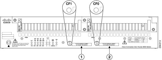
For additional information about the router compact flash memory support, refer to the the router hardware installation guide noted in Supported Hardware.
Configuring the Connected Grid Swap Drive Feature
In this section, the existing router, from which you copy the configuration information we refer to as the source router, and the router to which you transfer the configuration information we refer to as the new router. The new router can be a new router, a replacement router, or a router that has failed.
This section includes the following topics:
•
•
•
•
Enable the Connected Grid Swap Drive Feature
Note
The Connected Grid Swap Drive feature is disabled by default on the router and the ESM.
•
•
To enable the swap drive feature, enter the following global configuration command:
CGR2010(config)# swap-drive
Note
To disable the swap drive feature, enter the following command:
CGR2010(config)# no swap-driveSave Source Running Configuration to the Flash Memory Card
Follow these steps while the source system is operating normally to save the running configuration to the compact flash card.
Router Source Running Configuration
To save the running configuration of the router and boot parameters to the router compact flash card installed in slot CF0, do as follows:
Step 1
CGR2010> write memoryThe write memory command creates two text files on the compact flash card:
•
•
Note
Step 2
CGR2010# dir flash:Directory of flash0:1 -rw- 63822856 Oct 13 2012 21:22:58 cgr2010-universalk9-mz.SPA.152-1.14.T0.22 -rw- 1181 Oct 26 2012 17:26:50 system_swap_drive_config.txt3 -rw- 50865812 Jul 18 2012 18:34:28 cgr2010-universalk9-mz.SPA.151-3.T1.bin4 -rw- 57747592 Aug 24 2012 21:01:32 cgr2010-universalk0-mz.SSA-swapdr5-25 -rw- 87 Oct 26 2012 17:26:50 system_boot_config_txtStep 3
ESM Source Running Configuration
To save the ESM running configuration and boot parameters to the router compact flash card installed in slot CF0, do as follows:

Tip
Cisco Connected Grid Ethernet Switch Module Interface Card Software Configuration Guide.
Step 1
CGR2010# service-module gigabitethernet 0/0/0 session <--Identifies and logs into ESMGRWIC-8PC> write memoryThe write memory command creates two text files on the compact flash card:
•
–
–
•
–
–
Note
Step 2
CGR2010# dir flash:Directory of flash0:1 -rw- 63822856 Oct 13 2012 21:22:58 cgr2010-universalk9-mz.SPA.152-1.14.T0.22 -rw- 1181 Oct 26 2012 17:26:50 sm0_swap_drive_config.txt3 -rw- 50865812 Jul 18 2012 18:34:28 cgr2010-universalk9-mz.SPA.151-3.T1.bin4 -rw- 57747592 Aug 24 2012 21:01:32 cgr2010-universalk0-mz.SSA-swapdr5-25 -rw- 87 Oct 26 2012 17:26:50 sm0_boot_config_txtStep 3
Transfer the Configuration to the New Router
Follow these steps to transfer the saved configuration files to the new router (with or without ESM). This procedure can be performed when the router is off or while the router is operating normally.
Step 1
Step 2
When the router boots up, the ROM monitor software verifies that:
•
•
When the router detects the swap_drive_config.txt file on flash0, the following steps take place:
•
•
Additional Information
•
•
Verify Swap Drive Configuration
 Feedback
Contact Cisco
- Open a Support Case

- (Requires a Cisco Service Contract)
This Document Applies to These Products
- Collaboration Endpoints - Retired Products
- Conferencing - Retired Products
- Contact Center - Retired Products
- Optical Networking - Retired Products
- Routers - Retired Products
- Security - Retired Products
- Servers - Unified Computing (UCS) Retired Products
- Storage Networking Retired Products
- Switches - Retired Products
- Video - Retired Products
- Wireless - Retired Products