Device Settings

After you add a device, you can edit device-related settings on the Device page.

  1. Choose Devices > Device Management.

  2. Next to the device you want to modify, click Edit (edit icon).

  3. Click Device.

Edit general settings

Edit general device settings to customize the device name, packet transfer options, and force deployment settings for managed devices.

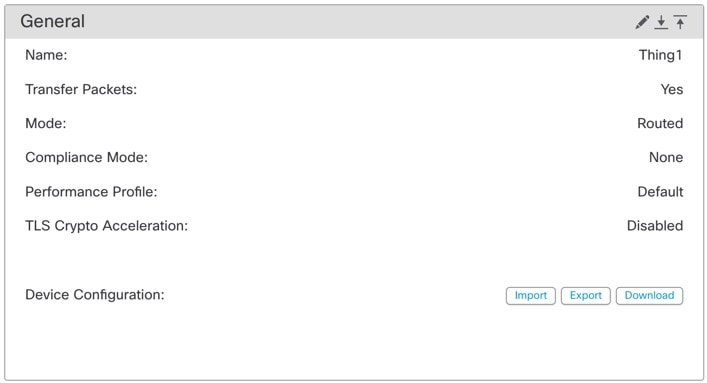
The General section of the Device page displays the settings described in this table.
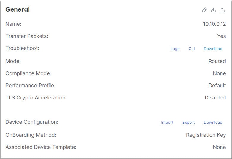
Figure 1. General
General
Table 1. General section table fields

Field

Description

Name

The display name of the device on the Cloud-Delivered Firewall Management Center.

Transfer Packets

This displays whether or not the managed device sends packet data with the events to the Cloud-Delivered Firewall Management Center.

Mode

The displays the mode of the management interface for the device: routed or transparent.

Compliance Mode

This displays the security certifications compliance for a device. Valid values are CC, UCAPL and None.

Performance Profile

This displays the core allocation performance profile for the device, as configured in the platform settings policy.

TLS Crypto Acceleration:

Shows whether TLS crypto acceleration is enabled or disabled.

Device Configuration

Lets you copy, export, or import a configuration. See Copy a configuration to another device and Export and import the device configuration.

OnBoarding Method

Shows whether the device was registered using a registration key or using the serial number (zero-touch provisioning).

You can edit some of these settings from this section.

Procedure


Step 1

Choose Devices > Device Management.

Step 2

Next to the device you want to modify, click Edit (edit icon).

Step 3

Click Device.

Step 4

In the General section, click Edit (edit icon).

  1. Enter a Name for the managed device.

  2. Check Transfer Packets to allow packet data to be stored with events on the Cloud-Delivered Firewall Management Center.

  3. Click Force Deploy to force deployment of current policies and device configuration to the device.

    Note


    Force-deploy consumes more time than the regular deployment since it involves the complete generation of the policy rules to be deployed on the Firewall Threat Defense.

Step 5

For Device Configuration actions, see Copy a configuration to another device and Export and import the device configuration.

Step 6

Click Deploy.


What to do next

  • Deploy configuration changes.

Copy a configuration to another device

Copy configurations and policies from a pre-configured device to a new device, instead of manually reconfiguring the new device.

When a new device is deployed in the network, you can copy configurations and policies from a pre-configured device, instead of manually reconfiguring the new device.

Before you begin

Confirm that:

  • The source and destination devices are the same model and are running the same version of the software.

  • The source is either a standalone device or a high availability pair.

  • The destination device is a standalone device.

  • The source and destination devices have the same number of physical interfaces.

  • The source and destination devices are in the same firewall mode: routed or transparent.

  • The source and destination devices are in the same security-certifications-compliance mode.

  • The source and destination devices are in the same domain.

  • No configuration deployment is in progress on the source or the destination devices.

Follow these steps to copy a configuration to another device:

Procedure


Step 1

Choose Devices > Device Management.

Step 2

Next to the device you want to modify, click Edit (edit icon).

Step 3

Click Device.

Step 4

In the General section, do one of the following:

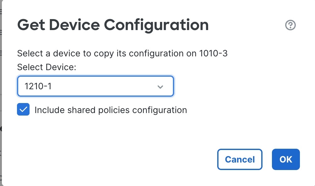
  • Click Get Device Configuration (get device configuration icon) to copy device configuration from another device to the new device. On the Get Device Configuration page, select the source device in the Select Device drop-down list.

  • Click Push Device Configuration (push device configuration icon) to copy device configuration from the current device to the new device. On the Push Device Configuration page, select the destination to which configuration is to be copied in the Target Device drop-down list.

Step 5

(Optional) Check Include shared policies configuration check box to copy policies.

Shared policies such as AC policy, NAT, Platform Settings and FlexConfig policies can be shared across multiple devices.

Step 6

Click OK.

You can monitor the status of the copy device configuration task on Tasks in the Message Center.


When the copy device configuration task is initiated, it erases the configuration on the target device and copies the configuration of the source device to the destination device.


Warning


When you have completed the copy device configuration task, you cannot revert the target device to its original configuration.

Export and import the device configuration

Export device-specific configuration to create a backup that can be imported for the same device in various scenarios including moving the device to a different Cloud-Delivered Firewall Management Center, restoring old configurations, or reregistering a device.

You can export all device-specific configurations available on the Device pages, including:

  • Interfaces

  • Inline Sets

  • Routing

  • DHCP

  • VTEP

  • Associated objects

You can then import the saved configuration for the same device in these use cases:

  • Moving the device to a different Cloud-Delivered Firewall Management Center—First unregister the device from the original Cloud-Delivered Firewall Management Center, then add the device to the new Cloud-Delivered Firewall Management Center. Then you can import the saved configuration.

  • Restore an old configuration—If you deployed changes that negatively impacted the operation of the device, you can import a backup copy of a known working configuration to restore a previous operational state.

  • Reregistering a device—If you unregister a device from the Cloud-Delivered Firewall Management Center, but then want to add it back, you can import the saved configuration.

Before you begin

Review these guidelines:

  • You can only import the configuration to the same device (the UUID must match). You cannot import a configuration to a different device, even if it is the same model.

  • Do not change the version running on the device between exporting and importing; the version must match.

  • If you make inventory changes after your export (such as adding or deleting network modules or configuring or joining breakout ports), the device inventory will not match the Cloud-Delivered Firewall Management Center. In this case, the device inventory will be maintained, and you will be prompted to sync the interfaces (see Sync Interface Changes with the Cloud-Delivered Firewall Management Center) and discard incompatible configuration in the Cloud-Delivered Firewall Management Center when you try to deploy. You will have to repeat the inventory changes and related configuration in the Cloud-Delivered Firewall Management Center.

  • If you export a standalone configuration, you cannot import it to a high availability pair or vice versa.

  • If an object doesn't exist, it will be created. If an object exists, but the value is different, refer to this table:

    Table 2. Object import action

    Scenario

    Import Action

    Object exists with the same name and value.

    Reuse existing objects.

    Object exists with the same name but different value.

    Network and Port objects: Create object overrides for this device. See Object overrides.

    Interface objects: Create new objects. For example, if both the type (security zone or interface group) and the interface type (routed or switched, for example) do not match, then a new object is created.

    All other objects: Reuse existing objects even though the values are different.

    Object doesn't exist.

    Create new objects.

Follow these steps to export and import the device configuration:

Procedure


Step 1

Choose Devices > Device Management.

Step 2

Next to the device you want to edit, click Edit (edit icon).

Step 3

Click Device.

Step 4

Export the configuration.

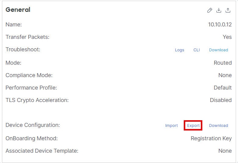
  1. In the General area, click Export.

    Figure 2. Export device configuration
    Export Device Configuration

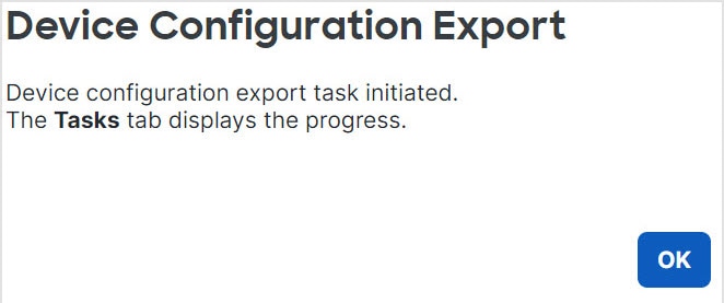
    You are prompted to acknowledge the export; click OK.

    Figure 3. Acknowledge export
    Acknowldge Export

    You can view the export progress in the Tasks page.

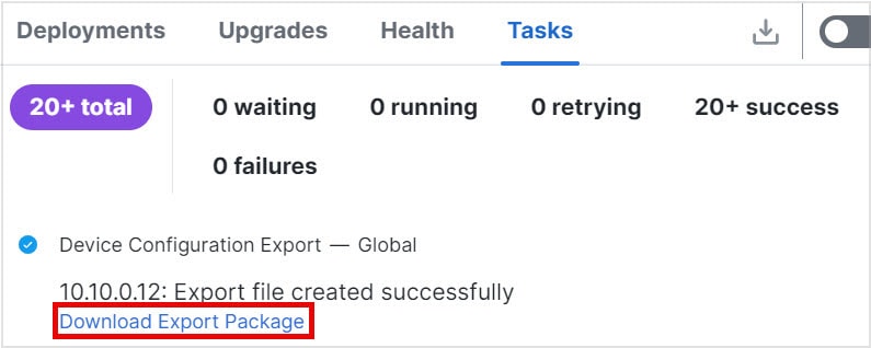
  2. Click Notifications, and then click the Tasks tab. Verify if the export has completed, and then click Download Export Package. Alternatively, you can click the Download button in the General area.

    Figure 4. Export task
    Export Task

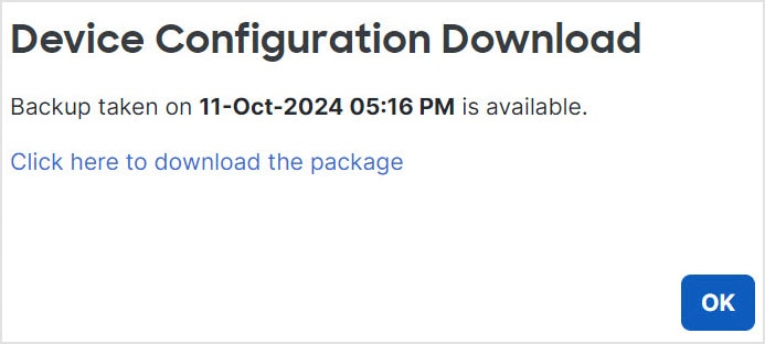
    You are prompted to download the package; click Click here to download the package to save the file locally, and then click OK to exit the dialog box.

    Figure 5. Download package
    Download Package

Step 5

Import the configuration.

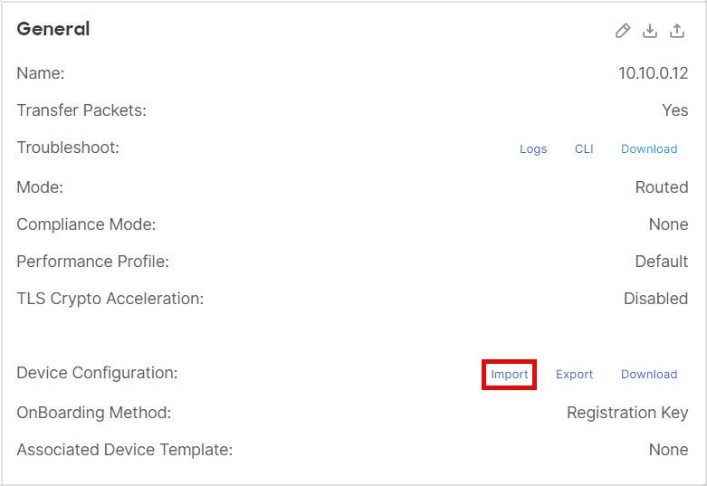
  1. In the General area, click Import.

    Figure 6. Import device configuration
    Import Device Configuration

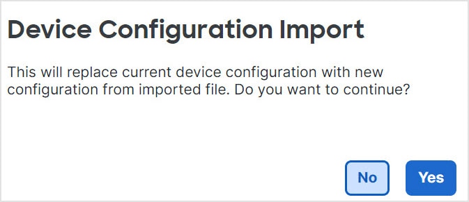
    You are prompted to acknowledge that the current configuration will be replaced. Click Yes and then navigate to the configuration package (with the suffix .sfo; note that this file is different from the Backup/Restore files).

    Figure 7. Import package
    Import Package
    Figure 8. Navigate to package
    Navigate to Package

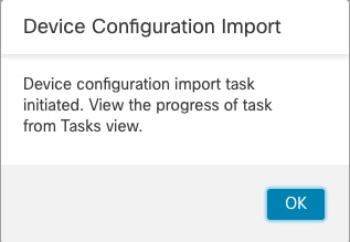
    You are prompted to acknowledge the import; click OK.

    Figure 9. Acknowledge import
    Acknowledge Import

    You can view the import progress in the Tasks page.

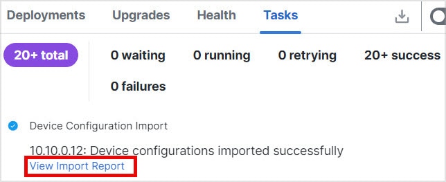
  2. To view the import reports, click Notifications, and then click the Tasks tab. Click View Import Report.

    Figure 10. View import report
    View Import Report

    The Device Configuration Import Reports page provides links to available reports.

    The Device Configuration Import Reports page displays available reports for device configuration imports, indicating successful export and import processes for backup or migration.
  3. Deploy configuration changes.


Edit license settings

Enable or disable specific licenses on your managed device to control which features are available for use.

The License section of the Device page displays the licenses enabled for the device.

You can enable licenses on your device if you have available licenses on your Cloud-Delivered Firewall Management Center.

Procedure


Step 1

Choose Devices > Device Management.

Step 2

Next to the device where you want to enable or disable licenses, click Edit (edit icon).

Step 3

Click Device.

Step 4

In the License section, click Edit (edit icon).

Step 5

Check or clear the check box next to the license you want to enable or disable for the managed device.

Step 6

Click Save.


What to do next

  • Deploy configuration changes.

View system information

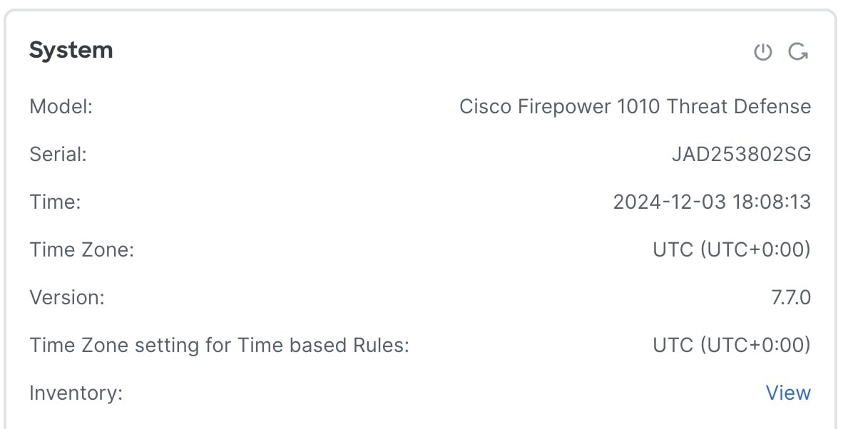
The System section of the Device page displays a read-only table containing system information. You can also shut down or restart the device from this pane, using the icons at the top-right corner.

Figure 11. System
System
Table 3. System section table fields

Field

Description

Shut Down Device (shut down device icon)

Shuts down the device. See Shut down or restart the device.

Restart Device (restart device icon)

Restarts the device. See Shut down or restart the device.

Model

Model name and number.

Serial

PCB (circuit board) serial number. The firewall includes two serial numbers: the chassis serial number and the PCB serial number. The chassis serial number is shown in the Inventory section.

Time

Current system time of the device.

Time Zone

Time zone.

Version

Version of the software currently installed on the managed device.

Time Zone setting for Time based rules

Current system time of the device in the time zone specified in device platform settings.

Inventory

Inventory details. See View Device Inventory.

View device inventory

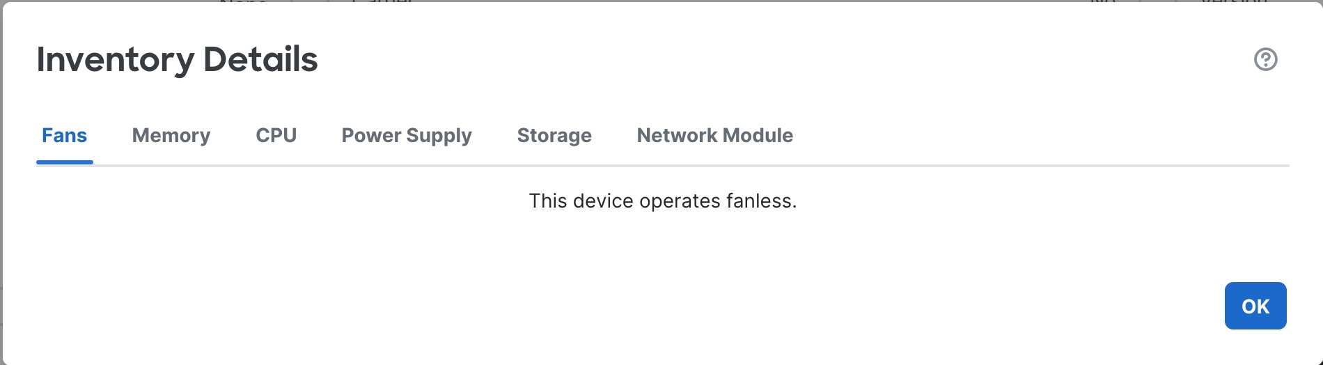
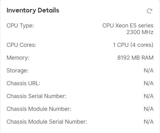
Click View next to Inventory in the System section to view a table of device inventory information including Fans, Memory, CPU, Power Supply, Storage, and Network Modules.

The Inventory Details table displays information about all the Cisco products installed in the Firewall Threat Defense devices assigned with a product identifier (PID). The PID is the product name using which the product can be ordered.

Figure 12. Inventory details
Inventory Details

View the inspection engine

The Inspection Engine section of the Device page shows whether your device uses Snort 2 or Snort 3. To switch the inspection engine, see Enable Snort 3 on an Individual Device in the Custom Snort 3 Intrusion Policies for Access Control .


Note


Snort3 is default for Secure Firewall 1200. It does not support Snort2.


Edit health settings

The Health section of the Device page displays the information described in this table.

Figure 13. Health
Health
Table 4. Health section table fields

Field

Description

Status

An icon that represents the current health status of the device. Clicking the icon displays the Health Monitor for the appliance.

Policy

A link to a read-only version of the health policy currently deployed at the device.

Excluded

A link to the Health Exclude page, where you can enable and disable health exclusion modules.

Out of Band Status

A link to the Out-of-Band configuration details dialog box where you can view out-of-band configuration changes made at the device CLI. You must acknowledge the configuration differences and manually match any changes you want to keep in the Cloud-Delivered Firewall Management Center before the next deployment. See Out-of-band configuration detection.

Out-of-band configuration detection

Out-of-band configuration detection

  • enables select configuration changes directly at the device CLI when you lose the management connection to your device

  • allows restoration of the management connection if you are using a data interface for manager access

  • detects configuration changes on the device after the management connection is restored, requiring manual acknowledgment and synchronization with the Cloud-Delivered Firewall Management Center.

Configuration change purposes

If you lose the management connection to your device, you can make select configuration changes directly at the device CLI to:

  • Restore the management connection if you are using a data interface for manager access

  • Make select configuration changes that can't wait until the connection is restored


Caution


You are expected to know the commands that are required for recovery or emergency use. Do not use this feature to experiment with configuration changes. If you do not know which commands are required or are unsure about the effect of a command, we recommend that you contact Cisco TAC for guidance.


After the management connection is restored, the Cloud-Delivered Firewall Management Center will detect the configuration changes on the device. It does not automatically update the device configuration in the Cloud-Delivered Firewall Management Center.You must view the configuration differences, acknowledge that the device configuration differs, and manually apply the same changes in the Cloud-Delivered Firewall Management Center before deploying.


Caution


When you deploy after acknowledgment, any configurations not present in the Cloud-Delivered Firewall Management Center configuration will be overwritten on the device.


Guidelines for out-of-band configuration

Supported feature areas in recovery-config mode

You can configure the following feature areas at the diagnostic CLI in recovery-config mode:

  • Interfaces

  • Static Routes

  • Dynamic Routing: BGP and OSPF

  • Prefilters

  • Site-to-site VPN

Like other diagnostic CLI commands, refer to the ASA command reference for more information about each command.

Unsupported features

Be aware of these feature limitations in recovery-config mode:

  • Not supported in multi-instance mode.

  • You cannot add or delete EtherChannels.

  • Some platform-dependent interface commands such as speed, duplex, and fec are not supported.

High availability and clustering restrictions

Consider these restrictions when using recovery-config mode in high availability or clustering environments:

  • Recovery-config mode is only available on the active/control node.

  • If a failover or cluster switchover occurs before you exit the recovery-config-mode session, the Cloud-Delivered Firewall Management Center will not detect the change on the new active/control node. We recommend re-entering recovery-config mode on the new active/control node and making a small change to trigger discovery of all of your previous changes. Otherwise, if you do not manually match the changes in the Cloud-Delivered Firewall Management Center, they will be overwritten at deployment without any notification.

  • If you make out-of-band configuration changes on the active/control node and the high availability or cluster enters 'split brain' mode before a configuration sync (for example, due to a failover or cluster-control-link failure), the changes will be lost if a different node becomes active/control after the cluster returns to a healthy state.

  • If you have an active recovery-config-mode session, then new nodes cannot join or rejoin the high availability/cluster until you exit the session.

Additional configuration guidelines

Follow these guidelines when making configuration changes in recovery-config mode:

  • To modify an existing rule or route, delete the existing command using the no form of the command and then re-add the modified rule. This method avoids conflicts and errors. For example:

    Incorrect:

    
    firepower# show running-config route
    route outside 10.0.0.0 255.0.0.0 20.1.1.1 1
    firepower# configure recovery-config
    
     CAUTION: The config CLI is for emergency use only. Use the config CLI if the management center is
    unreachable, and use it only under exceptional circumstances, such as loss of connectivity or
    to restore manager access. Do not change management center's auto-generated configurations.
    
     After your management center is reachable, manually make the same configuration changes in the
    management center. The management center cannot implement them automatically. When you deploy
    from the management center, out-of-band configuration changes will be overwritten. Also, node join
    will be blocked till config CLI session is active, so make sure to exit from the config CLI after
    changes are made.
    
    Would you like to proceed ? [Y]es/[N]o: y
    firepower(recovery-config)# route outside 10.0.0.0 255.0.0.0 30.1.1.1
    firepower(recovery-config)# exit
    Unsaved changes are not kept if you reboot.Save changes to memory ? [Y]es/[N]o: y
    Cryptochecksum: ccfc11a8 4e46d55e 0c99b5ae 3b18a8f1 
    
    3939 bytes copied in 0.70 secs
    firepower# show running-config route                  
    route outside 10.0.0.0 255.0.0.0 20.1.1.1 1
    route outside 10.0.0.0 255.0.0.0 30.1.1.1 1
    firepower#  
     

    In this case, a second route is added instead of replacing the first route.

    Correct:

    
    firepower# show running-config route
    route outside 10.0.0.0 255.0.0.0 20.1.1.1 1
    firepower# configure recovery-config
    
     CAUTION: The config CLI is for emergency use only. Use the config CLI if the management center is
    unreachable, and use it only under exceptional circumstances, such as loss of connectivity or
    to restore manager access. Do not change management center's auto-generated configurations.
    
     After your management center is reachable, manually make the same configuration changes in the
    management center. The management center cannot implement them automatically. When you deploy
    from the management center, out-of-band configuration changes will be overwritten. Also, node join
    will be blocked till config CLI session is active, so make sure to exit from the config CLI after
    changes are made.
    
    Would you like to proceed ? [Y]es/[N]o: y
    firepower(recovery-config)# no route outside 10.0.0.0 255.0.0.0 20.1.1.1
    firepower(recovery-config)# route outside 10.0.0.0 255.0.0.0 30.1.1.1
    firepower(recovery-config)# exit
    Unsaved changes are not kept if you reboot.Save changes to memory ? [Y]es/[N]o: y
    Cryptochecksum: 81bcc51d 43771bbd 15b6dde6 afeb3442 
    
    3945 bytes copied in 0.70 secs
    firepower# show running-config route                  
    route outside 10.0.0.0 255.0.0.0 30.1.1.1 1
    firepower#
    
    
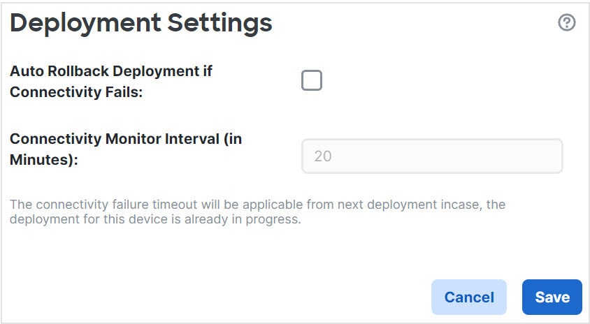
  • If you have auto rollback enabled (refer to Edit deployment settings), and you lose management connectivity because of a deployment, you should not start an out-of-band configuration. Instead, either wait 20 minutes for auto rollback to the previous deployment to occur or manually roll back at the CLI using the configure policy rollback command (refer to Manually Roll Back the configuration if the Cloud-Delivered Firewall Management Center loses Connectivity). Auto rollback will overwrite out-of-band configuration changes if the management connection is still down.

  • For prefilter rules, we don't recommend adding completely new rules (the access-control advanced command). Integration of prefilter rules with the intrusion policy and logging requires the Cloud-Delivered Firewall Management Center, which generates the rule ID and integrates it with other policies.

  • All recovery-config-mode sessions will be logged in syslog with the username "enable_15".

Access recovery-config mode in the diagnostic CLI

This task allows you to make out-of-band configuration changes when the management connection is down using the diagnostic CLI recovery-config mode.

You can use the diagnostic CLI recovery-config mode to make out-of-band configuration changes when the management connection is down. Be sure to make the same changes in the Cloud-Delivered Firewall Management Center. Local changes will always be overwritten by the Cloud-Delivered Firewall Management Center deployment.

For high availability and clustering, make your changes on the active/control node. This mode is not supported in multi-instance mode.

Procedure

Step 1

Connect to the device CLI using either the console port or SSH.

See Log into the Command-Line Interface on the device.

Step 2

Access the diagnostic CLI.

system support diagnostic-CLI

enable (Press enter without entering a password when prompted.)

Example:

> system support diagnostic-cli
firepower> enable
Password:  

Step 3

Show the current running configuration for reference.

show running-config

Note


You cannot enter show commands in recovery-config mode.

Step 4

Enter recovery-config mode.

configure recovery-config

Example:
firepower# configure recovery-config

 CAUTION: The config CLI is for emergency use only. Use the config CLI if the management center is
unreachable, and use it only under exceptional circumstances, such as loss of connectivity or
to restore manager access. Do not change management center's auto-generated configurations.

 After your management center is reachable, manually make the same configuration changes in the
management center. The management center cannot implement them automatically. When you deploy
from the management center, out-of-band configuration changes will be overwritten. Also, node join
will be blocked till config CLI session is active, so make sure to exit from the config CLI after
changes are made.

Would you like to proceed ? [Y]es/[N]o: y
firepower(recovery-config)#           

Step 5

You can now enter select configuration commands.

Enter ? to view available commands.

See Guidelines for out-of-band configuration for supported feature areas.

See the ASA configuration guides or command reference for details about the commands.

Tip


Keep track of all of the commands you changed. Although the Cloud-Delivered Firewall Management Center shows you the differential later, it's good practice to keep a record of your command changes in case you need to make iterative changes for restoring the management connection.

Example:

firepower(recovery-config)# ?

  access-list           Configure an access control element
  as-path               BGP autonomous system path filter
  bfd                   BFD configuration commands
  bfd-template          BFD template configuration
  cluster               Cluster configuration
  community-list        Add a community list entry
  crypto                Configure IPSec, ISAKMP, Certification authority, key
  end                   Exit from configure mode
  exit                  Exit from config mode
  extcommunity-list     Add a extended community list entry
  group-policy          Configure or remove a group policy
  interface             Select an interface to configure
  ip                    Configure IP address pools
  ipsec                 Configure transform-set, IPSec SA lifetime and PMTU
                        Aging reset timer
  ipv6                  Configure IPv6 address pools
  ipv6                  Global IPv6 configuration commands
  isakmp                Configure ISAKMP options
  jumbo-frame           Configure jumbo-frame support
  mac-address           MAC address options
  management-interface  Management interface
  mtu                   Specify MTU(Maximum Transmission Unit) for an interface
  
  no                    Negate a command or set its defaults
  
  policy-list           Define IP Policy list
  prefix-list           Build a prefix list
  route                 Configure a static route for an interface
  route-map             Create route-map or enter route-map configuration mode
  router                Enable a routing process
  sla                   IP Service Level Agreement
  sysopt                Set system functional options
  time-range            Define time range entries
  tunnel-group          Create and manage the database of connection specific
                        records for IPSec connections
  vpdn                  Configure VPDN feature
  vrf                   Configure a VRF
  zone                  Create or show a Zone
firepower(recovery-config)#

Step 6

Exit recovery-config mode to be prompted to save your changes. Enter exit to exit each submode until you return to enable mode.

You can choose to save your changes to the startup configuration or keep changes only in the running configuration by not saving. Running configuration changes won't be retained after a reboot. If you make additional changes later and decide to save the configuration, all of your previous changes are also saved, since the entire running configuration is saved.

Deployment is be blocked when the recovery-config-mode session is open.

Example:

firepower(recovery-config)# interface Ethernet0/1
firepower(config-if)# ip address 10.0.0.2 255.0.0.0
firepower(config-if)# exit
firepower(recovery-config)# exit
Unsaved changes are not kept if you reboot. Save changes to memory ? [Y]es/[N]o: y

Cryptochecksum: 81a9073e f9535916 9c333d7e 9a3e5e76 

3756 bytes copied in 0.70 secs
firepower#  

Unsaved changes are not kept if you reboot. Save changes to memory ? [Y]es/[N]o: 

Cryptochecksum: 81a9073e f9535916 9c333d7e 9a3e5e76 

3756 bytes copied in 0.70 secs
firepower#

Step 7

Return to the Firewall Threat Defense CLI by typing Ctrl+a, then d, or you can enter exit to exit each mode.

Note


If you type Ctrl+a, then d to return to the Firewall Threat Defense CLI without first exiting recovery-config mode, the recovery-config-mode session will remain open, and deployment will be blocked.

Example:

firepower# exit

Logoff

User enable_1 logged in to firepower
Logins over the last 1 days: 4.  Last login: 20:42:51 UTC Dec 4 2024 from console
Failed logins since the last login: 0.
Type help or '?' for a list of available commands.
firepower> exit
Console connection detached.
>                                            
                                                       

Acknowledge the out-of-band configuration

This task acknowledges out-of-band configuration changes detected by the Cloud-Delivered Firewall Management Center and enables deployment by matching configurations within the system.

When the Cloud-Delivered Firewall Management Center detects an out-of-band configuration change on a device, you must acknowledge the changes and match the configuration within the Cloud-Delivered Firewall Management Center that you want to keep. Until you acknowledge the changes, deployment will be blocked.

Procedure

Step 1

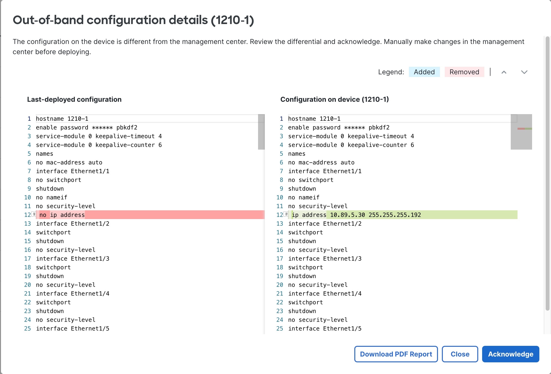
Open the Out-of-Band configuration details dialog box.

Figure 14. Out-of-Band configuration details
Out-of-Band Configuration Details

Note


Some commands, when set to a default setting, don't appear in the command output. However, the non-default command will show on either side as green (added) or red (removed). For example, if you add no shutdown to an interface in recovery-config mode, the shutdown command will show in red on the left Last-deployed configuration pane while no shutdown will not appear in the right Configuration on device pane. In this case, although the default setting for an interface is shutdown , the parser considers no shutdown to be the default and doesn't show it.

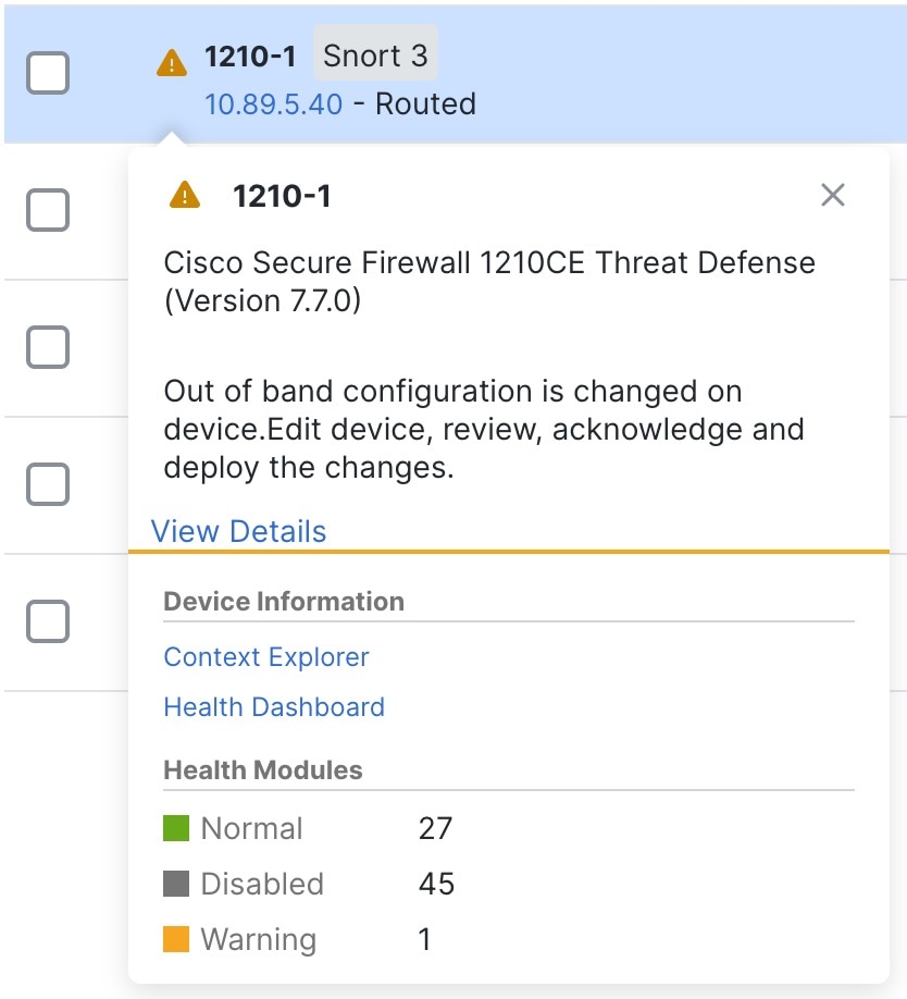
You can open the dialog box from multiple locations. For example, on the Devices > Device Management page, your device will have a warning. Click View Details.

Figure 15. Device management warning
Device Management Warning

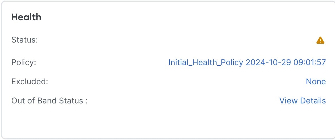
Or, from the Devices > Device Management, and then navigate to Health tile under Device tab, you can click View Details.

Figure 16. Health Out-of-Band status
Health Out-of-Band Status

Note


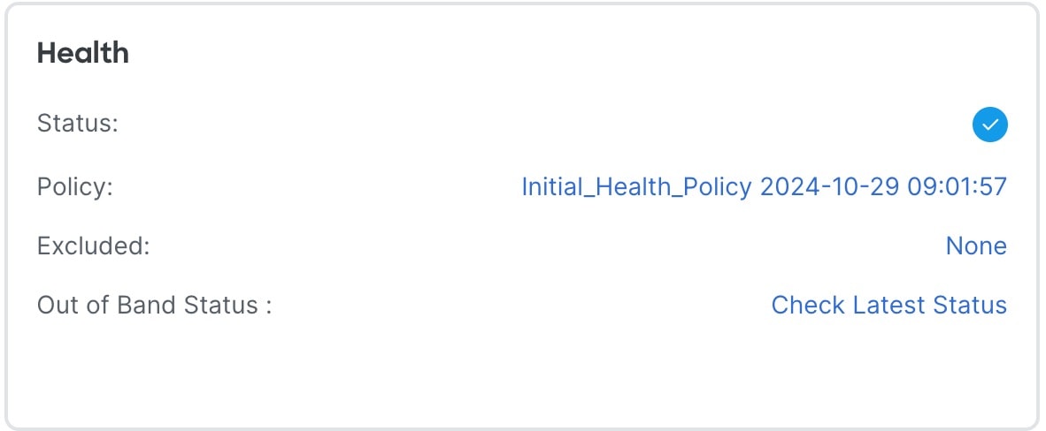
If the out-of-band notification hasn't yet reached the Cloud-Delivered Firewall Management Center, you can check for changes using the Check Latest Status link in the Health tile.

Step 2

Click Download PDF Report so you can refer to the configuration changes you need to make after you close the dialog box.

Or you can bring up the dialog box at any time to review the changes.

Step 3

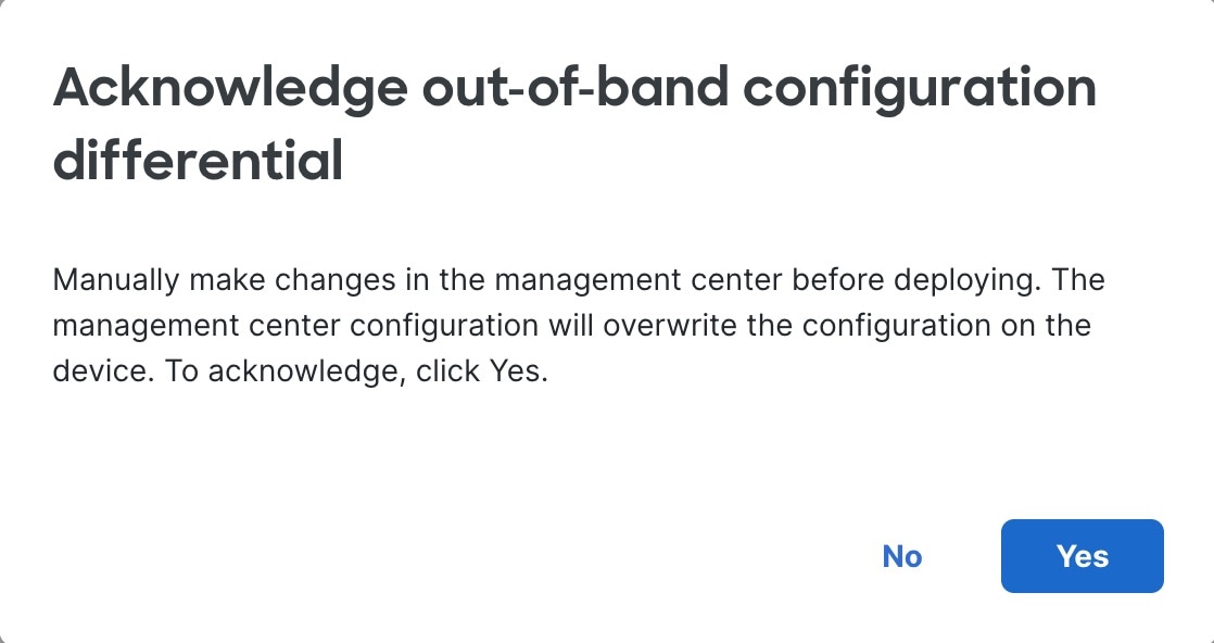
Click Acknowledge, and then Yes.

Figure 17. Acknowledge
Acknowledge

If you want to prevent an accidental deployment until after you've made your configuration changes, you can instead make the changes and then come back and click Acknowledge.

Step 4

Click Close on the Out-of-Band configuration details dialog box.

You can still revisit the dialog box to review the changes you need to make until you deploy. The status on the Device page changes to show you have acknowledged the out-of-band configuration:

Figure 18. Acknowledgement status
Acknowledged Status

Step 5

Make the configuration changes that you made at the CLI.

You'll need to match the configuration CLI to Cloud-Delivered Firewall Management Center screens; there aren't links from the CLI changes directly to screens.

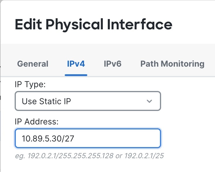
If you don't want to keep your changes, you can simply deploy and overwrite the device configuration. You should make all necessary changes to maintain the management connection as well as any other changes you want to keep. For example, if you changed the IP address at the CLI, you need to go to the Interfaces page, edit the interface, and set that IP address to match:

Figure 19. Match the IP address change
Match the IP Address Change

There is no checking mechanism that you made the same change; you could set the IP address differently if you want.

Step 6

Deploy configuration changes.

After you deploy, you can view the configuration differential—whether you made the changes or not—on the System (system gear icon) > Monitoring > Audit page. Check for the subsystem called Device > Device Management > Out of band changes.


Edit management settings

These settings control how the Cloud-Delivered Firewall Management Center establishes the management connection with the device.

Configure a redundant manager access data interface

This task configures a redundant manager access data interface to ensure continuous management connectivity. The secondary interface provides automatic failover capabilities when the primary management interface becomes unavailable, maintaining device management functionality.

When you use a data interface for manager access, you can configure a secondary data interface to take over management functions if the primary interface goes down. You can configure only one secondary interface. The device uses SLA monitoring to track the viability of the static routes and an ECMP zone that contains both interfaces so management traffic can use both interfaces.

Before you begin

  • The secondary interface needs to be in a separate security zone from the primary interface.

  • All of requirements apply to the primary interface also apply to the secondary interface.

Follow these steps to configure a redundant manager access data interface:

Procedure


Step 1

On the Devices > Device Management page, click Edit (edit icon) for the device.

Step 2

Enable manager access for the secondary interface.

This setting is in addition to standard interface settings such as enabling the interface, setting the name, setting the security zone, and setting a static IPv4 address.

  1. Choose Interfaces > Edit Physical Interface > Manager Access.

  2. Check Enable management on this interface for the Manager.

  3. Click OK.

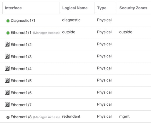
Both interfaces show (Manager Access) in the interface listing.

Figure 20. Interface listing
Interface Listing

Step 3

Add the secondary address to the Management settings.

  1. Click Device, and view the Management area.

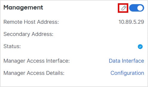
  2. Click Edit (edit icon).

    Figure 21. Edit management address
    Edit Management Address
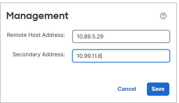
  3. In the Management dialog box, modify the name or IP address in the Secondary Address field

    Figure 22. Management IP address
    Management IP Address
  4. Click Save.

Step 4

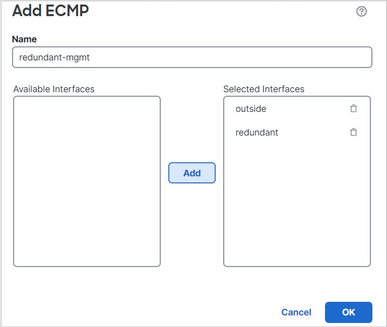
Create an ECMP zone with both interfaces.

  1. Click Routing.

  2. From the virtual router drop-down, choose the virtual router in which the primary and secondary interfaces reside.

  3. Click ECMP, and then click Add.

  4. Enter a Name for the ECMP zone.

  5. Select the primary and secondary interfaces under the Available Interfaces box, and then click Add.

    Figure 23. Add an ECMP zone
    Add an ECMP Zone
  6. Click OK, and then Save.

Step 5

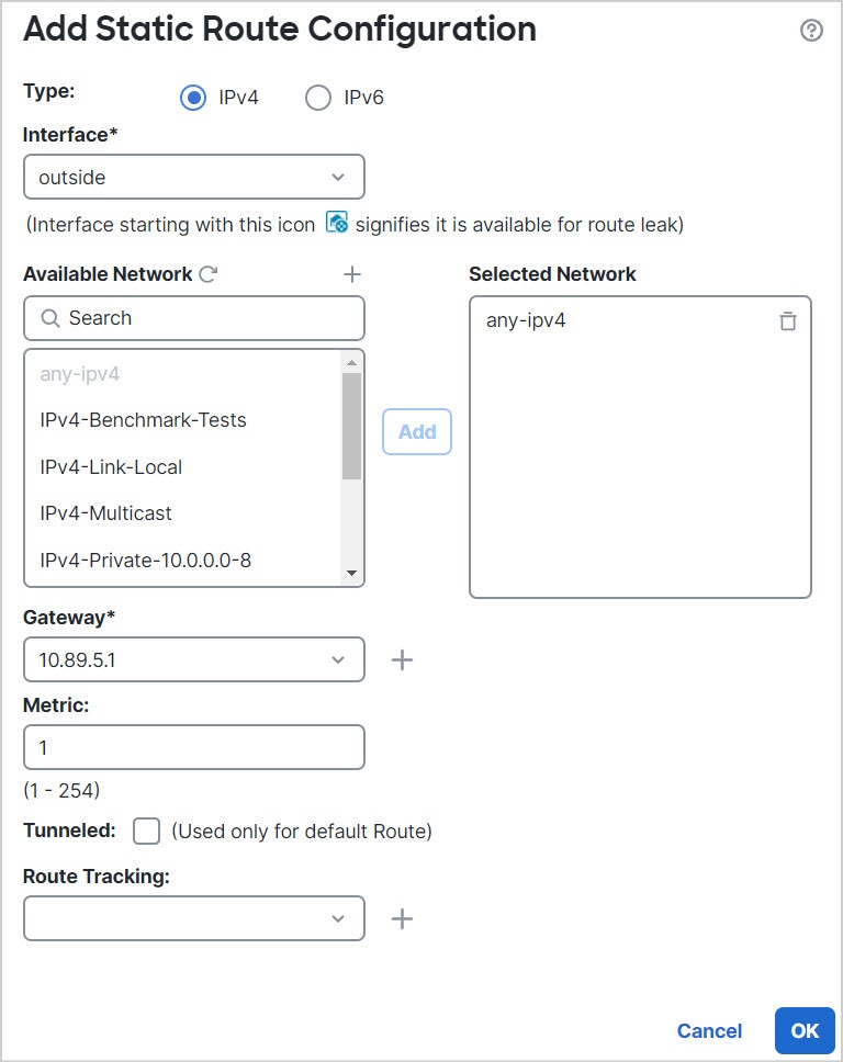
Add equal-cost default static routes for both interfaces and enable SLA tracking on both.

The routes should be identical except for the gateway and should both have metric 1. The primary interface should already have a default route that you can edit.

Figure 24. Add/Edit static route
Add/Edit Static Route
  1. Click Static Route.

  2. Either click Add Route to add a new route, or click Edit (edit icon) for an existing route.

  3. From the Interface drop-down, choose the interface.

  4. For the destination network, select any-ipv4 from the Available Networks box and click Add.

  5. Enter the default Gateway.

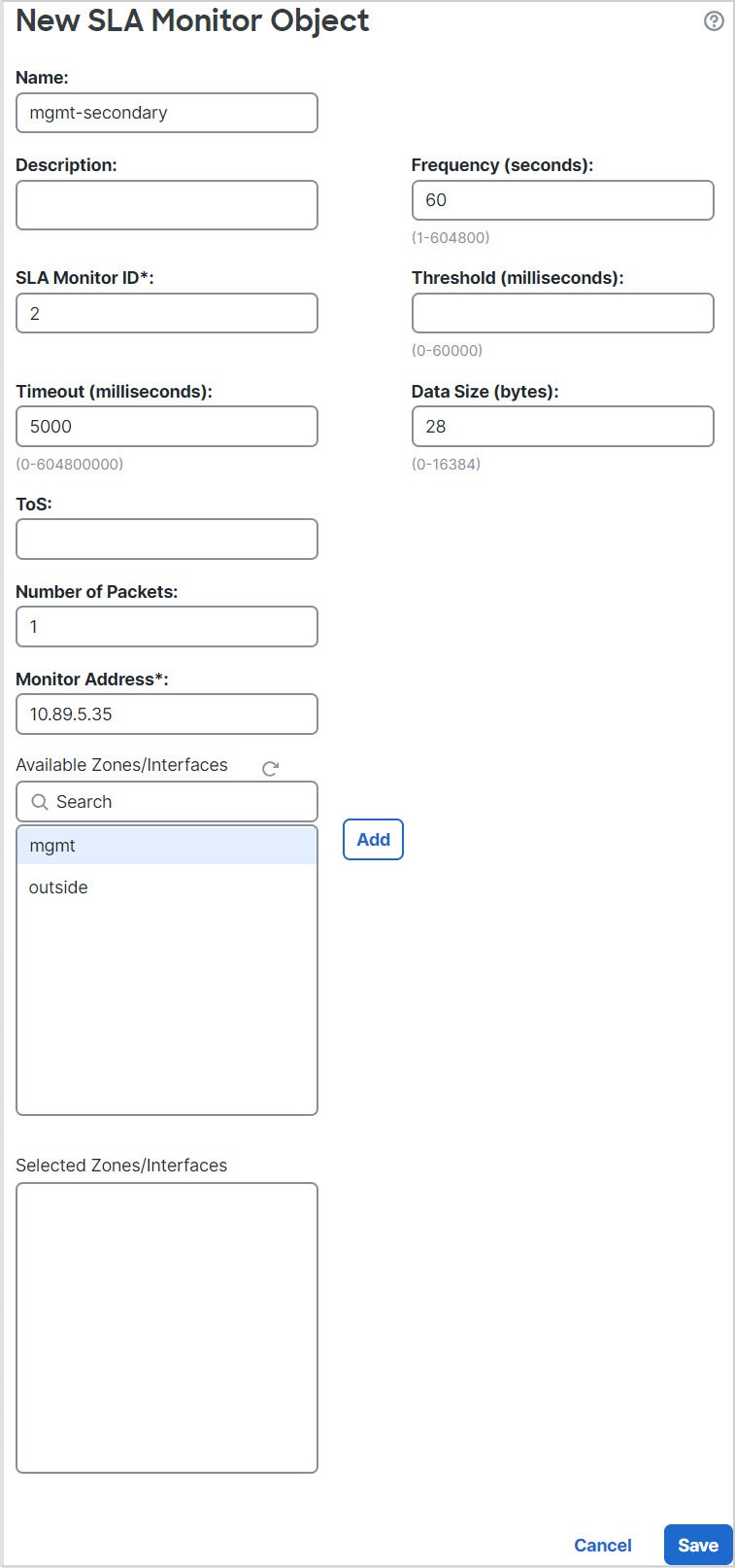
  6. For Route Tracking, click Add (add icon) to add a new SLA monitor object.

  7. Enter the required parameters including the following:

    • The Monitor Address as the Cloud-Delivered Firewall Management Center IP address.

    • The zone for the primary or secondary management interface in Available Zones; for example, choose the outside zone for the primary interface object, and the mgmt zone for the secondary interface object.

    See Configure an SLA monitor for more information.

    Figure 25. Add SLA monitor
    Add SLA Monitor
  8. Click Save, then choose the SLA object you just created in the Route Tracking drop-down list.

  9. Click OK, and then Save.

    Repeat for the default route for the other management interface.

Step 6

Deploy configuration changes.

To deploy this feature, the Cloud-Delivered Firewall Management Center enables the secondary interface for management traffic, including auto-generated policy-based routing configuration for management traffic to get to the right data interface. The Cloud-Delivered Firewall Management Center also deploys a second instance of the configure network management-data-interface command. Note that if you edit the secondary interface at the CLI, you cannot configure the gateway or otherwise alter the default route, because the static route for this interface can only be edited in the Cloud-Delivered Firewall Management Center.


Change manager access interface settings

Changing manager interface settings on the device or on the Cloud-Delivered Firewall Management Center can disrupt the management connection. Review these scenarios that change interface settings and reestablish the management connection.

Change the device IP address

Change the device IP address, and then update the address in the Cloud-Delivered Firewall Management Center.

Set the device IP address

Use one of these methods to set the manager access interface IP address.

Modify Firewall Threat Defense management interface settings at the CLI

Many management interface settings are set during device initial setup; this task allows you to update them, add event-only interfaces (if supported), or configure static routes, DNS domains, and other advanced settings. Use the CLI when you need direct device access or troubleshooting. If you wish to configure network settings for a data interface used for management, use the device management center interface instead.


Note


This topic applies to the dedicated management interface. You can alternatively configure a data interface for management. If you want to change network settings for that interface, you should do so within Cloud-Delivered Firewall Management Center and not at the CLI. If you need to troubleshoot a disrupted management connection, and need to make changes directly on the Firewall Threat Defense , see Modify the Firewall Threat Defense data interface used for management at the CLI .


For information about the Firewall Threat Defense CLI, see the Cisco Secure Firewall Threat Defense Command Reference .

Before you begin

  • You can create user accounts that can log into the CLI using the configure user add command ; see Add an internal user at the CLI . You can also configure AAA users according to Configure external authentication .

  • Be cautious when making changes to the management interface using SSH. If you cannot re-connect because of a configuration error, access the device console port.

  • In high-availability configurations, when you modify the management IP address of a registered device from the device CLI or from the Cloud-Delivered Firewall Management Center , the standby Cloud-Delivered Firewall Management Center does not reflect the changes even after a high-availability synchronization. To ensure that the standby Cloud-Delivered Firewall Management Center is also updated, switch roles between the two Cloud-Delivered Firewall Management Center s, making the secondary Cloud-Delivered Firewall Management Center as the active unit. Modify the management IP address of the registered device on the Device Management page of the standby Cloud-Delivered Firewall Management Center .

Procedure

Step 1

Connect to the device CLI, either from the console port or using SSH.

Step 2

Log in with the Admin username and password.

Step 3

(Firepower 4100/9300 /Secure Firewall 4200 only) Enable the second management interface as an event-only interface.

configure network management-interface enable management1

configure network management-interface disable-management-channel management1

You always need a management interface for management traffic. If your device has a second management interface, you can enable it for event-only traffic.

(Optional) Disable events for the main management interface using the configure network management-interface disable-events-channel command. In either case, the device will try to send events on the event-only interface, and if that interface is down, it will send events on the management interface even if you disable the event channel.

You cannot disable both event and management channels on an interface.

To use a separate event interface, you must enable an event-only interface on the Cloud-Delivered Firewall Management Center that is dedicated exclusively to event traffic. See the Cisco Secure Firewall Management Center Administration Guide .

Example:
> configure network management-interface enable management1
Configuration updated successfully
> configure network management-interface disable-management-channel management1
Configuration updated successfully
>

Step 4

Configure the IP address of the management interface and/or event interface:

If you do not specify the management_interface argument, then you change the network settings for the default management interface. When configuring an event interface, be sure to specify the management_interface argument. The event interface can be on a separate network from the management interface, or on the same network. If you are connected to the interface you are configuring, you will be disconnected. You can re-connect to the new IP address.

  1. Configure the IPv4 address:

    • Manual configuration:

      configure network ipv4 manual ip_address netmask gateway_ip [ management_interface ]

      Note that the gateway_ip in this command is used to create the default route for the device. If you configure an event-only interface, then you must enter the gateway_ip as part of the command; however, this entry just configures the default route to the value you specify and does not create a separate static route for the eventing interface. If you are using an event-only interface on a different network from the management interface, we recommend that you set the gateway_ip for use with the management interface, and then create a static route separately for the event-only interface using the configure network static-routes command.

      Example:

      > configure network ipv4 manual 10.10.10.45 255.255.255.0 10.10.10.1 management1
      Setting IPv4 network configuration.
      Network settings changed.
      >
    • DHCP (supported on the default management interface only):

      configure network ipv4 dhcp

  2. Configure the IPv6 address:

    • Stateless autoconfiguration:

      configure network ipv6 router [ management_interface ]

      Example:

      > configure network ipv6 router management0
      Setting IPv6 network configuration.
      Network settings changed.
      >
    • Manual configuration:

      configure network ipv6 manual ip6_address ip6_prefix_length [ ip6_gateway_ip ] [ management_interface ]

      Note that the ipv6_gateway_ip in this command is used to create the default route for the device. If you configure an event-only interface, then you must enter the ipv6_gateway_ip as part of the command; however, this entry just configures the default route to the value you specify and does not create a separate static route for the eventing interface. If you are using an event-only interface on a different network from the management interface, we recommend that you set the ipv6_gateway_ip for use with the management interface, and then create a static route separately for the event-only interface using the configure network static-routes command.

      Example:

      > configure network ipv6 manual 2001:0DB8:BA98::3210 64 management1
      Setting IPv6 network configuration.
      Network settings changed.
      >
    • DHCPv6 (supported on the default management interface only):

      configure network ipv6 dhcp

  3. For IPv6, enable or disable ICMPv6 Echo Replies and Destination Unreachable messages. These messages are enabled by default.

    configure network ipv6 destination-unreachable { enable | disable }

    configure network ipv6 echo-reply { enable | disable }
    You might want to disable these packets to guard against potential denial of service attacks. Disabling Echo Reply packets means you cannot use IPv6 ping to the device management interfaces for testing purposes.

    Example:
    > configure network ipv6 destination-unreachable disable
    > configure network ipv6 echo-reply disable

Step 5

Enable a DHCP server on the default management interface to provide IP addresses to connected hosts:

configure network ipv4 dhcp-server-enable start_ip_address end_ip_address

Example:
> configure network ipv4 dhcp-server-enable 10.10.10.200 10.10.10.254
DHCP Server Enabled
>

You can only configure a DHCP server when you set the management interface IP address manually. This command is not supported on the Firewall Management Center Virtual . To display the status of the DHCP server, enter show network-dhcp-server :

> show network-dhcp-server
DHCP Server Enabled
10.10.10.200-10.10.10.254

Step 6

Add a static route for the event-only interface if the Cloud-Delivered Firewall Management Center is on a remote network. Otherwise, all traffic will match the default route through the management interface.

configure network static-routes { ipv4 | ipv6 } add management_interface destination_ip netmask_or_prefix gateway_ip

For the default route, do not use this command; you can only change the default route gateway IP address when you use the configure network ipv4 or ipv6 commands (see Step 4 ).

Example:
> configure network static-routes ipv4 add management1 192.168.6.0 255.255.255.0 10.10.10.1
Configuration updated successfully
> configure network static-routes ipv6 add management1 2001:0DB8:AA89::5110 64 2001:0DB8:BA98::3211
Configuration updated successfully
>

To display static routes, enter show network-static-routes (the default route is not shown):

> show network-static-routes
---------------[ IPv4 Static Routes ]---------------
Interface                 : management1
Destination               : 192.168.6.0
Gateway                   : 10.10.10.1
Netmask                   : 255.255.255.0
[…]

Step 7

Do these settings:

  1. Set the hostname:

    configure network hostname name

    Example:
    > configure network hostname farscape1.cisco.com

    Syslog messages do not reflect a new hostname until after a reboot.

  2. Set the search domains:

    configure network dns searchdomains domain_list

    Example:
    > configure network dns searchdomains example.com,cisco.com

    Set the search domain(s) for the device, separated by commas. These domains are added to hostnames when you do not specify a fully-qualified domain name in a command, for example, ping system . The domains are used only on the management interface, or for commands that go through the management interface.

  3. Set up to 3 DNS servers, separated by commas:

    configure network dns servers dns_ip_list

    Example:
    > configure network dns servers 10.10.6.5,10.20.89.2,10.80.54.3
  4. Set the remote management port for communication with the Cloud-Delivered Firewall Management Center :

    configure network management-interface tcpport number

    Example:
    > configure network management-interface tcpport 8555

    The Cloud-Delivered Firewall Management Center and managed devices communicate using a two-way, TLS-1.3-encrypted communication channel, which by default is on port 8305. Do not change the management port when using multi-instance mode; only port 8305 is supported.

    Note


    We recommend that you keep the default settings for the remote management port, but if the management port conflicts with other communications on your network, you can choose a different port. If you change the management port, you must change it for all devices in your deployment that need to communicate with each other.

  5. ( Firewall Threat Defense only) Set the management or eventing interface MTU. The MTU is 1500 bytes by default.

    configure network mtu [ bytes ] [ interface_id ]

    • bytes —Sets the MTU in bytes. For the management interface, the value can be between 64 and 1500 if you enable IPv4, and 1280 to 1500 if you enable IPv6. For the eventing interface, the value can be between 64 and 9000 if you enable IPv4, and 1280 to 9000 if you enable IPv6. If you enable both IPv4 and IPv6, then the minimum is 1280. If you do not enter the bytes , you are prompted for a value.

    • interface_id —Specifies the interface ID on which to set the MTU. Use the show network command to see available interface IDs, for example management0, management1, br1, and eth0, depending on the platform. If you do not specify an interface, then the management interface is used.

    Example:
    > configure network mtu 8192 management1
    MTU set successfully to 1500 from 8192 for management1
    Refreshing Network Config...
    NetworkSettings::refreshNetworkConfig MTU value at start 8192
    Interface management1 speed is set to '10000baseT/Full'
    NetworkSettings::refreshNetworkConfig MTU value at end 8192
    >
  6. Configure an HTTP proxy. The device is configured to directly connect to the internet on ports TCP/443 (HTTPS) and TCP/80 (HTTP). You can use a proxy server, to which you can authenticate via HTTP Digest. After issuing the command, you are prompted for the HTTP proxy address and port, whether proxy authentication is required, and if it is required, the proxy username, proxy password, and confirmation of the proxy password.

    Note

     
    For proxy password on Firewall Threat Defense , you can use A-Z, a-z, and 0-9 characters only.

    configure network http-proxy

    Example:
    > configure network http-proxy
    Manual proxy configuration
    Enter HTTP Proxy address: 10.100.10.10
    Enter HTTP Proxy Port: 80
    Use Proxy Authentication? (y/n) [n]: Y
    Enter Proxy Username: proxyuser
    Enter Proxy Password: proxypassword
    Confirm Proxy Password: proxypassword

Step 8

If you change the device management IP address, then see the following tasks for Cloud-Delivered Firewall Management Center connectivity. Perform these tasks depending on how you identified the Cloud-Delivered Firewall Management Center during initial device setup using the configure manager add command :


Modify the Firewall Threat Defense data interface used for management at the CLI

This task allows you to specify a new data interface to replace the old interface when the management connection has been disrupted and you need to restore connectivity between the Firewall Threat Defense and the Cloud-Delivered Firewall Management Center.

If the management connection is active, make changes to an existing data interface using the Cloud-Delivered Firewall Management Center (see Modify the Firewall Threat Defense data interface used for management in the GUI). For initial setup of the data management interface, see the configure network management-data-interface command.

For high-availability pairs, perform all CLI steps on both units. Within the Cloud-Delivered Firewall Management Center, perform steps only on the active unit. Once the configuration changes are deployed, the standby unit synchronizes configuration and other state information from the active unit.


Note


This topic applies to the data interface that you configured for Management, not the dedicated Management interface. If you want to change network settings for the Management interface, see Modify Firewall Threat Defense management interface settings at the CLI.


For information about the Firewall Threat Defense CLI, see the Cisco Secure Firewall Threat Defense Command Reference.

Before you begin

If you are changing the data management interface to a new interface, move the current interface cable to the new interface.

Procedure

Step 1

Connect to the device CLI.

Use the console port when executing these commands. If you are performing initial setup, then you may be disconnected from the Management interface. If you are editing the configuration due to a disrupted management connection and have SSH access to the dedicated management interface, you can use the SSH connection.

  1. Log in with the admin username and password.

Step 2

Disable the interface so you can reconfigure its settings.

configure network management-data-interface disable

Note


If you only want to set a new IPv4 address on the same interface and not make any other changes, you can skip this step. Other changes require you to disable the interface first.

Example:

> configure network management-data-interface disable

 Configuration updated successfully..!!


Configuration disable was successful, please update the default route to point to a gateway on management interface using the command 'configure network'

Step 3

Configure the new data interface for manager access.

configure network management-data-interface

You are then prompted to configure basic network settings for the data interface.

If you change the data management interface to a new interface on the same network, use the same settings as for the previous interface except the interface ID. In addition, for the Do you wish to clear all the device configuration before applying ? (y/n) [n]: option, choose y. This choice will clear the old data management interface configuration, so that you can successfully reuse the IP address and interface name on the new interface.


> configure network management-data-interface
Data interface to use for management: ethernet1/4
Specify a name for the interface [outside]: internet
IP address (manual / dhcp) [dhcp]: manual
IPv4/IPv6 address: 10.10.6.7
Netmask/IPv6 Prefix: 255.255.255.0
Default Gateway: 10.10.6.1
Comma-separated list of DNS servers [none]: 208.67.222.222,208.67.220.220
DDNS server update URL [none]:
Do you wish to clear all the device configuration before applying ? (y/n) [n]: y

Configuration done with option to allow manager access from any network, if you wish to change the manager access network
use the 'client' option in the command 'configure network management-data-interface'.

Setting IPv4 network configuration.
Network settings changed.

>
  1. Limit data interface access to the Cloud-Delivered Firewall Management Center on a specific network.

    configure network management-data-interface client ip_address netmask

    By default, all networks are allowed.

Step 4

Update the Hostname or IP Address in the Cloud-Delivered Firewall Management Center.

The connection may be reestablished automatically, but disabling and reenabling the connection in the Cloud-Delivered Firewall Management Center will help the connection reestablish faster. Or you may need to update the device IP address in the Cloud-Delivered Firewall Management Center according to the linked procedure.

Step 5

Check that the management connection was reestablished.

sftunnel-status-brief

See the sample output for a connection that is up, with peer channel and heartbeat information:


> sftunnel-status-brief
PEER:10.10.17.202
Peer channel Channel-A is valid type (CONTROL), using 'eth0', connected to '10.10.17.202' via '10.10.17.222'
Peer channel Channel-B is valid type (EVENT), using 'eth0', connected to '10.10.17.202' via '10.10.17.222'
Registration: Completed.
IPv4 Connection to peer '10.10.17.202' Start Time: Wed Jun 10 14:27:12 2020 UTC
Heartbeat Send Time: Mon Jun 15 09:02:08 2020 UTC
Heartbeat Received Time: Mon Jun 15 09:02:16 2020 UTC

Step 6

In the Cloud-Delivered Firewall Management Center, choose Devices > Device Management, and click Edit (edit icon). In the Device area, against the Management field, click Refresh next to Manager Access - Configuration Details.

The Cloud-Delivered Firewall Management Center detects the interface and default route configuration changes and blocks deployment to the device. When you change the data interface settings locally on the device, you must reconcile those changes in the Cloud-Delivered Firewall Management Center manually. You can view the discrepancies between the Cloud-Delivered Firewall Management Center and the device on the Configuration tab.

Step 7

Choose Interfaces, and make the changes.

  1. Remove the IP address and name from the old data management interface and disable manager access for this interface.

  2. Configure the new data management interface with the new settings (the ones you used at the CLI) and enable manager access for it.

Step 8

Under the Routing tab, click Static Route, and change the default route from the old data management interface to the new one.

Step 9

Return to the Manager Access - Configuration Details dialog box, and click Acknowledge to remove the deployment block.

The next time you deploy, the Cloud-Delivered Firewall Management Center configuration will overwrite any remaining conflicting settings on the Firewall Threat Defense. It is your responsibility to manually fix the configuration in the Cloud-Delivered Firewall Management Center before you re-deploy.

You will see expected messages of "Config was cleared" and "Manager access changed and acknowledged."


Modify the Firewall Threat Defense data interface used for management in the GUI

Configure the data interface IP address settings to change the management connection or update the interface used for manager access.

If the management connection is up but you want to change the IP address of the data interface used for manager access, follow these steps. For example, if you register a device using zero-touch provisioning, then you need to change the IP address to a static address before you can enable high availability.

You can alternatively change interface settings at the CLI, but we recommend using that method only if the management connection is down. Any changes you make at the CLI should be replicated in the GUI.

Procedure

Step 1

Choose Devices > Device Management, and click Edit (edit icon) next to the device.

Step 2

Choose Interfaces.

Step 3

If you want to change the interface used for manager access:

  1. Remove the IP address and name from the old data management interface and disable manager access for this interface.

  2. Configure the new data management interface with the new settings and enable manager access for it.

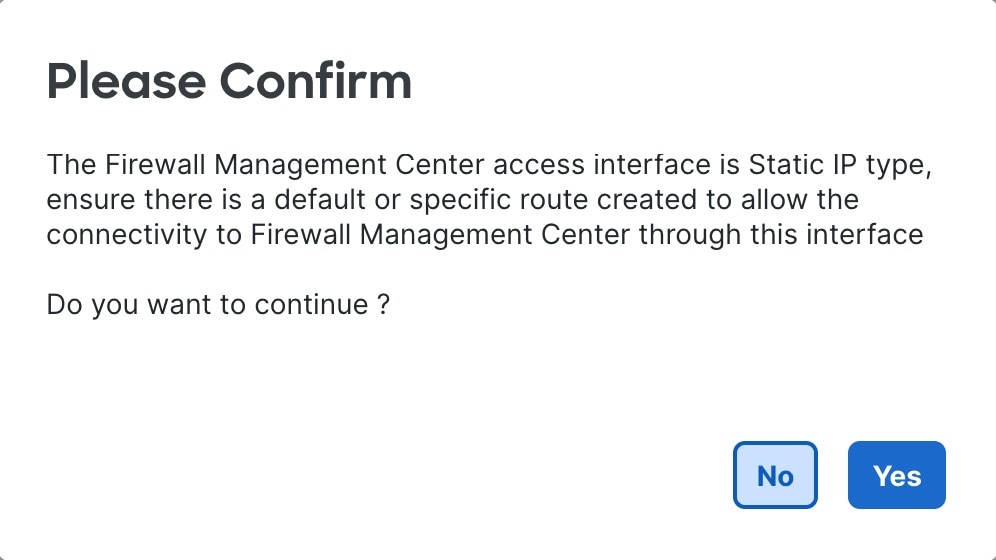
  3. If you use a static IP address, you are reminded to make sure you have a default route. Click Yes.

  4. Click OK to exit the interface.

  5. Click Save on the Interfaces page.

Step 4

If you only want to change the IP address:

  1. Change the IP address.

  2. For a static IP address, you are reminded to make sure you have a default route. Click Yes.

  3. Click OK to exit the interface.

  4. Click Save on the Interfaces page.

Step 5

Click the Routing tab, click Static Route, and then add or change the default or static route for the manager access interface.

Step 6

Deploy configuration changes.

The Cloud-Delivered Firewall Management Center will deploy the configuration changes over the current connection. After the deployment, the data interface will have a new IP address, so the management connection will need to be reestablished.

Step 7

Update the Hostname or IP Address in the Cloud-Delivered Firewall Management Center.

Step 8

Ensure the management connection is reestablished.

In the Device area, against the Management field, click Manager Access Details: Configuration and then click Connection Status.

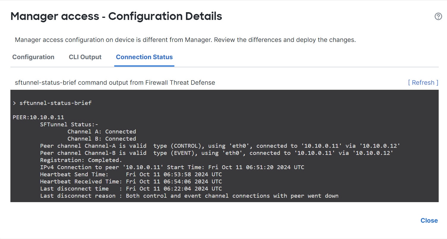
The following status shows a successful connection for a data interface, showing the internal "tap_nlp" interface.

Figure 26. Connection status
The status indicates a successful connection for the internal "tap_nlp" data interface in the GUI.

If it takes more than 10 minutes to reestablish the connection, you should troubleshoot the connection. See Troubleshoot Management Connectivity on a Data Interface.


Update the Hostname or IP Address in the Cloud-Delivered Firewall Management Center

This task allows you to manually update the hostname or IP address on the managing Cloud-Delivered Firewall Management Center when device network settings have been modified outside of the management interface.

If you edit the hostname or IP address of a device after you added it to the Cloud-Delivered Firewall Management Center (using the device's CLI, for example), you need to use this procedure to manually update the hostname or IP address on the managing Cloud-Delivered Firewall Management Center.

To change the device management IP address on the device, see Modify Firewall Threat Defense management interface settings at the CLI.

If you used only the NAT ID when registering the device, then the IP shows as NO-IP on this page, and you do not need to update the IP address/hostname.

If you used zero-touch provisioning to register the device on the outside interface, the hostname is automatically generated along with a matching DDNS configuration. You cannot edit the hostname in this case.

Procedure

Step 1

Choose Devices > Device Management.

Step 2

Next to the device where you want to modify management options, click Edit (edit icon).

Step 3

Click Device and view the Management area.

Step 4

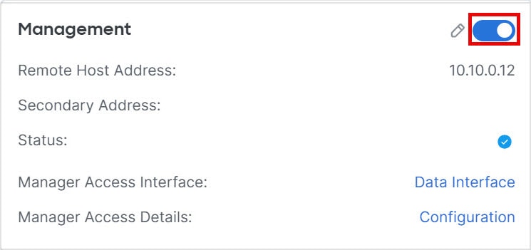
Disable management temporarily by clicking the slider so it is disabled Slider disabled (slider disabled).

Figure 27. Disable management
Disable Management

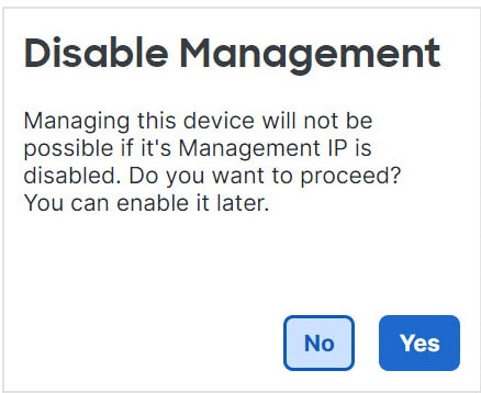
You are prompted to proceed with disabling management; click Yes.

The image illustrates the prompt for disabling management, highlighting the option to click "Yes" to proceed with blocking the connection between the device and the management interface.

Disabling management blocks the connection between the Cloud-Delivered Firewall Management Center and the device, but does not unregister the device from the Cloud-Delivered Firewall Management Center.

Step 5

Edit the Remote Host Address IP address and optional Secondary Address (when using a redundant data interface) or hostname by clicking Edit (edit icon).

Figure 28. Edit management address
Edit Management Address

Step 6

In the Management dialog box, modify the name or IP address in the Remote Host Address field and the optional Secondary Address field. Click Save.

For information about using a secondary manager access data interface, see Configure a redundant manager access data interface.

Figure 29. Management IP address
Management IP Address

Step 7

Reenable management by clicking the slider so it is enabled Slider enabled (slider enabled).

Figure 30. Enable management connection
Enable Management Connection

Change the Cloud-Delivered Firewall Management Center IP Address

This task ensures the Cloud-Delivered Firewall Management Center IP address or hostname matches between the management center and device CLI, maintaining consistent configurations and network resiliency.

If you change the Cloud-Delivered Firewall Management Center IP address or hostname, you should also change the value at the device CLI so the configurations match. Although in most cases, the management connection will be reestablished without changing the Cloud-Delivered Firewall Management Center IP address or hostname on the device, in at least one case, you must perform this task for the connection to be reestablished: when you added the device to the Cloud-Delivered Firewall Management Center and you specified the NAT ID only. Even in other cases, we recommend keeping the Cloud-Delivered Firewall Management Center IP address or hostname up to date for extra network resiliency.

Procedure

Step 1

Change the Cloud-Delivered Firewall Management Center IP address.

Caution


Be careful when making changes to the Cloud-Delivered Firewall Management Center interface to which you are connected; if you cannot re-connect because of a configuration error, you need to access the Cloud-Delivered Firewall Management Center console port to re-configure the network settings in the Linux shell. You must contact Cisco TAC to guide you in this operation.

  1. Choose System (system gear icon) > Configuration > Management Interfaces.

  2. In the Interfaces area, click Edit next to the interface that you want to configure.

  3. Change the IP address, and click Save.

Step 2

At the Firewall Threat Defense CLI, view the Cloud-Delivered Firewall Management Center identifier.

show managers

Example:

> show managers
Type                      : Manager
Host                      : 10.10.1.4
Display name              : 10.10.1.4
Identifier                : f7ffad78-bf16-11ec-a737-baa2f76ef602
Registration              : Completed
Management type           : Configuration
 

Step 3

At the Firewall Threat Defense CLI, edit the Cloud-Delivered Firewall Management Center IP address or hostname.

configure manager edit identifier {hostname {ip_address | hostname} | displayname display_name}

If the Cloud-Delivered Firewall Management Center was originally identified by DONTRESOLVE and a NAT ID, you can change the value to a hostname or IP address using this command. You cannot change an IP address or hostname to DONTRESOLVE .

The management connection will go down, and then reestablish. You can monitor the state of the connection using the sftunnel-status command.

Example:

> configure manager edit f7ffad78-bf16-11ec-a737-baa2f76ef602 hostname 10.10.5.1


Change both Cloud-Delivered Firewall Management Center and Threat Defense IP addresses

You might want to change both Cloud-Delivered Firewall Management Center and Firewall Threat Defense IP addresses if you need to move them to a new network.

Procedure

Step 1

Disable the management connection.

For a high-availability pair or cluster, perform these steps on all units.

  1. Choose Devices > Device Management .

  2. Next to the device, click Edit (edit icon) .

  3. Click Device , and view the Management area.

  4. Disable management temporarily by clicking the slider so it is disabled (slider disabled) .

    Figure 31. Disable Management
    Disable Management

    You are prompted to proceed with disabling management; click Yes .

Step 2

Change the device IP address in the Cloud-Delivered Firewall Management Center to the new device IP address.

You will change the IP address on the device later.

For a high-availability pair or cluster, perform these steps on all units.

  1. Edit the Remote Host Address IP address and optional Secondary Address (when using a redundant data interface) or hostname by clicking Edit (edit icon) .

    Figure 32. Edit Management Address
    Edit Management Address
  2. In the Management dialog box, modify the name or IP address in the Remote Host Address field and the optional Secondary Address field , and click Save .

    Figure 33. Management IP Address
    Management IP Address

Step 3

Change the Cloud-Delivered Firewall Management Center IP address.

Caution


Be careful when making changes to the Cloud-Delivered Firewall Management Center interface to which you are connected. If you cannot re-connect because of a configuration error, you need to access the Cloud-Delivered Firewall Management Center console port to re-configure the network settings in the Linux shell. You must contact Cisco TAC to guide you in this operation.

  1. Choose System (system gear icon) > Configuration > Management Interfaces .

  2. In the Interfaces area, click Edit next to the interface that you want to configure.

  3. Change the IP address, and click Save .

Step 4

Change the manager IP address on the device.

For a high-availability pair or cluster, perform these steps on all units.

  1. At the Firewall Threat Defense CLI, view the Cloud-Delivered Firewall Management Center identifier.

    show managers

    Example:
    > show managers
    Type                      : Manager
    Host                      : 10.10.1.4
    Display name              : 10.10.1.4
    Identifier                : f7ffad78-bf16-11ec-a737-baa2f76ef602
    Registration              : Completed
    Management type           : Configuration
  2. Edit the Cloud-Delivered Firewall Management Center IP address or hostname.

    configure manager edit identifier { hostname { ip_address | hostname } | displayname display_name }

    If the Cloud-Delivered Firewall Management Center was originally identified by DONTRESOLVE and a NAT ID, you can change the value to a hostname or IP address using this command. You cannot change an IP address or hostname to DONTRESOLVE .

    Example:
    
                                    > configure manager edit f7ffad78-bf16-11ec-a737-baa2f76ef602 
                                    hostname 
                                    10.10.5.1
                                

Step 5

Change the IP address of the manager access interface at the console port.

For a high-availability pair or cluster, perform these steps on all units.

If you use the dedicated Management interface:

configure network ipv4

configure network ipv6

If you use the dedicated Management interface:

configure network management-data-interface disable

configure network management-data-interface

Step 6

Re-enable management by clicking the slider (slider enabled) .

For a high-availability pair or cluster, perform these steps on all units.

Figure 34. Enable Management Connection
Enable Management Connection

Step 7

(If you use a data interface for manager access) Refresh the data interface settings in the Cloud-Delivered Firewall Management Center .

For a high-availability pair, perform this step on both units.

  1. Choose Devices > Device Management , and click Manager Access - Configuration Details , and then click Refresh .

  2. Choose Devices > Device Management , and click the Interfaces tab and set the IP address to match the new address.

  3. Return to the Manager Access - Configuration Details dialog box, and click Acknowledge to remove the deployment block.

Step 8

Ensure the management connection is reestablished.

In the Cloud-Delivered Firewall Management Center , check the management connection status. Navigate to the Devices > Device Management , and click Management section under the Device tab. Then, click Manager Access - Configuration Details to view the Connection Status page.

At the Firewall Threat Defense CLI, enter the sftunnel-status-brief command to view the management connection status.

This status indicates a successful connection for a data interface and displays the internal "tap_nlp" interface.

Figure 35. Connection Status
Connection Status

Step 9

(For a high-availability Cloud-Delivered Firewall Management Center pair) Repeat configuration changes on the secondary Cloud-Delivered Firewall Management Center .

  1. Change the secondary Cloud-Delivered Firewall Management Center IP address.

  2. Specify the new peer addresses on both units.

  3. Make the secondary unit the active unit.

  4. Disable the device management connection.

  5. Change the device IP address in the Cloud-Delivered Firewall Management Center .

  6. Re-enable the management connection.


Change the manager access interface

After you register the device, you can change the manager access interface between the Management interface and a data interface.

Change the manager access interface from management to data

You can manage the Firewall Threat Defense from either the dedicated management interface or from a data interface. If you want to change the manager access interface after you added the device to the Cloud-Delivered Firewall Management Center , follow these steps to migrate from the Management interface to a data interface. To migrate the other direction, refer to Change the manager access interface from data to management .

When you initiate the manager access migration from management to data, the Cloud-Delivered Firewall Management Center applies a block on deployment to the Firewall Threat Defense. To remove the block, enable manager access on the data interface.

Before you begin

For high-availability pairs, unless stated otherwise, perform all steps only on the active unit. After deploying the configuration changes, the standby unit synchronizes configuration and other state information from the active unit.

Procedure

Step 1

Initiate the interface migration.

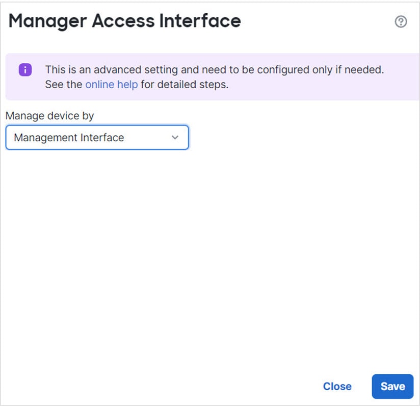
  1. On the Devices > Device Management page, click Edit (edit icon) for the device. Click Device , and in the Management area, click the Manager Access Interface link.

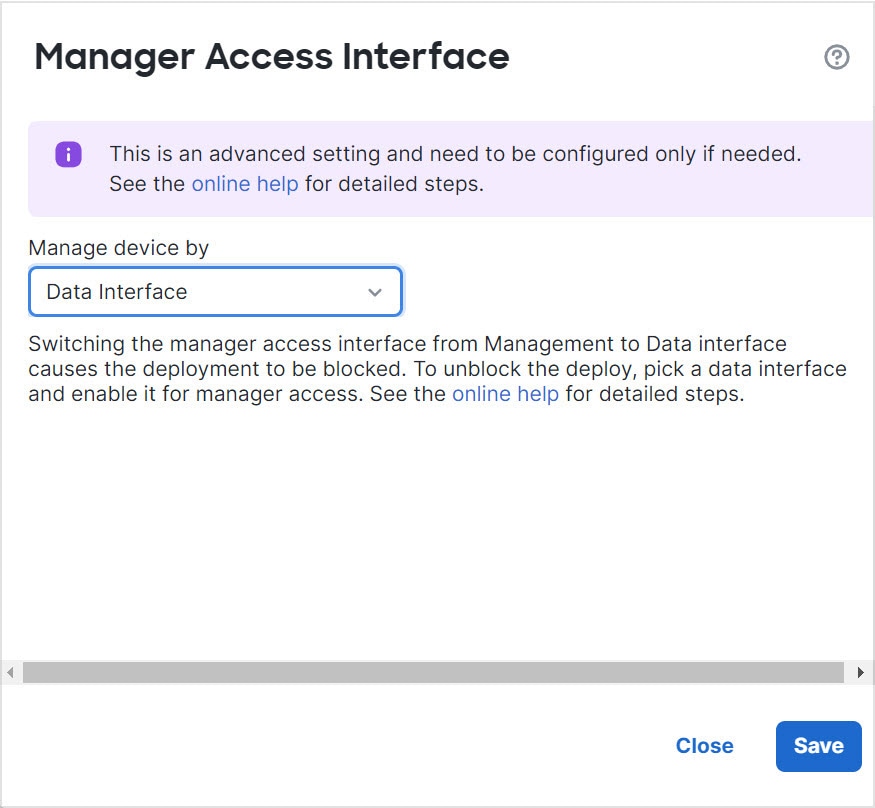
    The Manager Access Interface field shows the current Management interface. When you click the link, choose the new interface type, Data Interface , in the Manage device by drop-down list.

    Figure 36. Manager Access Interface
    Manager Access Interface
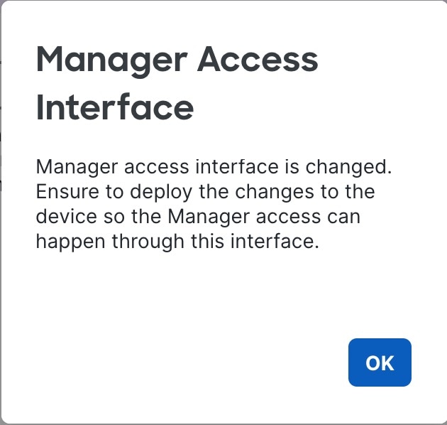
  2. Click OK and then Close .

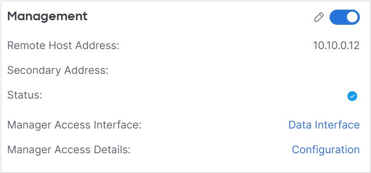
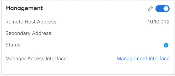
    You must now complete the remaining steps in this procedure to enable manager access on the data interface. The Management area now shows Manager Access Interface: Data Interface , and Manager Access Details: Configuration .

    Figure 37. Manager Access
    Manager Access

    If you click Configuration , the Manager Access - Configuration Details dialog box opens. The Manager Access Mode shows a Deploy pending state.

Step 2

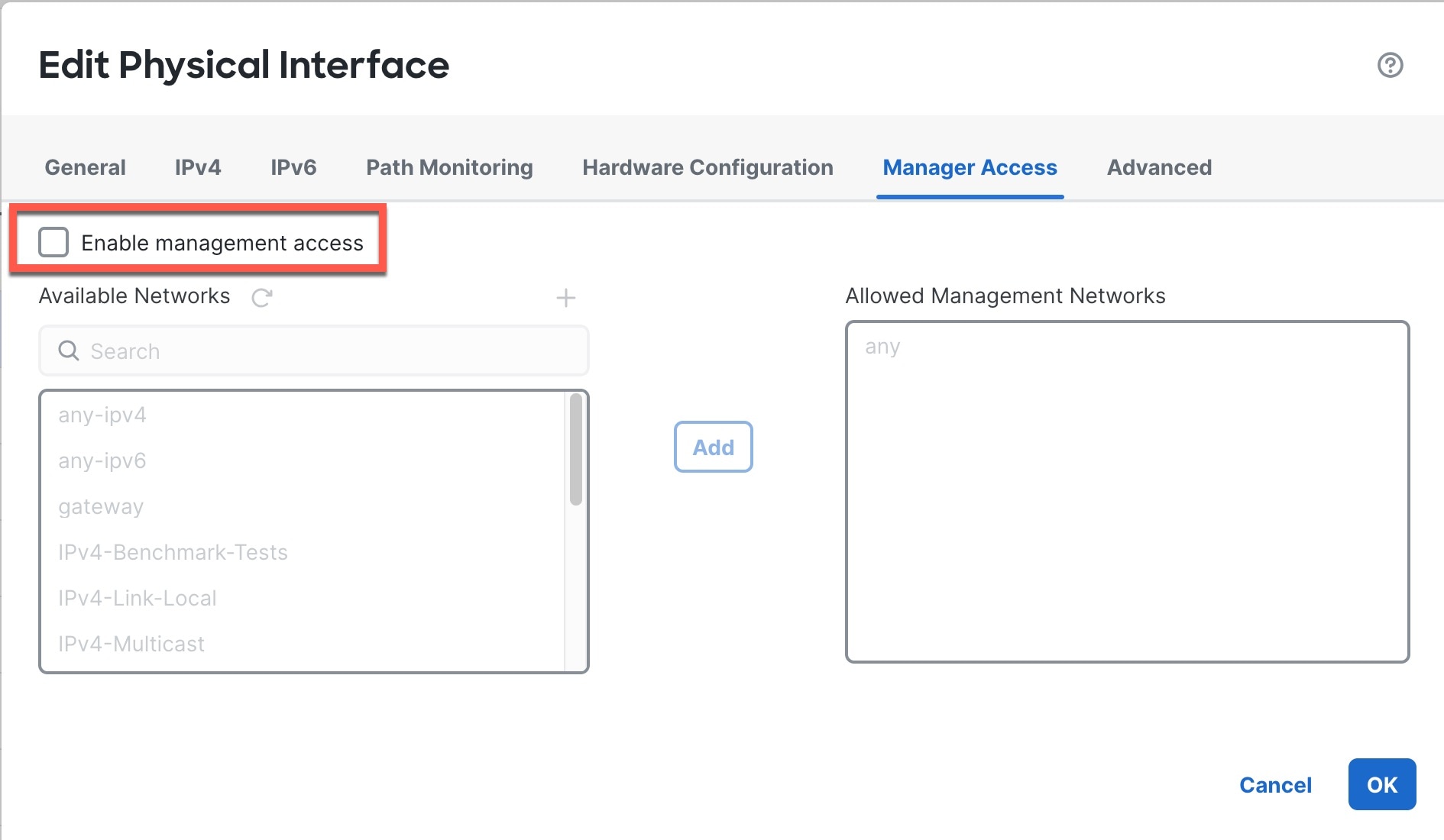
Enable manager access on the data interface (s) . Click Interfaces , click Edit (edit icon) for the interface, and then click Manager Access .

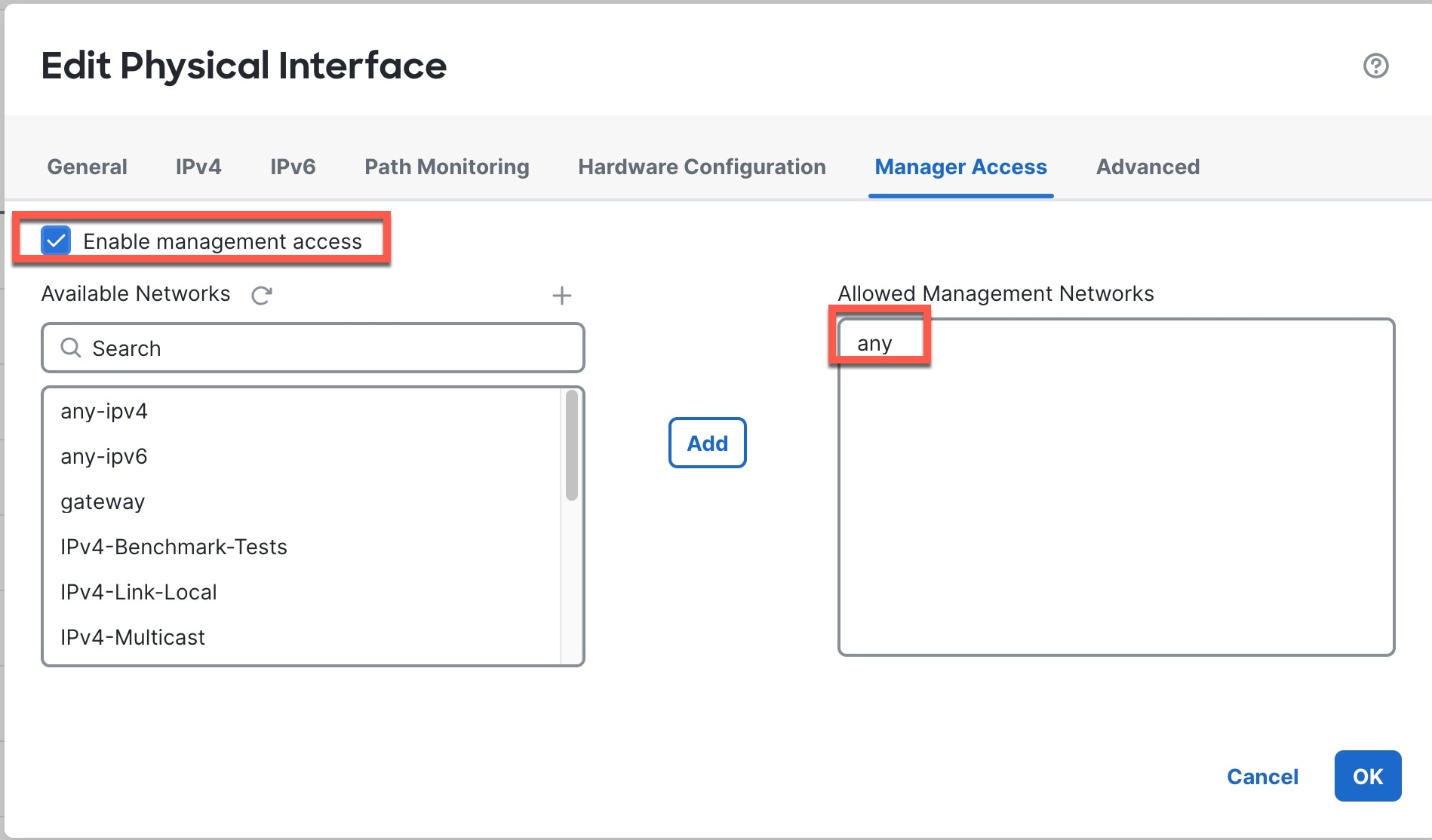
Check Enable management access and click OK . By default, all networks are allowed, but you can limit access as long as the Cloud-Delivered Firewall Management Center address is allowed.

If the manager access interface uses a static IP address, you are reminded to configure routing for it.

Click Save on the Interfaces page. See Configure routed mode interfaces for more information about interface settings. You can enable manager access on one routed data interface , plus an optional secondary interface . Make sure these interfaces are fully configured with a name and IP address and that they are enabled.

If you use a secondary interface for redundancy, see Configure a redundant manager access data interface for additional required configuration.

Step 3

(Optional) If you use DHCP for the interface, enable the web type DDNS method on the DDNS page. Navigate to Devices > Device Management , and then click DDNS under the DHCP tab.

See Configure Dynamic DNS . DDNS ensures the Cloud-Delivered Firewall Management Center can reach the Firewall Threat Defense at its Fully-Qualified Domain Name (FQDN) if the FTD's IP address changes.

Step 4

Make sure the Firewall Threat Defense can route to the Cloud-Delivered Firewall Management Center through the data interface. Add a static route if necessary on the Static Route page. Navigate to Devices > Device Management and then click Static Route under the Routing tab.

See Add a Static Route .

Step 5

(Optional) Configure DNS in a Platform Settings policy: choose Devices > Platform Settings , and click DNS . Apply the policy to this device.

See Configure DNS server settings . DNS is required if you use DDNS. You may also use DNS for FQDNs in your security policies.

Step 6

(Optional) Enable SSH for the data interface in a Platform Settings policy, and apply it to this device at Devices > Device Management page. Click Edit (edit icon) for the device and then click SSH Access .

See Configure secure shell SSH access . SSH is not enabled by default on the data interfaces, so if you want to manage the Firewall Threat Defense using SSH, you need to explicitly allow it.

Step 7

Deploy configuration changes.

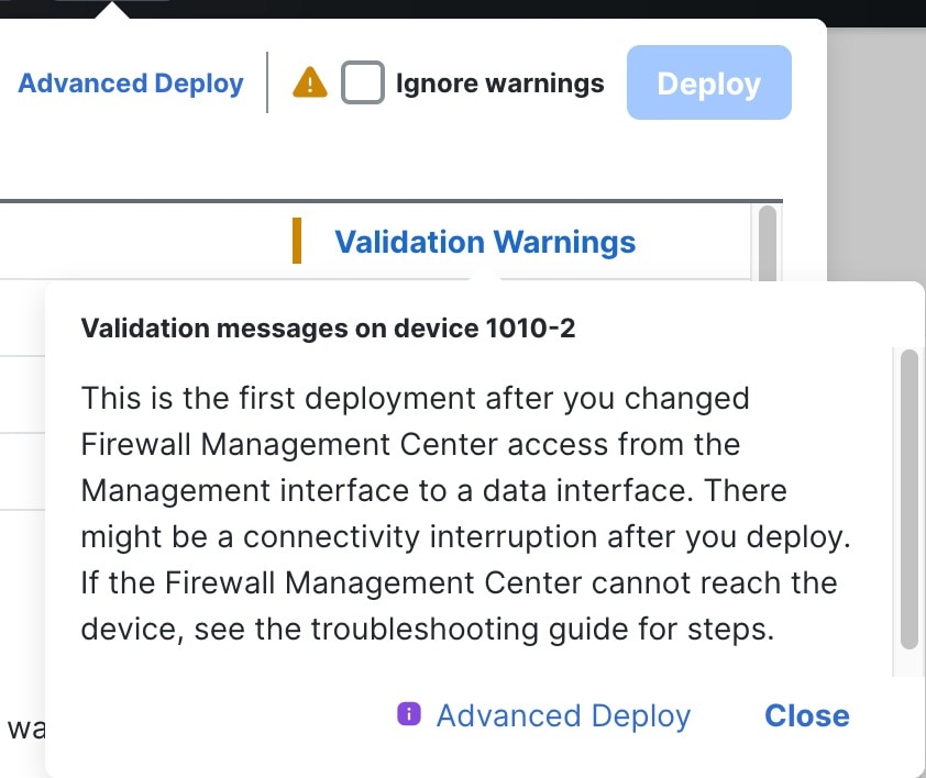
You will see a validation error to confirm that you are changing the manager access interface. Check Ignore warnings and deploy again.

The Cloud-Delivered Firewall Management Center will deploy the configuration changes over the current Management interface. After the deployment, the data interface is now ready for use, but the original management connection to Management is still active.

Step 8

After deployment, perform these actions.

  1. At the Firewall Threat Defense CLI (preferably from the console port), set the Management interface to use a static IP address and set the gateway to use the data interfaces. For high availability, perform this step on both units.


                                configure network 
                                {
                                ipv4
                                 | 
                                ipv6
                                } 
                                manual
                                ip_address netmask
                                data-interfaces
                             
                        
    • ip_address netmask —Although you do not plan to use the Management interface, you must set a static IP address, for example, a private address so that you can set the gateway to data-interfaces (see the next bullet). You cannot use DHCP because the default route, which must be data-interfaces , might be overwritten with one received from the DHCP server.

    • data-interfaces —This setting forwards management traffic over the backplane so it can be routed through the manager access data interface.

    We recommend that you use the console port instead of an SSH connection because when you change the Management interface network settings, your SSH session will be disconnected.

  2. If necessary, re-cable the Firewall Threat Defense so it can reach the Cloud-Delivered Firewall Management Center on the data interface. For high availability, perform this step on both units.

  3. In the Cloud-Delivered Firewall Management Center, disable the management connection for the Firewall Threat Defense in the Devices > Device Management page in the Management area under the Device tab, and then re-enable the connection.

Step 9

Ensure the management connection is reestablished.

In the Devices > Device Management page, click Manager Access Details: Configuration and then click Connection Status .

Alternatively, you can check at the Firewall Threat Defense CLI. Enter the sftunnel-status-brief command to view the management connection status.

This status indicates a successful connection for a data interface, showing the internal "tap_nlp" interface.

Figure 38. Connection Status
Connection Status

If it takes more than 10 minutes to reestablish the connection, you should troubleshoot the connection. See Troubleshoot Management Connectivity on a Data Interface .


Change the manager access interface from data to management

This task enables you to migrate manager access from a data interface to the dedicated management interface, allowing you to manage the Firewall Threat Defense through the Management interface instead of a data interface.

You can manage the Firewall Threat Defense from either the dedicated management interface or from a data interface. If you want to change the manager access interface after you added the device to the Cloud-Delivered Firewall Management Center, follow these steps to migrate from a data interface to the management interface. To migrate the other direction, see Change the manager access interface from management to data.

Initiating the manager access migration from data to management causes the Cloud-Delivered Firewall Management Center to apply a block on deployment to the Firewall Threat Defense. You must disable manager access on the data interface to remove the block.

Before you begin

For high-availability pairs, unless stated otherwise, perform all steps only on the active unit. Once the configuration changes are deployed, the standby unit synchronizes configuration and other state information from the active unit.

Follow these steps to disable manager access on a data interface, and also configure other required settings.

Procedure

Step 1

Initiate the interface migration.

  1. On the Devices > Device Management page, click Edit (edit icon) for the device. Click Device, and in the Management area, click the link for Manager Access Interface.

    The Manager Access Interface field shows the current management interface as data. When you click the link, choose the new interface type, Management Interface, in the Manage device by drop-down list.

    Figure 39. Manager access interface
    Manager Access Interface
  2. Click Save.

    Click OK and then Close.

    You must now complete the remaining steps in this procedure to enable manager access on the Management interface. The Management area now shows the Manager Access Interface: Management Interface.

    Figure 40. Manager access
    Manager Access

Step 2

Disable manager access on the data interface(s). Click Interfaces, click Edit (edit icon) for the interface, and then click Manager Access.

Uncheck Enable management access and click OK. Click Save on the Interfaces page. This step removes the block on deployment.

Step 3

If you have not already done so, configure DNS settings for the data interface in a Platform Setting policy, and apply it to this device at Devices > Device Management page. Click Edit (edit icon) for the device and then click DNS.

See Configure DNS server settings. The Cloud-Delivered Firewall Management Center deployment that disables manager access on the data interface will remove any local DNS configuration. If that DNS server is used in any security policy, such as an FQDN in an Access Rule, then you must re-apply the DNS configuration using the Cloud-Delivered Firewall Management Center.

Step 4

Deploy configuration changes.

The Cloud-Delivered Firewall Management Center will deploy the configuration changes over the current data interface.

Step 5

If necessary, re-cable the Firewall Threat Defense so it can reach the Cloud-Delivered Firewall Management Center on the Management interface. For High Availability, perform this step on both units.

Step 6

At the Firewall Threat Defense CLI, configure the Management interface IP address and gateway using a static IP address or DHCP. For high availability, perform this step on both units.

When you originally configured the data interface for manager access, the Management gateway was set to data-interfaces, which forwarded management traffic over the backplane so it could be routed through the manager access data interface. You now need to set an IP address for the gateway on the management network.

Static IP address:

configure network {ipv4 | ipv6} manual ip_address netmask gateway_ip

DHCP:

configure network{ipv4 | ipv6} DHCP

Step 7

In the Cloud-Delivered Firewall Management Center, disable the management connection for the Firewall Threat Defense in the Devices > Device Management, Management section under Device tab, and then reenable the connection.

Step 8

Ensure the management connection is reestablished.

In the Cloud-Delivered Firewall Management Center, check the management connection status on the Devices > Device Management, Management section under Device tab, Status field or view notifications in the Cloud-Delivered Firewall Management Center.

At the Firewall Threat Defense CLI, enter the sftunnel-status-brief command to view the management connection status.

If it takes more than 10 minutes to reestablish the connection, you should troubleshoot the connection. See Troubleshoot Management Connectivity on a Data Interface.


Troubleshoot the management connection

This reference provides information to help diagnose and resolve management connection issues.

Manually Roll Back the configuration if the Cloud-Delivered Firewall Management Center loses Connectivity

Use this task to restore management connectivity when a configuration change deployed from the Cloud-Delivered Firewall Management Center affects network connectivity and you need to roll back to the last-deployed configuration.

If you use a data interface on the Firewall Threat Defense for manager access and deploy a configuration change from the Cloud-Delivered Firewall Management Center that affects network connectivity, you can roll back the configuration on the Firewall Threat Defense to the last-deployed configuration to restore management connectivity. Afterward, update the configuration settings in Cloud-Delivered Firewall Management Center to maintain network connectivity, and re-deploy. You can use the rollback feature even if you do not lose connectivity; it is not limited to this troubleshooting situation.

Alternatively, you can enable auto rollback of the configuration if you lose connectivity after a deployment; see Edit deployment settings.

See these guidelines:

  • Only the previous deployment is available locally on the Firewall Threat Defense; you cannot roll back to any earlier deployments.

  • Rollback is supported for high availability but not supported for clustering deployments.

  • Rollback is not supported immediately after high availability creation.

  • The rollback only affects configurations that you can set in the Cloud-Delivered Firewall Management Center. For example, the rollback does not affect any local configuration related to the dedicated Management interface, which you can only configure at the Firewall Threat Defense CLI. Note that if you changed data interface settings after the last Cloud-Delivered Firewall Management Center deployment using the configure network management-data-interface command, and then you use the rollback command, those settings will not be preserved; they will roll back to the last-deployed Cloud-Delivered Firewall Management Center settings.

  • UCAPL/CC mode cannot be rolled back.

  • Out-of-band SCEP certificate data that was updated during the previous deployment cannot be rolled back.

  • During the rollback, connections will drop because the current configuration will be cleared.

Procedure

Step 1

At the Firewall Threat Defense CLI, roll back to the previous configuration.

configure policy rollback

Note


For a high availability pair, this command is allowed only on the active unit.

After the rollback, the Firewall Threat Defense notifies the Cloud-Delivered Firewall Management Center about the successful completion. The deployment screen In the Cloud-Delivered Firewall Management Center displays a banner indicating that the configuration was rolled back.

Note


If the rollback fails and the Cloud-Delivered Firewall Management Center management is restored, refer to https://www.cisco.com/c/en/us/support/docs/security/firepower-ngfw-virtual/215258-troubleshooting-firepower-threat-defense.html for common deployment problems. In some cases, the rollback may fail after the Cloud-Delivered Firewall Management Center management access is restored. Resolve any Cloud-Delivered Firewall Management Center configuration issues and redeploy from the Cloud-Delivered Firewall Management Center.

Example:
For the Firewall Threat Defense that uses a data interface for manager access:

> configure policy rollback

The last deployment to this FTD was on June 1, 2020 and its status was Successful.
Do you want to continue [Y/N]?

Y

Rolling back complete configuration on the FTD. This will take time.
.....................
Policy rollback was successful on the FTD.
Configuration has been reverted back to transaction id: 
Following is the rollback summary:
...................
....................
>
Example:
For Firewall Threat Defenses in a high availability pair that use a data interface for Cloud-Delivered Firewall Management Center access:

> configure policy rollback

Checking Eligibility ....
============= DEVICE DETAILS =============
Device Version: 7.2.0
Device Type: FTD
Device Mode: Offbox
Device in HA: true
Is HA disabled: false
HA state: active - standby ready
==========================================
Device is eligible for policy rollback
Do you want to continue [YES/NO]?

YES

Starting rollback...
    Preparing policy configuration on the device.           Status: success
    Applying updated policy configuration on the device.    Status: success
    Applying Lina File Configuration on the device.         Status: success
    Applying Lina Configuration on the device.              Status: success
    Commit Lina Configuration.                              Status: success
    Commit Lina File Configuration.                         Status: success
    Commit Lina File Configuration.                         Status: success
=================================================================
POLICY ROLLBACK STATUS: SUCCESS
=================================================================
>

Step 2

Check that the management connection was reestablished.

In Cloud-Delivered Firewall Management Center, check the management connection status on the Connection Status page. Navigate to Devices > Device Management and then navigate to Management area under the Devices tab. Then in the Manager Access - Configuration Details screen, click Connection Status.

At the Firewall Threat Defense CLI, enter the sftunnel-status-brief command to view the management connection status.

If it takes more than 10 minutes to reestablish the connection, you should troubleshoot the connection. See Troubleshoot Management Connectivity on a Data Interface.


Troubleshoot Management Connectivity on a Data Interface

This topic helps you troubleshoot the loss of management connectivity when using a data interface for manager access instead of the dedicated Management interface.

If you use a data interface for manager access instead of the dedicated Management interface, exercise caution when changing the interface and network settings for the Firewall Threat Defense in the Cloud-Delivered Firewall Management Center to avoid disrupting the connection. If you change the management interface type after adding the Firewall Threat Defense to the Cloud-Delivered Firewall Management Center (switching between data and Management interfaces), misconfiguration of interfaces and network settings can result in loss of management connectivity.

Use the following methods to troubleshoot management connectivity:

  • View management connection status: Check the status in the Devices > Device Management page or use sftunnel-status-brief at the CLI.

  • View network information: Use show network to verify Management and manager access data interface settings.

  • Check registration: Use show managers to confirm registration completion.

  • Ping the manager: Use ping or ping system to test connectivity.

  • Capture packets: Use capture on the nlp_int_tap interface to trace management traffic.

  • Check interface status: Use show interface detail for the nlp_int_tap interface.

  • Check routing and NAT: Use show route and show nat to verify routing and internal NAT rules.

  • Check DDNS: Use debug ddns and related commands to verify DDNS updates.


        > sftunnel-status-brief
        PEER:10.10.17.202
        Registration: Completed.
        Connection to peer '10.10.17.202' Attempted at Mon Jun 15 09:21:57 2020 UTC
        Last disconnect time : Mon Jun 15 09:19:09 2020 UTC
        Last disconnect reason : Both control and event channel connections with peer went down
      

        > show network
        ===============[ System Information ]===============
        Hostname                  : FTD-4
        Domains                   : cisco.com
        DNS Servers               : 72.163.47.11
        DNS from router           : enabled
        Management port           : 8305
        IPv4 Default route
        Gateway                 : data-interfaces
        ...
      

Note


At the Firewall Threat Defense CLI, check that the Cloud-Delivered Firewall Management Center registration was completed. Note that this command will not show the current status of the management connection.


Refer to https://cisco.com/go/fmc-reg-error for Cloud-Delivered Firewall Management Center log file information.

Troubleshoot management connectivity on a data interface in a High Availability pair

This topic provides troubleshooting steps for management connectivity issues on data interfaces in High Availability, covering scenarios involving interface connectivity failures and ISP changes.

The management connection between the active peer and the Security Cloud Control can be disrupted due to the following reasons:

  • Connectivity issues on the data interface that is used for management on the active unit.

  • Change in internet service provider (ISP).

Follow these procedures to restore connectivity based on the identified cause:

  • Connectivity issues: Manually fail over to the standby unit and configure a new data interface for Security Cloud Control access.

  • ISP change: Manually update the new network details on the active unit using CLI commands to restore device connectivity.

Data management interface on active unit has connectivity issues
  1. In Security Cloud Control , manually switch the active unit to standby. See Switch the Active Peer in the Firewall Threat Defense High Availability Pair .

    As an alternative, you can run the no failover active command on the active unit.

  2. Next to the device high-availability pair you want to edit, click Edit ( ).

  3. Choose Routing > Static Route and delete the static route defined for the old data management interface.

  4. Click the Interfaces tab to remove the old interface configuration and configure the new data management interface.


    Note


    Before removing the old data management interface information, remember the details if you want to use the same information.


  5. Click the High Availability tab to update the Monitored Interfaces and Standby IP Address for the new interface.

  6. Click Save and add the static route for the new data management interface under Routing > Static Route .

  7. Deploy configuration changes. .

  8. Re-cable the FTD when deployment reaches 90 percent so the Security Cloud Control reaches the device on the new interface.


    Note


    After you re-cable, the deployment may fail if it timed out before re-establishing the management connection to the new interface. In that case, you must reinitiate the deployment after re-cabling for a successful deployment.


  9. Verify the management connection status in Cloud-Delivered Firewall Management Center or via the sftunnel-status-brief command at the FTD CLI.

Internet service provider has changed

If you have changed your ISP, you can lose management connectivity, even though High Availability health is normal. Configure the new network details of the management interface using the CLI commands.


Note


These commands are available only on the active unit and not on standby.


For information about the Firewall Threat Defense CLI, see the FTD command reference .

  1. Connect to the device CLI and log in with the Admin username and password.

  2. Use the configure network management-data-interface commands to update the IPv4 address, netmask, or gateway.

    Example:

    
                Configure network management-data-interface ipv4 manual 10.10.6.7 255.255.255.0 interface gig0/0
                Configuration updated successfully..!!
              

    Note


    All other CLI commands of configure network management-data-interface are not supported on devices in a High Availability pair.


  3. Verify the connection using sftunnel-status-brief .

  4. In Security Cloud Control , navigate to Security Devices > FTD, select the device, and click Refresh in the FMC Access Details pane.

  5. Click Acknowledge to remove the deployment block and reconcile the configuration changes.

View inventory details

The Inventory Details section of the Device page shows chassis details such as the CPU and memory.

Figure 41. Inventory details
Inventory Details

This section shows the chassis serial number. The firewall includes two serial numbers: the chassis serial number and the PCB (circuit board) serial number. The PCB serial number is shown in the System section. The Firewall Threat Defense Virtual does not have a chassis serial number.


Note


For physical Firewall Threat Defense devices, the Memory field in Inventory Details shows only the data plane memory, not the total system memory.


To update information, click Refresh (refresh icon).

Edit applied policies

This task allows you to assign or modify policies for an individual firewall device, including access control policies and other security policies that govern device behavior.

The Applied Policies section of the Device page displays the following policies applied to your firewall:

Figure 42. Applied policies
Applied Policies

For policies with links, you can click the link to view the policy.

For the Access Control Policy, view the Access Policy Information for Troubleshooting dialog box by clicking the Exclamation (exclamation icon) icon. This dialog box shows how access rules are expanded into access control entries (ACEs).

Figure 43. Access policy information for troubleshooting
Access Policy Information for Troubleshooting

Procedure


Step 1

Choose Devices > Device Management.

Step 2

Next to the device where you want to assign policies, click Edit (edit icon).

Step 3

Click Device.

Step 4

In the Applied Policies section, click Edit (edit icon).

Figure 44. Policy assignments
Policy Assignments

Step 5

For each policy type, choose a policy from the drop-down menu. Only existing policies are listed.

Step 6

Click Save.


What to do next

  • Deploy configuration changes.

Edit advanced settings

The Advanced Settings section of the Device page displays a table of advanced configuration settings, as described below. You can edit any of these settings.

Table 5. Advanced settings table fields

Field

Description

Application Bypass

The state of Automatic Application Bypass on the device.

Bypass Threshold

The Automatic Application Bypass threshold, in milliseconds.

Object Group Search

The state of object group search on the device. While operating, the FTD device expands access control rules into multiple access control list entries based on the contents of any network or interface objects used in the access rule. You can reduce the memory required to search access control rules by enabling object group search. With object group search enabled, the system does not expand network or interface objects, but instead searches access rules for matches based on those group definitions. Object group search does not impact how your access rules are defined or how they appear in Firepower Management Center. It impacts only how the device interprets and processes them while matching connections to access control rules.

Note


By default, the Object Group Search is enabled when you add threat defense for the first time in the management center.

Interface Object Optimization

The state of interface object optimization on the device. During deployment, interface groups and security zones used in the access control and prefilter policies generate separate rules for each source/destination interface pair. If you enable interface object optimization, the system will instead deploy a single rule per access control/prefilter rule, which can simplify the device configuration and improve deployment performance. If you select this option, also select the Object Group Search option to reduce memory usage on the device.

These topics explain how to edit the advanced device settings.


Note


For information about the Transfer Packets setting, see Edit general settings.


Configure automatic application bypass

Automatic Application Bypass (AAB) enables packet processing to continue when Snort detection becomes unavailable or exceeds processing time limits. This feature ensures network traffic flow continuity while providing diagnostic information for troubleshooting detection engine failures.

Automatic Application Bypass (AAB) allows packets to bypass detection if Snort is down or, for a Classic device, if a packet takes too long to process. AAB causes Snort to restart within ten minutes of the failure, and generates troubleshooting data that can be analyzed to investigate the cause of the Snort failure.


Caution


AAB activation partially restarts the Snort process, which temporarily interrupts the inspection of a few packets.Whether traffic drops during this interruption or passes without further inspection depends on how the assigned device handles traffic. Refer to Snort restart traffic behavior.


Note the following behavior:

Firewall Threat Defense Behavior: If Snort is down, then AAB is triggered after the specified timer duration. If Snort is up, then AAB is never triggered, even if packet processing exceeds the configured timer.

Classic Device Behavior: AAB limits the time allowed to process packets through an interface. You balance packet processing delays with your network's tolerance for packet latency.

The feature functions with any deployment; however, it is most valuable in inline deployments.

Typically, you use Rule Latency Thresholding in the intrusion policy to fast-path packets after the latency threshold value is exceeded. Rule Latency Thresholding does not shut down the engine or generate troubleshooting data.

If detection is bypassed, the device generates a health monitoring alert.

By default the AAB is disabled; to enable AAB follow these steps:

Procedure


Step 1

Choose Devices > Device Management.

Step 2

Next to the device where you want to edit advanced device settings, click Edit (edit icon).

Step 3

Click Device, then click Edit (edit icon) in the Advanced Settings section.

Step 4

Check Automatic Application Bypass.

Step 5

Enter a Bypass Threshold from 250 ms to 60,000 ms. The default setting is 3000 milliseconds (ms).

Step 6

Click Save.


What to do next

  • Deploy configuration changes.

Configure object group search

This task enables object group search on a Firewall Threat Defense device to reduce memory requirements for access control policies that include network or interface objects.

While operating, the Firewall Threat Defense device expands access control rules into multiple access control list entries based on the contents of any network or interface objects used in the access rule. You can reduce the memory required to search access control rules by enabling object group search. With object group search enabled, the system does not expand network or interface objects, but instead searches access rules for matches based on those group definitions. Object group search does not impact how your access rules are defined or how they appear in Cloud-Delivered Firewall Management Center. It impacts only how the device interprets and processes them while matching connections to access control rules.

Enabling object group search reduces memory requirements for access control policies that include network or interface objects. However, it is important to note that object group search might also decrease rule lookup performance and thus increase CPU utilization. You should balance the CPU impact against the reduced memory requirements for your specific access control policy. In most cases, enabling object group search provides a net operational improvement.

By default, the object group search is enabled for the threat defense devices that are added for the first time in the Cloud-Delivered Firewall Management Center. In the case of upgraded devices, if the device is configured with disabled object group search, then you need to manually enable it. You can enable it on one device at a time; you cannot enable it globally. We recommend that you enable it on a device to which you deploy access rules that use network or interface objects.


Note


  • If you enable object group search and then configure and operate the device for a while, be aware that subsequently disabling the feature might lead to undesirable results.

  • When you disable object group search, your existing access control rules will be expanded in the device's running configuration. If the expansion requires more memory than is available on the device, your device can be left in an inconsistent state and you might see a performance impact.

  • If your device is operating normally, do not disable the object group search after you have enabled it.


Before you begin

  • Model support—Firewall Threat Defense

  • We recommend that you also enable transactional commit on each device. From the device CLI, enter the asp rule-engine transactional-commit access-group command.

  • Changing this setting can be disruptive to system operation while the device recompiles the ACLs. We recommend that you change this setting during a maintenance window.

  • You can use FlexConfig to configure the object-group-search threshold command to enable a threshold to help prevent performance degradation. When operating with a threshold, for each connection, both the source and destination IP addresses are matched against network objects. If the number of objects matched by the source address times the number matched by the destination address exceeds 10,000, the connection is dropped. Configure your rules to prevent an excessive number of matches.

Follow these steps to configure object group search:

Procedure


Step 1

Choose Devices > Device Management.

Step 2

Next to the Firewall Threat Defense device where you want to configure the rule, click the Edit (edit icon).

Step 3

Click the Device tab, then click the Edit (edit icon) in the Advanced Settings section.

Step 4

Check Object Group Search.

Step 5

To have object group search work on interface objects in addition to network objects, check Interface Object Optimization.

If you do not select Interface Object Optimization, the system deploys separate rules for each source/interface pair, rather that use the security zones and interface groups used in the rules. This means the interface groups are not available for object group search processing.

Step 6

Click Save.


Configure interface object optimization

Interface object optimization enables the system to deploy a single rule per access control/prefilter rule instead of generating separate rules for each source/destination interface pair, simplifying device configuration and improving deployment performance.

During deployment, interface groups and security zones used in the access control and prefilter policies generate separate rules for each source and destination interface pair. Enabling interface object optimization deploys a single rule per access control or prefilter rule. This approach simplifies device configuration and can improve deployment performance. If you select this option, also select the Object Group Search option to reduce evice memory usage.

Interface object optimization is disabled by default. You can enable it on one device at a time; you cannot enable it globally.


Note


If you disable interface object optimization, the system deploys existing access control rules without using interface objects. This process might take longer. If object group search is enabled, its benefits do not apply to interface objects, and the device's running configuration might show expanded access control rules. If this expansion requires more memory than is available, the device can become inconsistent, which may affect performance


Before you begin

Model support—Firewall Threat Defense

Procedure


Step 1

Choose Devices > Device Management.

Step 2

Next to the Firewall Threat Defense device where you want to configure the rule, click the Edit (edit icon).

Step 3

Under the Device tab, click Edit (edit icon) in the Advanced Settings section.

Step 4

Check Interface Object Optimization.

Step 5

Click Save.


Edit deployment settings

Configure the deployment settings to enable auto rollback of the deployment if the management connection fails as a result of the deployment. For example, if you use data for management center access and then you misconfigure the data interface.

The Deployment Settings section of the Device page displays information for managing automatic rollback configuration. As an alternative, you can manually roll back the configuration using the configure policy rollback command (see Manually Roll Back the configuration if the Cloud-Delivered Firewall Management Center loses Connectivity).

Figure 45. Deployment settings
Deployment Settings
Table 6. Deployment settings

Field

Description

Auto Rollback Deployment if Connectivity Fails

Enabled or Disabled.

You can enable auto rollback if the management connection fails as a result of the deployment; specifically if you use data for management center access, and then you misconfigure the data interface.

Connectivity Monitor Interval (in Minutes)

Shows the amount of time to wait before rolling back the configuration.

Consider the following guidelines:

  • Only the previous deployment is available locally on the Firewall Threat Defense; you cannot roll back to any earlier deployments.

  • Rollback is supported for high availability but not supported for clustering deployments.

  • Rollback is not supported immediately after high availability creation.

  • The rollback only affects configurations that you can set in the Cloud-Delivered Firewall Management Center. For example, the rollback does not affect any local configuration related to the dedicated Management interface, which you can only configure at the Firewall Threat Defense CLI. Note that if you changed data interface settings after the last Cloud-Delivered Firewall Management Center deployment using the configure network management-data-interface command, and then you use the rollback command, those settings will not be preserved; they will roll back to the last-deployed Cloud-Delivered Firewall Management Center settings.

  • UCAPL/CC mode cannot be rolled back.

  • Out-of-band SCEP certificate data that was updated during the previous deployment cannot be rolled back.

  • During the rollback, connections will drop because the current configuration will be cleared.

Procedure


Step 1

Choose Devices > Device Management.

Step 2

Next to the device where you want to assign policies, click Edit (edit icon).

Step 3

Click Device.

Step 4

In the Deployment Settings section, click Edit (edit icon).

Figure 46. Deployment settings
Deployment Settings

Step 5

Check Auto Rollback Deployment if Connectivity Fails to enable auto rollback.

Step 6

Set the Connectivity Monitor Interval (in minutes) to configure the wait time before rolling back the configuration. The default is 20 minutes.

Step 7

If a rollback occurs, consider these next steps.

  • If the auto rollback was successful, you see a success message instructing you to do a full deployment.

  • Go to Deploy > Advanced Deploy page and click the Preview (preview icon) icon to view the parts of the configuration that were rolled back (see Deploy configuration changes).

    To view the changes, click Show Rollback Changes.

    To hide the changes, click Hide Rollback Changes.

    Figure 47. Rollback changes
    Hide Rollback Changes
  • In the Deployment History Preview, you can view the rollback changes. See View deployment history.

Step 8

Verify that the management connection was reestablished.

  1. In Cloud-Delivered Firewall Management Center, check the management connection status on the connection status page.

  2. Navigate to Devices > Device Management and then in Management area under the Devices tab, click Connection Status to view the Connection Status page.

  3. At the Firewall Threat Defense CLI, enter the sftunnel-status-brief command to view the management connection status.

If it takes more than 10 minutes to reestablish the connection, troubleshoot the connection. See Troubleshoot Management Connectivity on a Data Interface.


Edit cluster health monitor settings

This task allows you to modify cluster health monitor settings to control how cluster nodes monitor system health and automatically rejoin the cluster after failures.

The Cluster Health Monitor Settings section of the Cluster page displays the settings for monitoring cluster node health. You can monitor any port-channel ID, any single physical interface ID, and the Snort and disk-full processes. Health monitoring is not performed on VLAN subinterfaces or virtual interfaces such as VNIs or BVIs. You cannot configure monitoring for the cluster control link. It is always monitored.

When a topology change occurs (such as adding or removing a data interface, enabling or disabling an interface on the node or the switch, or adding an additional switch to form a VSS or vPC or VNet) you should disable the system health check feature. Also, disable interface monitoring for any interfaces that are disabled. When the topology change is complete, and the configuration change is synced to all nodes, you can re-enable the system health check feature and monitored interfaces.

Procedure


Step 1

Choose Devices > Device Management.

Step 2

Next to the cluster you want to modify, click Edit (edit icon).

Step 3

Click Cluster.

Step 4

In the Cluster Health Monitor Settings section, click Edit (edit icon).

Step 5

Disable the system health check by clicking the Health Check slider.

Figure 48. Disable the system health check
Disable the System Health Check

When any topology changes occur (such as adding or removing a data interface, enabling or disabling an interface on the node or the switch, or adding an additional switch to form a VSS or vPC or VNet) you should disable the system health check feature and also disable interface monitoring for the disabled interfaces. When the topology change is complete, and the configuration change is synced to all nodes, you can re-enable the system health check feature and monitored interfaces.

Step 6

Configure the hold time and interface debounce time.

  • Hold Time—Set the hold time to determine the amount of time between node heartbeat status messages, between 0.3 and 45 seconds. The default is 3 seconds.

  • Interface Debounce Time—Set the debounce time between 300 and 9000 ms. The default is 500 ms. Lower values allow for faster detection of interface failures. Note that configuring a lower debounce time increases the chances of false-positives. When an interface status update occurs, the node waits the specified number of milliseconds before marking the interface as failed and removing the node from the cluster. If an EtherChannel transitions from a down state to an up state, such as after the switch reloads or enables an EtherChannel, a longer debounce time can prevent the interface from appearing failed on a cluster node if another cluster node bundles the ports more quickly.

Step 7

Customize the auto-rejoin cluster settings after a health check failure.

Figure 49. Configure Auto-Rejoin settings
Configure Auto-Rejoin Settings

Set values for the Cluster Interface, Data Interface, and System (internal failures include: application sync timeout; inconsistent application statuses; and so on):

  • Attempts—Sets the number of rejoin attempts, between -1 and 65535. 0 disables auto-rejoining. The default for the Cluster Interface is -1 (unlimited). The default for the Data Interface and System is 3.

  • Interval Between Attempts—Defines the interval duration in minutes between rejoin attempts, between 2 and 60. The default value is 5 minutes. The maximum total time that the node attempts to rejoin the cluster is limited to 14400 minutes (10 days) from the time of last failure.

  • Interval Variation—Defines if the interval duration increases. Set the value between 1 and 3: 1 (no change); 2 (2 x the previous duration), or 3 (3 x the previous duration). For example, if you set the interval duration to 5 minutes, and set the variation to 2, then the first attempt is after 5 minutes; the 2nd attempt is 10 minutes (2 x 5); the 3rd attempt 20 minutes (2 x 10), and so on. The default value is 1 for the Cluster Interface and 2 for the Data Interface and System.

Step 8

Configure monitored interfaces by moving interfaces in the Monitored Interfaces or Unmonitored Interfaces window. You can also check or uncheck Enable Service Application Monitoring to enable or disable monitoring of the Snort and disk-full processes.

Figure 50. Configure monitored interfaces
Configure Monitored Interfaces

The interface health check monitors for link failures. If all physical ports for a given logical interface fail on a particular node, but there are active ports under the same logical interface on other nodes, then the node is removed from the cluster. The time required to remove a member from the cluster depends on the type of interface and whether the node is established or is joining the cluster. By default, health check is enabled for all interfaces and the Snort and disk-full processes.

You might want to disable health monitoring of non-essential interfaces.

When any topology changes occur (such as adding or removing a data interface, enabling or disabling an interface on the node or the switch, or adding an additional switch to form a VSS or vPC or VNet) you should disable the system health check feature and also disable interface monitoring for the disabled interfaces. When the topology change is complete, and the configuration change is synced to all nodes, you can re-enable the system health check feature and monitored interfaces.

Step 9

Click Save.

Deploy configuration changes.


Hot swap an SSD

Hot swapping SSDs allows you to maintain system operation while replacing faulty drives, removing drives, or adding drives to form a RAID configuration.

If you have two SSDs, they form a RAID when you boot up. You can perform the following tasks at the Firewall Threat Defense CLI while the firewall is powered up:

  • Hot swap one of the SSDs—If an SSD is faulty, you can replace it. Note that if you only have one SSD, you cannot remove it while the firewall is powered on.

  • Remove one of the SSDs—If you have two SSDs, you can remove one.

  • Add a second SSD—If you have one SSD, you can add a second SSD and form a RAID.

    When you use only one SSD in Secure Firewall devices, the Drive State will show as degraded.


Caution


Do not remove an SSD without first removing it from the RAID using this procedure. You can cause data loss.


Procedure


Step 1

Remove one of the SSDs.

  1. Remove the SSD from the RAID.

    configure RAID remove-secure local-disk {1 | 2}

    The remove-secure keyword removes the SSD from the RAID, disables the self-encrypting disk feature, and performs a secure erase of the SSD. If you only want to remove the SSD from the RAID and want to keep the data intact, you can use the remove keyword.

    Example:

    
    > configure raid remove-secure local-disk 2
    
    
  2. Monitor the RAID status until the SSD no longer shows in the inventory.

    show RAID

    After the SSD is removed from the RAID, the Operability and Drive State will show as degraded. The second drive will no longer be listed as a member disk.

    Example:

    
    > show raid
    Virtual Drive
    ID:                         1
    Size (MB):                  858306
    Operability:                operable
    Presence:                   equipped
    Lifecycle:                  available
    Drive State:                optimal
    Type:                       raid
    Level:                      raid1
    Max Disks:                  2
    Meta Version:               1.0
    Array State:                active
    Sync Action:                idle
    Sync Completed:             unknown
    Degraded:                   0
    Sync Speed:                 none
    
    RAID member Disk:
    Device Name:                nvme0n1
    Disk State:                 in-sync
    Disk Slot:                  1
    Read Errors:                0
    Recovery Start:             none
    Bad Blocks:
    Unacknowledged Bad Blocks:   
    
    Device Name:                nvme1n1
    Disk State:                 in-sync
    Disk Slot:                  2
    Read Errors:                0
    Recovery Start:             none
    Bad Blocks:
    Unacknowledged Bad Blocks:   
    
    > show raid
    Virtual Drive
    ID:                         1
    Size (MB):                  858306
    Operability:                degraded
    Presence:                   equipped
    Lifecycle:                  available
    Drive State:                degraded
    Type:                       raid
    Level:                      raid1
    Max Disks:                  2
    Meta Version:               1.0
    Array State:                active
    Sync Action:                idle
    Sync Completed:             unknown
    Degraded:                   1
    Sync Speed:                 none
    
    RAID member Disk:
    Device Name:                nvme0n1
    Disk State:                 in-sync
    Disk Slot:                  1
    Read Errors:                0
    Recovery Start:             none
    Bad Blocks:
    Unacknowledged Bad Blocks:   
    
    
  3. Physically remove the SSD from the chassis.

Step 2

Add an SSD.

  1. Physically add the SSD to the empty slot.

  2. Add the SSD to the RAID.

    configure RAID add local-disk {1 | 2}

    It can take several hours to complete syncing the new SSD to the RAID, during which the firewall is completely operational. You can even reboot, and the sync will continue after it powers up. Use the show RAID command to show the status.

    If you install an SSD that was previously used on another system, and is still locked, enter the following command:

    configure RAID add local-disk {1 | 2} psid

    The psid is printed on the label attached to the back of the SSD. Alternatively, you can reboot the system, and the SSD will be reformatted and added to the RAID.


Disable the USB port

This reference explains how to disable the USB port functionality on the device for security or operational requirements.

By default, the type-A USB port is enabled. You might want to disable USB port access for security purposes. Disabling USB is supported on these models:

  • Firepower 1000 Series

  • Secure Firewall 200 Series

  • Secure Firewall 3100

  • Secure Firewall 4200

Guidelines

  • Enabling or disabling the USB port requires a reboot .

  • If the USB port is disabled and you downgrade to a version that does not support this feature, the port will remain disabled, and you cannot re-enable it without erasing the NVRAM (the FXOS local-mgmt erase secure all command).

  • If you perform a ROMMON factory-reset or FXOS local-mgmt erase secure , the USB port will be re-enabled.

  • For high availability or clustering , you must disable or re-enable the port individually on each unit.


Note


This feature does not affect the USB console port, if present.


Disable the USB port on a device

Disable the USB port on a device to enhance security by preventing unauthorized data transfer or malicious USB device connections.

To disable the USB port on a device, you can do so at the Firewall Threat Defense CLI.

Procedure


Step 1

Disable the USB port.

system support USB configure disable

reboot

To re-enable the USB port, enter system support USB configure enable .

Example:


>system support usb configure disable
USB Port Admin State set to 'disabled'.
Please reboot the system to apply any control state changes.

>reboot
This command will reboot the system. Continue?
Please enter 'YES' or 'NO': YES

Step 2

View the port status.

system support USB show

The Admin State shows the USB port configuration. The Oper State shows the current operation. For example, if you disable the USB port but do not reload, the Admin State will show disabled while the Oper State would be enabled.

Example:


>system support usb show
USB Port Info
---------------
Admin State: disabled
Oper State: disabled

Disable the USB port in multi-instance mode

This task allows you to control USB port access on your device by enabling or disabling the port through the FXOS CLI.

To disable the USB port in multi-instance mode, you can do so at the FXOS CLI.

Procedure


Step 1

Disable the USB port and reboot for the change to take effect.

  1. Disable the USB port.

    scope fabric-interconnect

    disable USB-port

    commit buffer

  2. Reboot the chassis.

    connect local-mgmt

    reboot

Example:


firepower-4245 /fabric-interconnect # disable usb-port
Note: USB enablement or disablement changes are effected only after FXOS reboot.
Confirm change? (yes/no) [yes]:
device /fabric-interconnect* # commit buffer
Note: USB enablement or disablement changes are effected only after FXOS reboot.
Confirm change? (yes/no) [yes]:yes
firepower-4245 /fabric-interconnect # connect local-mgmt
firepower-4245(local-mgmt)# reboot
Before rebooting, please take a configuration backup.
Do you still want to reboot? (yes/no):yes
Broadcast message from admin@firepower-4245 (Wed Feb 21 05:59:55 2024):
All shells being terminated due to system /sbin/reboot

Step 2

Enable the USB port and reboot for the change to take effect.

  1. Enable the USB port.

    scope fabric-interconnect

    enable USB-port

    commit buffer

  2. Reboot the chassis.

    connect local-mgmt

    reboot

Example:


firepower-4245 /fabric-interconnect # enable usb-port
Note: USB enablement or disablement changes are effected only after FXOS reboot.
Confirm change? (yes/no) [yes]:
device /fabric-interconnect* # commit buffer
Note: USB enablement or disablement changes are effected only after FXOS reboot.
Confirm change? (yes/no) [yes]:yes
firepower-4245 /fabric-interconnect # connect local-mgmt
firepower-4245(local-mgmt)# reboot
Before rebooting, please take a configuration backup.
Do you still want to reboot? (yes/no):yes
Broadcast message from admin@firepower-4245 (Wed Feb 21 05:59:55 2024):
All shells being terminated due to system /sbin/reboot

Step 3

View the USB port status.

scope fabric-interconnect

show USB-port

The Admin State shows the USB port configuration. The Oper State shows the current operation. For example, if you disable the USB port but do not reload, the Admin State will show Disabled while the Oper State would will Enabled.

Example:


firepower-4245# scope fabric-interconnect
firepower-4245 /fabric-interconnect # show usb-port
Usb Port:
Equipment         Admin State Oper State
---------------- -----------  ----------
A                 Disabled    Disabled


Configure SNMP for FXOS

You can configure the Simple Network Management Protocol (SNMP) for the underlying FXOS operating system that controls low-level chassis functions. For SNMP for the Firewall Threat Defense, see Configure SNMP for a security device.

SNMP is an application-layer protocol that provides a message format for communication between SNMP managers and agents. SNMP provides a standardized framework and a common language used for the monitoring and management of devices in a network.

The SNMP framework consists of three parts:

  • An SNMP manager—The system used to control and monitor the activities of network devices using SNMP.

  • An SNMP agent—The software component within the chassis that maintains the data for the chassis and reports the data, as needed, to the SNMP manager. The chassis includes the agent and a collection of MIBs. To enable the SNMP agent and create the relationship between the manager and agent, enable and configure SNMP in the Cloud-Delivered Firewall Management Center.

  • A managed information base (MIB)—The collection of managed objects on the SNMP agent.

The chassis supports SNMPv1, SNMPv2c and SNMPv3. Both SNMPv1 and SNMPv2c use a community-based form of security. SNMPv3 uses username and password for security.

Enable SNMP for FXOS

Enable SNMP and configure settings.

Procedure


Step 1

Choose Devices > Device Management.

Step 2

Click SNMP.

Step 3

Complete the following fields:

Name Description

Admin State check box

Whether SNMP is enabled or disabled. Enable this service only if your system includes integration with an SNMP server.

Port field

The port on which the Firepower chassis communicates with the SNMP host. You cannot change the default port.

Community field

The default SNMPv1 or v2 community name or SNMP v3 username and password that the Firepower chassis includes on any trap messages it sends to the SNMP host.

Enter a valid community string for SNMPv1 and SNMPv2:

  • Alphanumeric string between 1 and 32 characters and special characters ! (exclamation), - (hyphen), ~ (tilde), && (double ampersand), [ ] (square brackets), ^ (carat), ' (single quote), " (double quotes), and < > (angle brackets).

  • Do not use @ (at sign), \ (backslash), ? (question mark) or an empty space.

  • The string can also be in ASCII characters ranging 0x21 to 0x7E inclusive, excluding HTML interjection vectors, namely single quote ('), double quotes ("), and angle brackets (< >).

Enter a valid username and password for SNMPv3:

  • Username can be alphanumeric string and can include @ (at sign), \ (backslash), . (period), _ (underscore), and - (hyphen).

  • The password restrictions are same as the community string restrictions.

Note that if the Community field is already set, the text to the right of the empty field reads Set: Yes. If the Community field is not yet populated with a value, the text to the right of the empty field reads Set: No.

System Admin Name field

The contact person responsible for the SNMP implementation.

Enter a string of up to 255 characters, such as an email address or a name and telephone number.

Location field

The location of the host on which the SNMP agent (server) runs.

Enter an alphanumeric string up to 510 characters.

Step 4

Click Save.


What to do next

Create SNMP traps and users.

Create an SNMP Trap for FXOS

Create traps for SNMP.

Procedure


Step 1

Choose Devices > Device Management.

Step 2

Click SNMP.

Step 3

In the SNMP Traps Configuration area, click Add.

Step 4

In the SNMP Trap Configuration dialog box, complete the following fields:

Name Description

Host Name field

The hostname or IP address of the SNMP host to which the Firepower chassis should send the trap.

Community field

The SNMP v1 or v2 community name or the SNMP v3 username the Firepower chassis includes when it sends the trap to the SNMP host. This must be the same as the community or username that is configured for the SNMP service.

Enter an alphanumeric string between 1 and 32 characters. Do not use @ (at sign), \ (backslash), " (double quote), ? (question mark) or an empty space.

Port field

The port on which the Firepower chassis communicates with the SNMP host for the trap.

Enter an integer between 1 and 65535.

Version field

The SNMP version and model used for the trap. This can be one of the following:

  • V1

  • V2

  • V3

Type field

If you select V2 or V3 for the version, the type of trap to send. This can be one of the following:

  • Traps

  • Informs

Privilege field

If you select V3 for the version, the privilege associated with the trap. This can be one of the following:

  • Auth—Authentication but no encryption

  • Noauth—No authentication or encryption

  • Priv—Authentication and encryption

Step 5

Click OK to close the SNMP Trap Configuration dialog box.

Step 6

Click Save.


Create an SNMP user for FXOS

Create SNMP users.

Procedure


Step 1

Choose Devices > Device Management.

Step 2

Click SNMP.

Step 3

In the SNMP Users Configuration area, click Add.

Step 4

In the SNMP User Configuration dialog box, complete the following fields:

Name Description

Username field

The username assigned to the SNMP user.

Enter up to 32 letters or numbers. The name must begin with a letter and you can also specify _ (underscore), . (period), @ (at sign), and - (hyphen).

Auth Algorithm Type field

The authorization type: SHA.

Use AES-128 checkbox

If checked, this user uses AES-128 encryption.

Note


SNMPv3 does not support DES. If you leave the AES-128 box unchecked, no privacy encryption will be done and any configured privacy password will have no effect.

Authentication Password field

The password for the user.

Confirm field

The password again for confirmation purposes.

Encryption Password field

The privacy password for the user.

Confirm field

The privacy password again for confirmation purposes.

Step 5

Click OK to close the SNMP User Configuration dialog box.

Step 6

Click Save.


Configure alarms for the ISA 3000

You can configure the alarm system on a Cisco ISA 3000 device to alert you when undesirable conditions occur.

About alarms

You can configure the ISA 3000 to issue alarms for a variety of conditions. If any conditions do not match the configured settings, the system triggers an alarm, which is reported by way of LEDs, syslog messages, SNMP traps, and through external devices connected to the alarm output interface. By default, triggered alarms issue syslog messages only.

You can configure the alarm system to monitor the following:

  • Power supply.

  • Primary and secondary temperature sensors.

  • Alarm input interfaces.

The ISA 3000 has internal sensors plus two alarm input interfaces and one alarm output interface. You can connect external sensors, such as door sensors, to the alarm inputs. You can connect external alarm devices, such as buzzers or lights, to the alarm output interface.

The alarm output interface is a relay mechanism. Depending on the alarm conditions, the relay is either energized or de-energized. When it is energized, any device connected to the interface is activated. A de-energized relay results in the inactive state of any connected devices. The relay remains in an energized state as long as alarms are triggered.

For information about connecting external sensors and the alarm relay, Refer to Alarms for the Cisco ISA 3000 chapter in Cisco ASA Series General Operations CLI Configuration Guide. see Cisco ISA 3000 Industrial Security Appliance Hardware Installation Guide.

Alarm input interfaces

You can connect the alarm input interfaces (or contacts) to external sensors, such as one that detects if a door is open.

Each alarm input interface has a corresponding LED. These LEDs convey the alarm status of each alarm input. You can configure the trigger and severity for each alarm input. In addition to the LED, you can configure the contact to trigger the output relay (to activate an external alarm), to send syslog messages, and to send SNMP traps.

The following table explains the statuses of the LEDs in response to alarm conditions for the alarm inputs. It also explains the behavior for the output relay, syslog messages, and SNMP traps, if you enable these responses to the alarm input.

Alarm Status

LED

Output Relay

Syslog

SNMP Trap

Alarm not configured

Off

—

—

—

No alarms triggered

Solid green

—

—

—

Alarm activated

Minor alarm—solid red

Major alarm—flashing red

Relay energized

Syslog generated

SNMP trap sent

Alarm end

Solid green

Relay de-energized

Syslog generated

—

Alarm output interface

You can connect an external alarm, such as a buzzer or light, to the alarm output interface.

The alarm output interface functions as a relay and also has a corresponding LED, which conveys the alarm status of an external sensor connected to the input interface, and internal sensors such as the dual power supply and temperature sensors. You configure which alarms should activate the output relay, if any.

The following table explains the statuses of the LEDs and output relay in response to alarm conditions. It also explains the behavior for syslog messages, and SNMP traps, if you enable these responses to the alarm.

Alarm Status

LED

Output Relay

Syslog

SNMP Trap

Alarm not configured

Off

—

—

—

No alarms triggered

Solid green

—

—

—

Alarm activated

Solid red

Relay energized

Syslog generated

SNMP trap sent

Alarm end

Solid green

Relay de-energized

Syslog generated

—

Syslog alarms

By default, the system sends syslog messages when any alarm is triggered. You can disable syslog messaging if you do not want the messages.

For syslog alarms to work, you must also enable diagnostic logging. Choose Devices > Platform Settings, add or edit a Threat Defense platform settings policy that is assigned to the device, and configure destinations and settings on the Syslog page. For example, you can configure a syslog server, console logging, or internal buffer logging.

Without enabling a destination for diagnostic logging, the alarm system has nowhere to send syslog messages.

SNMP Alarms

You can optionally configure the alarms to send SNMP traps to your SNMP server. For SNMP trap alarms to work, you must also configure SNMP settings.

Choose Devices > Platform Settings, add or edit a Threat Defense platform settings policy that is assigned to the device, and enable SNMP and configure settings on the SNMP page.

Defaults for alarms

The following table specifies the defaults for alarm input interfaces (contacts), redundant power supply, and temperature.

Alarm

Trigger

Severity

SNMP Trap

Output Relay

Syslog Message

Alarm Contact 1

Enabled

Closed State

Minor

Disabled

Disabled

Enabled

Alarm Contact 2

Enabled

Closed State

Minor

Disabled

Disabled

Enabled

Redundant Power Supply (when enabled)

Enabled

—

—

Disabled

Disabled

Enabled

Temperature

Enabled for the primary temperature alarm (default values of 92°C and -40°C for the high and low thresholds respectively)

Disabled for the secondary alarm.

—

—

Enabled for primary temperature alarm

Enabled for primary temperature alarm

Enabled for primary temperature alarm

Prerequisites for alarms

Model support

Firewall Threat Defense on the ISA 3000.

Configure alarms for the ISA 3000

You use FlexConfig to configure alarms for the ISA 3000. The following topics explain how to configure the different types of alarms.

Configure alarm input contacts

If you connect the alarm input contacts (interfaces) to external sensors, you can configure the contacts to issue alarms based on the input from the sensor. In fact, the contacts are enabled by default to send syslog messages if the contact is closed, that is, if the electrical current stops flowing through the contact. You need to configure the contact only if the defaults do not meet your requirements.

The alarm contacts are numbered 1 and 2, so you need to understand how you have wired the physical pins to configure the correct settings. You configure the contacts separately.

Procedure

Step 1

Create the FlexConfig object to configure the alarm input contacts.

  1. Choose Objects > Object Management > FlexConfig > FlexConfig Object.

  2. Click Add FlexConfig Object, configure the following properties, and click Save.

    • Name—The object name. For example, Configure_Alarm_Contacts.

    • Deployment—Select Everytime. You want this configuration to be sent in every deployment to ensure it remains configured.

    • Type—Keep the default, Append. The commands are sent to the device after the commands for directly-supported features.

    • Object body—In the object body, type the commands needed to configure the alarm contacts. The following steps explain the commands.

  3. Configure a description for the alarm contact.

    alarm contact {1 | 2} description string

    For example, to set the description of contact 1 to "Door Open," enter the following:

    
    alarm contact 1 description Door Open 
    
  4. Configure the severity for the alarm contact.

    alarm contact {1 | 2 | any} severity {major | minor | none}

    Instead of configuring one contact, you can specify any to change the severity for all contacts. The severity controls the behavior of the LED associated with the contact.

    • major —The LED blinks red.

    • minor—The LED is solid red. This is the default.

    • none—The LED is off.

    For example, to set the severity of contact 1 to Major, enter the following:

    
    alarm contact 1 severity major 
    
  5. Configure the trigger for the alarm contact.

    alarm contact {1 | 2 | any} trigger {open | closed}

    Instead of configuring one contact, you can specify any to change the trigger for all contacts. The trigger determines the electrical condition that signals an alert.

    • open —The normal condition for the contact is closed, that is, the electrical current is running through the contact. An alert is triggered if the contact becomes open, that is, the electrical current stops flowing.

    • closed —The normal condition for the contact is open, that is, the electrical current does not run through the contact. An alert is triggered if the contact becomes closed, that is, the electrical current starts running through the contact. This is the default.

    For example, you connect a door sensor to alarm input contact 1, and its normal state has no electrical current flowing through the alarm contact (it is open). If the door is opened, the contact is closed and electrical current flows through the alarm contact. You would set the alarm trigger to closed so that the alarm goes off when the electrical current starts flowing.

    
    alarm contact 1 trigger closed 
    
  6. Configure the actions to take when the alarm contact is triggered.

    alarm facility input-alarm {1 | 2} {relay | syslog | notifies}

    You can configure more than one action. For example, you can configure the device to activate the external alarm, send syslog messages, and also send SNMP traps.

    • relay—Energize the alarm output relay, which activates the external alarm that you attached to it, such as a buzzer or a flashing light. The output LED also goes red.

    • syslog—Send a syslog message. This option is enabled by default.

    • notifies—Send an SNMP trap.

    For example, to enable all actions for the alarm input contact 1, enter the following:

    
    alarm facility input-alarm 1 relay 
    alarm facility input-alarm 1 syslog
    alarm facility input-alarm 1 notifies
    
  7. Verify that the object body contains the commands you want.

    For example, if your template includes all of the command examples shown in this procedure, the object body would have the following commands:

    
    alarm contact 1 description Door Open
    alarm contact 1 severity major 
    alarm contact 1 trigger closed 
    alarm facility input-alarm 1 relay 
    alarm facility input-alarm 1 syslog
    alarm facility input-alarm 1 notifies
    

    The object body should look similar to the following:


    FlexConfig object for configuring alarm contacts on ISA 3000 devices.

  8. Click Save.

Step 2

Create the FlexConfig policy and assign it to the devices.

  1. Choose Devices > FlexConfig.

  2. Either click New Policy, or if an existing FlexConfig policy should be assigned to (or is already assigned to) the target devices, simply edit that policy.

    When creating a new policy, assign the target devices to the policy in the dialog box where you name the policy.

  3. Select the alarm contact FlexConfig object in the User Defined folder in the table of contents and click > to add it to the policy.

    The object should be added to the Selected Appended FlexConfigs list.


    FlexConfig policy, configure alarms object in the selected objects list.

  4. Click Save.

  5. If you have not yet assigned all the targeted devices to the policy, click the Policy Assignments link below Save and make the assignments now.

  6. Click Preview Config, and in the Preview dialog box, select one of the assigned devices.

    The system generates a preview of the configuration CLI that will be sent to the device. Verify that the commands generated from the FlexConfig object look correct. These will be shown at the end of the preview. Note that you will also see commands generated from other changes you have made to managed features. For the alarm contact commands, you should see something similar to the following:

    
    ###Flex-config Appended CLI ###
    alarm contact 1 description Door Open
    alarm contact 1 severity major 
    alarm contact 1 trigger closed 
    alarm facility input-alarm 1 relay 
    alarm facility input-alarm 1 syslog
    alarm facility input-alarm 1 notifies
    

Step 3

Deploy your changes.

Because you assigned a FlexConfig policy to the devices, you will always get a deployment warning, which is meant to caution you about the use of FlexConfig. Click Proceed to continue with the deployment.

After the deployment completes, you can check the deployment history and view the transcript for the deployment. This is especially valuable if the deployment fails. See Verify the deployed configuration.


Configure power supply alarms

The ISA 3000 has two power supplies. By default, the system operates in single-power mode. However, you can configure the system to operate in dual mode, where the second power supply automatically provides power if the primary power supply fails. When you enable dual-mode, the power supply alarm is automatically enabled to send syslog alerts, but you can disable the alert altogether, or also enable SNMP traps or the alarm hardware relay.

The following procedure explains how to enable dual mode, and how to configure the power supply alarms.

Procedure

Step 1

Create the FlexConfig object to configure the power supply alarm.

  1. Choose Objects > Object Management > FlexConfig > FlexConfig Object.

  2. Click Add FlexConfig Object, configure the following properties, and click Save.

    • Name—The object name. For example, Power_Supply_Alarms.

    • Deployment—Select Everytime. You want this configuration to be sent in every deployment to ensure it remains configured.

    • Type—Keep the default, Append. The commands are sent to the device after the commands for directly-supported features.

    • Object body—In the object body, type the commands needed to configure the power supply alarms. The following steps explain the commands.

  3. Enable dual power supply mode.

    power-supply dual

    For example:

    
    power-supply dual 
    
  4. Configure the actions to take when the power supply alarm is triggered.

    alarm facility power-supply rps {relay | syslog | notifies | disable}

    You can configure more than one action. For example, you can configure the device to activate the external alarm, send syslog messages, and also send SNMP traps.

    • relay—Energize the alarm output relay, which activates the external alarm that you attached to it, such as a buzzer or a flashing light. The output LED also goes red.

    • syslog—Send a syslog message. This option is enabled by default.

    • notifies—Send an SNMP trap.

    • disable—Disable the power supply alarm. Any other actions configured for the power supply alarm are inoperable.

    For example, to enable all actions for the power supply alarm, enter the following:

    
    alarm facility power-supply rps relay 
    alarm facility power-supply rps syslog
    alarm facility power-supply rps notifies
    
  5. Verify that the object body contains the commands you want.

    For example, if your template includes all of the command examples shown in this procedure, the object body would have the following commands:

    
    power-supply dual
    alarm facility power-supply rps relay 
    alarm facility power-supply rps syslog
    alarm facility power-supply rps notifies
    

    The object body should look similar to the following:


    FlexConfig object for configuring power supply alarms on ISA 3000 devices.

  6. Click Save.

Step 2

Create the FlexConfig policy and assign it to the devices.

  1. Choose Devices > FlexConfig.

  2. Either click New Policy, or if an existing FlexConfig policy should be assigned to (or is already assigned to) the target devices, simply edit that policy.

    When creating a new policy, assign the target devices to the policy in the dialog box where you name the policy.

  3. Select the power supply alarm FlexConfig object in the User Defined folder in the table of contents and click > to add it to the policy.

    The object should be added to the Selected Appended FlexConfigs list.


    FlexConfig policy, power supply alarms object in the selected objects list.

  4. Click Save.

  5. If you have not yet assigned all the targeted devices to the policy, click the Policy Assignments link below Save and make the assignments now.

  6. Click Preview Config, and in the Preview dialog box, select one of the assigned devices.

    The system generates a preview of the configuration CLI that will be sent to the device. Verify that the commands generated from the FlexConfig object look correct. These will be shown at the end of the preview. Note that you will also see commands generated from other changes you have made to managed features. For the power supply alarm commands, you should see something similar to the following:

    
    ###Flex-config Appended CLI ###
    power-supply dual
    alarm facility power-supply rps relay 
    alarm facility power-supply rps syslog
    alarm facility power-supply rps notifies
    

Step 3

Deploy your changes.

Because you assigned a FlexConfig policy to the devices, you will always get a deployment warning, which is meant to caution you about the use of FlexConfig. Click Proceed to continue with the deployment.

After the deployment completes, you can check the deployment history and view the transcript for the deployment. This is especially valuable if the deployment fails. See Verify the deployed configuration.


Configure temperature alarms

You can configure alarms based on the temperature of the CPU card in the device.

You can set a primary and secondary temperature range. If the temperature drops below the low threshold, or exceeds the high threshold, the alarm is triggered.

The primary temperature alarm is enabled by default for all alarm actions: output relay, syslog, and SNMP. The default settings for the primary temperature range is -40°C to 92°C.

The secondary temperature alarm is disabled by default. You can set the secondary temperature within the range -35°C to 85°C.

Because the secondary temperature range is more restrictive than the primary range, if you set either the secondary low or high temperature, that setting disables the corresponding primary setting, even if you configure non-default values for the primary setting. You cannot enable two separate high and two separate low temperature alarms.

Thus, in practice, you should configure the primary only, or the secondary only, setting for high and low.

Procedure

Step 1

Create the FlexConfig object to configure the temperature alarms.

  1. Choose Objects > Object Management > FlexConfig > FlexConfig Object.

  2. Click Add FlexConfig Object, configure the following properties, and click Save.

    • Name—The object name. For example, Configure_Temperature_Alarms.

    • Deployment—Select Everytime. You want this configuration to be sent in every deployment to ensure it remains configured.

    • Type—Keep the default, Append. The commands are sent to the device after the commands for directly-supported features.

    • Object body—In the object body, type the commands needed to configure the temperature alarms. The following steps explain the commands.

  3. Configure the acceptable temperature range.

    alarm facility temperature {primary | secondary} {low | high} temperature

    The temperature is in Celsius. The allowed range for the primary alarm is -40 to 92, which is also the default range. The allowed range for the secondary alarm is -35 to 85. The low value must be lower than the high value.

    For example, to set a more restrictive temperature range of -20 to 80, which falls within the allowed range for the secondary alarm, configure the secondary alarm as follows:

    
    alarm facility temperature secondary low -20
    alarm facility temperature secondary high 80 
    
  4. Configure the actions to take when the temperature alarm is triggered.

    alarm facility temperature {primary | secondary} {relay | syslog | notifies}

    You can configure more than one action. For example, you can configure the device to activate the external alarm, send syslog messages, and also send SNMP traps.

    • relay—Energize the alarm output relay, which activates the external alarm that you attached to it, such as a buzzer or a flashing light. The output LED also goes red.

    • syslog—Send a syslog message.

    • notifies—Send an SNMP trap.

    For example, to enable all actions for the secondary temperature alarm, enter the following:

    
    alarm facility temperature secondary relay 
    alarm facility temperature secondary syslog
    alarm facility temperature secondary notifies
    
  5. Verify that the object body contains the commands you want.

    For example, if your template includes all of the command examples shown in this procedure, the object body would have the following commands:

    
    alarm facility temperature secondary low -20
    alarm facility temperature secondary high 80 
    alarm facility temperature secondary relay 
    alarm facility temperature secondary syslog
    alarm facility temperature secondary notifies
    

    The object body should look similar to the following:


    FlexConfig object for configuring temperature alarms on ISA 3000 devices.

  6. Click Save.

Step 2

Create the FlexConfig policy and assign it to the devices.

  1. Choose Devices > FlexConfig.

  2. Either click New Policy, or if an existing FlexConfig policy should be assigned to (or is already assigned to) the target devices, simply edit that policy.

    When creating a new policy, assign the target devices to the policy in the dialog box where you name the policy.

  3. Select the temperature alarms FlexConfig object in the User Defined folder in the table of contents and click > to add it to the policy.

    The object should be added to the Selected Appended FlexConfigs list.


    FlexConfig policy, configure temperature alarms object in the selected object list.

  4. Click Save.

  5. If you have not yet assigned all the targeted devices to the policy, click the Policy Assignments link below Save and make the assignments now.

  6. Click Preview Config, and in the Preview dialog box, select one of the assigned devices.

    The system generates a preview of the configuration CLI that will be sent to the device. Verify that the commands generated from the FlexConfig object look correct. These will be shown at the end of the preview. Note that you will also see commands generated from other changes you have made to managed features. For the temperature alarms commands, you should see something similar to the following:

    
    ###Flex-config Appended CLI ###
    alarm facility temperature secondary low -20
    alarm facility temperature secondary high 80 
    alarm facility temperature secondary relay 
    alarm facility temperature secondary syslog
    alarm facility temperature secondary notifies
    

Step 3

Deploy your changes.

Because you assigned a FlexConfig policy to the devices, you will always get a deployment warning, which is meant to caution you about the use of FlexConfig. Click Proceed to continue with the deployment.

After the deployment completes, you can check the deployment history and view the transcript for the deployment. This is especially valuable if the deployment fails. See Verify the deployed configuration.


Turn off the external alarm

If you are using an external alarm that is attached to the alarm output, and the alarm is triggered, you can turn off the external alarm from the device CLI using the clear facility-alarm output command. This command de-energizes the output pin and also turns off the output LED.

Monitoring alarms

The following topics explain how to monitor and manage alarms.

Monitoring alarm status

You can use the following commands in the CLI to monitor alarms.

  • show alarm settings

    Shows the current configuration for each possible alarm.

  • show environment alarm-contact

    Shows information about the physical status of the input alarm contacts.

  • show facility-alarm relay

    Shows information about the alarms that have triggered the output relay.

  • show facility-alarm status [info | major | minor]

    Shows information on all alarms that have been triggered. You can limit the view by filtering on major or minor status. The info keyword provides the same output as using no keyword.

Monitoring syslog messages for alarms

Depending on the type of alarms you configure, you might see the following syslog messages.

Dual Power Supply Alarms
  • %FTD-1-735005: Power Supply Unit Redundancy OK

  • %FTD-1-735006: Power Supply Unit Redundancy Lost

Temperature Alarms

In these alarms, Celsius is replaced by the temperature detected on the device, in Celsius.

  • %FTD-6-806001: Primary alarm CPU temperature is High Celsius

  • %FTD-6-806002: Primary alarm for CPU high temperature is cleared

  • %FTD-6-806003: Primary alarm CPU temperature is Low Celsius

  • %FTD-6-806004: Primary alarm for CPU Low temperature is cleared

  • %FTD-6-806005: Secondary alarm CPU temperature is High Celsius

  • %FTD-6-806006: Secondary alarm for CPU high temperature is cleared

  • %FTD-6-806007: Secondary alarm CPU temperature is Low Celsius

  • %FTD-6-806008: Secondary alarm for CPU Low temperature is cleared

Alarm Input Contact Alarms

In these alarms, description is the description for the contact that you configured.

  • %FTD-6-806009: Alarm asserted for ALARM_IN_1 alarm_1_description

  • %FTD-6-806010: Alarm cleared for ALARM_IN_1 alarm_1_description

  • %FTD-6-806011: Alarm asserted for ALARM_IN_2 alarm_2_description

  • %FTD-6-806012: Alarm cleared for ALARM_IN_2 alarm_2_description

History for Device Settings

Provides a comprehensive reference of feature introductions, command modifications, and interface updates related to device settings and management.

Feature

Minimum Cloud-Delivered Firewall Management Center

Minimum Firewall Threat Defense

Details

Recovery-config mode for emergency on-device configuration and out-of-band configuration detection on the Cloud-Delivered Firewall Management Center

20250219

7.7.0

If you lose the management connection to your device, you can make select configuration changes directly at the device CLI to:

  • Restore the management connection if you are using a data interface for manager access

  • Make select policy changes that can't wait until the connection is restored

After the management connection is restored, the Cloud-Delivered Firewall Management Center will detect the configuration changes on the device. It does not automatically update the device configuration in the Cloud-Delivered Firewall Management Center ; you must view the configuration differences, acknowledge that the device configuration is different, and then manually make the same changes in the Cloud-Delivered Firewall Management Center before you deploy.

New/modified diagnostic CLI ( system support diagnostic-cli ) command: configure recovery-config

New/modified screens: Devices > Device Management , click Edit (edit icon) , then Device > Health > Out of Band Status

High availability is supported with redundant manager access data interfaces

20250219

7.7.0

You can now use redundant manager access data interfaces with high availability.

Cluster health monitor settings.

20221213

Any

You can now edit cluster health monitor settings.

New/modified screens: Devices > Device Management > Cluster > Cluster Health Monitor Settings

Note


If you previously configured these settings using FlexConfig, be sure to remove the FlexConfig configuration before you deploy. Otherwise the FlexConfig configuration will overwrite the management center configuration.

Redundant manager access data interface.

20221213

7.3.0

When you use a data interface for manager access, you can configure a secondary data interface to take over management functions if the primary interface goes down. The device uses SLA monitoring to track the viability of the static routes and an ECMP zone that contains both interfaces so management traffic can use both interfaces.

New/modified screens:

  • Devices > Device Management > Device > Management

  • Devices > Device Management > Device > Interfaces > Manager Access

Policy rollback support for high availability devices.

20220609

7.2.0

The configure policy rollback command is supported for high availability devices.

Auto rollback of a deployment that causes a loss of management connectivity.

20220609

You can now enable auto rollback of the configuration if a deployment causes the management connection between the management center and the threat defense to go down. Previously, you could only manually rollback a configuration using the configure policy rollback command.

New/modified screens:

  • Devices > Device Management > Device > Deployment Settings

  • Deploy > Advanced Deploy > Preview

  • Deploy > Deployment History > Preview

Object group search is enabled by default for access control rules.

20220609

7.2.0

The Object Group Search setting is enabled by default for managed devices starting with Version 7.2.0. This option is in the Advanced Settings section when editing device settings on the Device Management page.

Import and export device configurations.

20220609

7.2.0

You can export the device-specific configuration, and you can then import the saved configuration for the same device in the following use cases:

  • Moving the device to a different FMC.

  • Restore an old configuration.

  • Reregistering a device.

New/modified screens: Devices > Device Management > Device > General

Update the FMC IP address on FTD.

20220609

7.0.3

If you change the FMC IP address, you can now use the FTD CLI to update the device.

New/modified commands: configure manager edit

Alarms for the Cisco ISA 3000 series.

6.7

Any

Configuring alarms for the Cisco ISA 3000 series was validated using FlexConfig. You should be able to configure the alarms in older releases that support FlexConfig, except for the dual power supply alarms.

Supported platforms: Secure Firewall Threat Defense