Implementing MPLS Traffic Engineering
Available Languages
Contents
- Implementing MPLS Traffic Engineering
- Prerequisites for Implementing Cisco MPLS Traffic Engineering
- Information About Implementing MPLS Traffic Engineering
- Overview of MPLS Traffic Engineering
- Benefits of MPLS Traffic Engineering
- How MPLS-TE Works
- MPLS Traffic Engineering
- Backup AutoTunnels
- Link Protection
- Node Protection
- Backup AutoTunnel Assignment
- Explicit Paths
- Periodic Backup Promotion
- Protocol-Based CLI
- Differentiated Services Traffic Engineering
- Prestandard DS-TE Mode
- IETF DS-TE Mode
- Bandwidth Constraint Models
- Maximum Allocation Bandwidth Constraint Model
- Russian Doll Bandwidth Constraint Model
- TE Class Mapping
- Flooding
- Flooding Triggers
- Flooding Thresholds
- Fast Reroute
- IS-IS IP Fast Reroute Loop-free Alternative
- MPLS-TE and Fast Reroute over Link Bundles
- Ignore Intermediate System-to-Intermediate System Overload Bit Setting in MPLS-TE
- Generalized MPLS
- GMPLS Benefits
- GMPLS Support
- GMPLS Protection and Restoration
- 1:1 LSP Protection
- Shared Mesh Restoration and M:N Path Protection
- End-to-end Recovery
- GMPLS Protection Requirements
- GMPLS Prerequisites
- Flexible Name-based Tunnel Constraints
- MPLS Traffic Engineering Interarea Tunneling
- Interarea Support
- Multiarea Support
- Loose Hop Expansion
- Loose Hop Reoptimization
- ABR Node Protection
- Fast Reroute Node Protection
- MPLS-TE Forwarding Adjacency
- MPLS-TE Forwarding Adjacency Benefits
- MPLS-TE Forwarding Adjacency Restrictions
- MPLS-TE Forwarding Adjacency Prerequisites
- Unequal Load Balancing
- Path Computation Element
- Policy-Based Tunnel Selection
- Policy-Based Tunnel Selection Overview
- Policy-Based Tunnel Selection Functions
- PBTS with Dynamic Tunnel Selection
- PBTS Restrictions
- PBTS Default Class Enhancement
- MPLS-TE Automatic Bandwidth
- MPLS-TE Automatic Bandwidth Overview
- Adjustment Threshold
- Overflow Detection
- Restrictions for MPLS-TE Automatic Bandwidth
- MPLS Traffic Engineering Shared Risk Link Groups
- Explicit Path
- Fast ReRoute with SRLG Constraints
- Importance of Protection
- Delivery of Packets During a Failure
- Multiple Backup Tunnels Protecting the Same Interface
- SRLG Limitations
- How to Implement Traffic Engineering
- Building MPLS-TE Topology
- Creating an MPLS-TE Tunnel
- Configuring Forwarding over the MPLS-TE Tunnel
- Protecting MPLS Tunnels with Fast Reroute
- Enabling an AutoTunnel Backup
- Removing an AutoTunnel Backup
- Establishing MPLS Backup AutoTunnels to Protect Fast Reroutable TE LSPs
- Establishing Next-Hop Tunnels with Link Protection
- Configuring a Prestandard DS-TE Tunnel
- Configuring an IETF DS-TE Tunnel Using RDM
- Configuring an IETF DS-TE Tunnel Using MAM
- Configuring MPLS -TE and Fast-Reroute on OSPF
- Configuring the Ignore Integrated IS-IS Overload Bit Setting in MPLS-TE
- Configuring GMPLS on Cisco IOS XR Software
- Configuring IPCC Control Channel Information
- Configuring Router IDs
- Configuring OSPF over IPCC
- Configuring Local and Remote TE Links
- Configuring Numbered and Unnumbered Links
- Configuring Local Reservable Bandwidth
- Configuring Local Switching Capability Descriptors
- Configuring Persistent Interface Index
- Enabling LMP Message Exchange
- Disabling LMP Message Exchange
- Configuring Remote TE Link Adjacency Information for Numbered Links
- Configuring Remote TE Link Adjacency Information for Unnumbered Links
- Configuring Numbered and Unnumbered Optical TE Tunnels
- Configuring an Optical TE Tunnel Using Dynamic Path Option
- Configuring an Optical TE Tunnel Using Explicit Path Option
- Configuring LSP Hierarchy
- Configuring Border Control Model
- Configuring Path Protection
- Configuring an LSP
- Forcing Reversion of the LSP
- Configuring Flexible Name-based Tunnel Constraints
- Assigning Color Names to Numeric Values
- Associating Affinity-Names with TE Links
- Associating Affinity Constraints for TE Tunnels
- Configuring IS-IS to Flood MPLS-TE Link Information
- Configuring an OSPF Area of MPLS-TE
- Configuring Explicit Paths with ABRs Configured as Loose Addresses
- Configuring MPLS-TE Forwarding Adjacency
- Configuring Unequal Load Balancing
- Setting Unequal Load Balancing Parameters
- Enabling Unequal Load Balancing
- Configuring a Path Computation Client and Element
- Configuring a Path Computation Client
- Configuring a Path Computation Element Address
- Configuring PCE Parameters
- Configuring Policy-based Tunnel Selection
- Configuring the Automatic Bandwidth
- Configuring the Collection Frequency
- Forcing the Current Application Period to Expire Immediately
- Configuring the Automatic Bandwidth Functions
- Configuring the Shared Risk Link Groups
- Configuring the SRLG Values of Each Link that has a Shared Risk with Another Link
- Creating an Explicit Path With Exclude SRLG
- Using Explicit Path With Exclude SRLG
- Creating a Link Protection on Backup Tunnel with SRLG Constraint
- Creating a Node Protection on Backup Tunnel with SRLG Constraint
- Configuration Examples for Cisco MPLS-TE
- Configure Fast Reroute and SONET APS: Example
- Build MPLS-TE Topology and Tunnels: Example
- Configure IETF DS-TE Tunnels: Example
- Configure MPLS-TE and Fast-Reroute on OSPF: Example
- Configure the Ignore IS-IS Overload Bit Setting in MPLS-TE: Example
- Configure GMPLS: Example
- Configure Flexible Name-based Tunnel Constraints: Example
- Configure an Interarea Tunnel: Example
- Configure Forwarding Adjacency: Example
- Configure Unequal Load Balancing: Example
- Configure PCE: Example
- Configure Policy-based Tunnel Selection: Example
- Configure Automatic Bandwidth: Example
- Configure the MPLS-TE Shared Risk Link Groups: Example
- Configure the MPLS-TE Auto-Tunnel Backup: Example
- Additional References
Implementing MPLS Traffic Engineering
Multiprotocol Label Switching (MPLS) is a standards-based solution driven by the Internet Engineering Task Force (IETF) that was devised to convert the Internet and IP backbones from best-effort networks into business-class transport mediums.
MPLS, with its label switching capabilities, eliminates the need for an IP route look-up and creates a virtual circuit (VC) switching function, allowing enterprises the same performance on their IP-based network services as with those delivered over traditional networks such as Frame Relay or Asynchronous Transfer Mode (ATM).
MPLS traffic engineering (MPLS-TE) software enables an MPLS backbone to replicate and expand upon the TE capabilities of Layer 2 ATM and Frame Relay networks. MPLS is an integration of Layer 2 and Layer 3 technologies. By making traditional Layer 2 features available to Layer 3, MPLS enables traffic engineering. Thus, you can offer in a one-tier network what now can be achieved only by overlaying a Layer 3 network on a Layer 2 network.
Feature History for Implementing MPLS-TE
- Prerequisites for Implementing Cisco MPLS Traffic Engineering
- Information About Implementing MPLS Traffic Engineering
- How to Implement Traffic Engineering
- Configuration Examples for Cisco MPLS-TE
- Additional References
Prerequisites for Implementing Cisco MPLS Traffic Engineering
These prerequisites are required to implement MPLS TE:
You must be in a user group associated with a task group that includes the proper task IDs. The command reference guides include the task IDs required for each command. If you suspect user group assignment is preventing you from using a command, contact your AAA administrator for assistance.
Router that runs Cisco IOS XR software .
Installed composite mini-image and the MPLS package, or a full composite image.
IGP activated.
Information About Implementing MPLS Traffic Engineering
To implement MPLS-TE, you should understand these concepts:
- Overview of MPLS Traffic Engineering
- MPLS Traffic Engineering
- Protocol-Based CLI
- Differentiated Services Traffic Engineering
- Flooding
- Fast Reroute
- MPLS-TE and Fast Reroute over Link Bundles
- Ignore Intermediate System-to-Intermediate System Overload Bit Setting in MPLS-TE
- Generalized MPLS
- Flexible Name-based Tunnel Constraints
- MPLS Traffic Engineering Interarea Tunneling
- MPLS-TE Forwarding Adjacency
- Unequal Load Balancing
- Path Computation Element
- Policy-Based Tunnel Selection
- MPLS-TE Automatic Bandwidth
- MPLS Traffic Engineering Shared Risk Link Groups
Overview of MPLS Traffic Engineering
MPLS-TE software enables an MPLS backbone to replicate and expand upon the traffic engineering capabilities of Layer 2 ATM and Frame Relay networks. MPLS is an integration of Layer 2 and Layer 3 technologies. By making traditional Layer 2 features available to Layer 3, MPLS enables traffic engineering. Thus, you can offer in a one-tier network what now can be achieved only by overlaying a Layer 3 network on a Layer 2 network.
MPLS-TE is essential for service provider and Internet service provider (ISP) backbones. Such backbones must support a high use of transmission capacity, and the networks must be very resilient so that they can withstand link or node failures. MPLS-TE provides an integrated approach to traffic engineering. With MPLS, traffic engineering capabilities are integrated into Layer 3, which optimizes the routing of IP traffic, given the constraints imposed by backbone capacity and topology.
Related Tasks
Benefits of MPLS Traffic Engineering
MPLS-TE enables ISPs to route network traffic to offer the best service to their users in terms of throughput and delay. By making the service provider more efficient, traffic engineering reduces the cost of the network.
Currently, some ISPs base their services on an overlay model. In the overlay model, transmission facilities are managed by Layer 2 switching. The routers see only a fully meshed virtual topology, making most destinations appear one hop away. If you use the explicit Layer 2 transit layer, you can precisely control how traffic uses available bandwidth. However, the overlay model has numerous disadvantages. MPLS-TE achieves the TE benefits of the overlay model without running a separate network and without a non-scalable, full mesh of router interconnects.
How MPLS-TE Works
MPLS-TE automatically establishes and maintains label switched paths (LSPs) across the backbone by using RSVP. The path that an LSP uses is determined by the LSP resource requirements and network resources, such as bandwidth. Available resources are flooded by means of extensions to a link-state-based Interior Gateway Protocol (IGP).
MPLS-TE tunnels are calculated at the LSP headend router, based on a fit between the required and available resources (constraint-based routing). The IGP automatically routes the traffic to these LSPs.
Typically, a packet crossing the MPLS-TE backbone travels on a single LSP that connects the ingress point to the egress point. MPLS-TE is built on these mechanisms:
- Tunnel interfaces
From a Layer 2 standpoint, an MPLS tunnel interface represents the headend of an LSP. It is configured with a set of resource requirements, such as bandwidth and media requirements, and priority. From a Layer 3 standpoint, an LSP tunnel interface is the headend of a unidirectional virtual link to the tunnel destination.
- MPLS-TE path calculation module
This calculation module operates at the LSP headend. The module determines a path to use for an LSP. The path calculation uses a link-state database containing flooded topology and resource information.
- RSVP with TE extensions
RSVP operates at each LSP hop and is used to signal and maintain LSPs based on the calculated path.
- MPLS-TE link management module
This module operates at each LSP hop, performs link call admission on the RSVP signaling messages, and performs bookkeeping on topology and resource information to be flooded.
- Link-state IGP (Intermediate System-to-Intermediate System [IS-IS] or Open Shortest Path First [OSPF]—each with traffic engineering extensions)
These IGPs are used to globally flood topology and resource information from the link management module.
- Enhancements to the shortest path first (SPF) calculation used by the link-state IGP (IS-IS or OSPF)
The IGP automatically routes traffic to the appropriate LSP tunnel, based on tunnel destination. Static routes can also be used to direct traffic to LSP tunnels.
- Label switching forwarding
This forwarding mechanism provides routers with a Layer 2-like ability to direct traffic across multiple hops of the LSP established by RSVP signaling.
One approach to engineering a backbone is to define a mesh of tunnels from every ingress device to every egress device. The MPLS-TE path calculation and signaling modules determine the path taken by the LSPs for these tunnels, subject to resource availability and the dynamic state of the network.
The IGP (operating at an ingress device) determines which traffic should go to which egress device, and steers that traffic into the tunnel from ingress to egress. A flow from an ingress device to an egress device might be so large that it cannot fit over a single link, so it cannot be carried by a single tunnel. In this case, multiple tunnels between a given ingress and egress can be configured, and the flow is distributed using load sharing among the tunnels.
Related References
MPLS Traffic Engineering
Multiprotocol Label Switching (MPLS) is an Internet Engineering Task Force (IETF)-specified framework that provides efficient designation, routing, forwarding, and switching of traffic flows through the network.
TE is the process of adjusting bandwidth allocations to ensure that enough bandwidth is available for high-priority traffic.
In MPLS TE, the upstream router creates a network tunnel for a particular traffic stream and sets the bandwidth available for that tunnel.
Backup AutoTunnels
The MPLS Traffic Engineering AutoTunnel Backup feature enables a router to dynamically build backup tunnels on the interfaces that are configured with MPLS TE tunnels. This feature enables a router to dynamically build backup tunnels when they are needed. This prevents you from having to build MPLS TE tunnels statically.
The MPLS Traffic Engineering (TE)—AutoTunnel Backup feature has these benefits:
Backup tunnels are built automatically, eliminating the need for users to preconfigure each backup tunnel and then assign the backup tunnel to the protected interface.
Protection is expanded—FRR does not protect IP traffic that is not using the TE tunnel or Label Distribution Protocol (LDP) labels that are not using the TE tunnel.
This feature protects against these failures:
Related Tasks
Related References
Link Protection
The backup tunnels that bypass only a single link of the LSP path provide link protection. They protect LSPs, if a link along their path fails, by rerouting the LSP traffic to the next hop, thereby bypassing the failed link. These are referred to as NHOP backup tunnels because they terminate at the LSP's next hop beyond the point of failure.
Link Protection illustrates link protection.
Node Protection
The backup tunnels that bypass next-hop nodes along LSP paths are called NNHOP backup tunnels because they terminate at the node following the next-hop node of the LSPs, thereby bypassing the next-hop node. They protect LSPs by enabling the node upstream of a link or node failure to reroute the LSPs and their traffic around a node failure to the next-hop node. NNHOP backup tunnels also provide protection from link failures because they bypass the failed link and the node.
Node Protection illustrates node protection.
Backup AutoTunnel Assignment
At the head or mid points of a tunnel, the backup assignment finds an appropriate backup to protect a given primary tunnel for FRR protection.
The backup assignment logic is performed differently based on the type of backup configured on the output interface used by the primary tunnel. Configured backup types are:
Static Backup
AutoTunnel Backup
No Backup (In this case no backup assignment is performed and the tunnels is unprotected.)
Note
Static backup and Backup AutoTunnel cannot exist together on the same interface or link.
Note
Node protection is always preferred over link protection in the Backup AutoTunnel assignment.
In order that the Backup AutoTunnel feature operates successfully, the following configuration must be applied at global configuration level:
ipv4 unnumbered mpls traffic-eng Loopback 0
Note
The Loopback 0 is used as router ID.
Explicit Paths
Explicit paths are used to create backup autotunnels as follows:
For NHOP Backup Autotunnels:
NHOP excludes the protected link's local IP address.
NHOP excludes the protected link’s remote IP address.
The explicit-path name is _autob_nhop_tunnelxxx, where xxx matches the dynamically created backup tunnel ID.
For NNHOP Backup Autotunnels:
NNHOP excludes the protected link’s local IP address.
NNHOP excludes the protected link’s remote IP address (link address on next hop).
NNHOP excludes the NHOP router ID of the protected primary tunnel next hop.
The explicit-path name is _autob_nnhop_tunnelxxx, where xxx matches the dynamically created backup tunnel ID.
Periodic Backup Promotion
The periodic backup promotion attempts to find and assign a better backup for primary tunnels that are already protected.
With AutoTunnel Backup, the only scenario where two backups can protect the same primary tunnel is when both an NHOP and NNHOP AutoTunnel Backups get created. The backup assignment takes place as soon as the NHOP and NNHOP backup tunnels come up. So, there is no need to wait for the periodic promotion.
Although there is no exception for AutoTunnel Backups, periodic backup promotion has no impact on primary tunnels protected by AutoTunnel Backup.
One exception is when a manual promotion is triggered by the user using the mpls traffic-eng fast-reroute timers promotion command, where backup assignment or promotion is triggered on all FRR protected primary tunnels--even unprotected ones. This may trigger the immediate creation of some AutoTunnel Backup, if the command is entered within the time window when a required AutoTunnel Backup has not been yet created.
You can configure the periodic promotion timer using the global configuration mpls traffic-eng fast-reroute timers promotion sec command. The range is 0 to 604800 seconds.
Note
A value of 0 for the periodic promotion timer disables the periodic promotion.
Protocol-Based CLI
Cisco IOS XR software provides a protocol-based command line interface. The CLI provides commands that can be used with the multiple IGP protocols supported by MPLS-TE.
Differentiated Services Traffic Engineering
MPLS Differentiated Services (Diff-Serv) Aware Traffic Engineering (DS-TE) is an extension of the regular MPLS-TE feature. Regular traffic engineering does not provide bandwidth guarantees to different traffic classes. A single bandwidth constraint is used in regular TE that is shared by all traffic. To support various classes of service (CoS), users can configure multiple bandwidth constraints. These bandwidth constraints can be treated differently based on the requirement for the traffic class using that constraint.
MPLS DS-TE provides the ability to configure multiple bandwidth constraints on an MPLS-enabled interface. Available bandwidths from all configured bandwidth constraints are advertised using IGP. TE tunnel is configured with bandwidth value and class-type requirements. Path calculation and admission control take the bandwidth and class-type into consideration. RSVP is used to signal the TE tunnel with bandwidth and class-type requirements.
MPLS DS-TE is deployed with either Russian Doll Model (RDM) or Maximum Allocation Model (MAM) for bandwidth calculations.
Cisco IOS XR software supports two DS-TE modes: Prestandard and IETF.
Related Tasks
Prestandard DS-TE Mode
Prestandard DS-TE uses the Cisco proprietary mechanisms for RSVP signaling and IGP advertisements. This DS-TE mode does not interoperate with third-party vendor equipment. Note that prestandard DS-TE is enabled only after configuring the sub-pool bandwidth values on MPLS-enabled interfaces.
Prestandard Diff-Serve TE mode supports a single bandwidth constraint model a Russian Doll Model (RDM) with two bandwidth pools: global-pool and sub-pool.
TE class map is not used with Prestandard DS-TE mode.
Related Tasks
Related References
IETF DS-TE Mode
IETF DS-TE mode uses IETF-defined extensions for RSVP and IGP. This mode interoperates with third-party vendor equipment.
IETF mode supports multiple bandwidth constraint models, including RDM and MAM, both with two bandwidth pools. In an IETF DS-TE network, identical bandwidth constraint models must be configured on all nodes.
TE class map is used with IETF DS-TE mode and must be configured the same way on all nodes in the network.
Bandwidth Constraint Models
IETF DS-TE mode provides support for the RDM and MAM bandwidth constraints models. Both models support up to two bandwidth pools.
Cisco IOS XR software provides global configuration for the switching between bandwidth constraint models. Both models can be configured on a single interface to preconfigure the bandwidth constraints before swapping to an alternate bandwidth constraint model.
Note
NSF is not guaranteed when you change the bandwidth constraint model or configuration information.
By default, RDM is the default bandwidth constraint model used in both pre-standard and IETF mode.
Maximum Allocation Bandwidth Constraint Model
The MAM constraint model has the following characteristics:
Easy to use and intuitive.
Isolation across class types.
Simultaneously achieves isolation, bandwidth efficiency, and protection against QoS degradation.
Related Tasks
Russian Doll Bandwidth Constraint Model
The RDM constraint model has these characteristics:
Allows greater sharing of bandwidth among different class types.
Ensures bandwidth efficiency simultaneously and protection against QoS degradation of all class types.
Specifies that it is used in conjunction with preemption to simultaneously achieve isolation across class-types such that each class-type is guaranteed its share of bandwidth, bandwidth efficiency, and protection against QoS degradation of all class types.
Note
We recommend that RDM not be used in DS-TE environments in which the use of preemption is precluded. Although RDM ensures bandwidth efficiency and protection against QoS degradation of class types, it does guarantee isolation across class types.
Related Tasks
TE Class Mapping
Each of the eight available bandwidth values advertised in the IGP corresponds to a TE class. Because the IGP advertises only eight bandwidth values, there can be a maximum of only eight TE classes supported in an IETF DS-TE network.
TE class mapping must be exactly the same on all routers in a DS-TE domain. It is the responsibility of the operator configure these settings properly as there is no way to automatically check or enforce consistency.
The operator must configure TE tunnel class types and priority levels to form a valid TE class. When the TE class map configuration is changed, tunnels already up are brought down. Tunnels in the down state, can be set up if a valid TE class map is found.
The default TE class and attributes are listed. The default mapping includes four class types.
Flooding
Available bandwidth in all configured bandwidth pools is flooded on the network to calculate accurate constraint paths when a new TE tunnel is configured. Flooding uses IGP protocol extensions and mechanisms to determine when to flood the network with bandwidth.
Flooding Triggers
TE Link Management (TE-Link) notifies IGP for both global pool and sub-pool available bandwidth and maximum bandwidth to flood the network in these events:
Periodic timer expires (this does not depend on bandwidth pool type).
Tunnel origination node has out-of-date information for either available global pool or sub-pool bandwidth, causing tunnel admission failure at the midpoint.
Consumed bandwidth crosses user-configured thresholds. The same threshold is used for both global pool and sub-pool. If one bandwidth crosses the threshold, both bandwidths are flooded.
Flooding Thresholds
Flooding frequently can burden a network because all routers must send out and process these updates. Infrequent flooding causes tunnel heads (tunnel-originating nodes) to have out-of-date information, causing tunnel admission to fail at the midpoints.
You can control the frequency of flooding by configuring a set of thresholds. When locked bandwidth (at one or more priority levels) crosses one of these thresholds, flooding is triggered.
Thresholds apply to a percentage of the maximum available bandwidth (the global pool), which is locked, and the percentage of maximum available guaranteed bandwidth (the sub-pool), which is locked. If, for one or more priority levels, either of these percentages crosses a threshold, flooding is triggered.
Note
Setting up a global pool TE tunnel can cause the locked bandwidth allocated to sub-pool tunnels to be reduced (and hence to cross a threshold). A sub-pool TE tunnel setup can similarly cause the locked bandwidth for global pool TE tunnels to cross a threshold. Thus, sub-pool TE and global pool TE tunnels can affect each other when flooding is triggered by thresholds.
Fast Reroute
Fast Reroute (FRR) provides link protection to LSPs enabling the traffic carried by LSPs that encounter a failed link to be rerouted around the failure. The reroute decision is controlled locally by the router connected to the failed link. The headend router on the tunnel is notified of the link failure through IGP or through RSVP. When it is notified of a link failure, the headend router attempts to establish a new LSP that bypasses the failure. This provides a path to reestablish links that fail, providing protection to data transfer.
FRR (link or node) is supported over sub-pool tunnels the same way as for regular TE tunnels. In particular, when link protection is activated for a given link, TE tunnels eligible for FRR are redirected into the protection LSP, regardless of whether they are sub-pool or global pool tunnels.
Note
The ability to configure FRR on a per-LSP basis makes it possible to provide different levels of fast restoration to tunnels from different bandwidth pools.
You should be aware of these requirements for the backup tunnel path:
Backup tunnel must not pass through the element it protects.
Primary tunnel and a backup tunnel should intersect at least at two points (nodes) on the path: point of local repair (PLR) and merge point (MP). PLR is the headend of the backup tunnel, and MP is the tailend of the backup tunnel.
Note
When you configure TE tunnel with multiple protection on its path and merge point is the same node for more than one protection, you must configure record-route for that tunnel.
Related Tasks
IS-IS IP Fast Reroute Loop-free Alternative
For bandwidth protection, there must be sufficient backup bandwidth available to carry primary tunnel traffic. Use the ipfrr lfa command to compute loop-free alternates for all links or neighbors in the event of a link or node failure. To enable node protection on broadcast links, IPRR and bidirectional forwarding detection (BFD) must be enabled on the interface under IS-IS.
Note
MPLS FRR and IPFRR cannot be configured on the same interface at the same time.
For information about configuring BFD, see Cisco IOS XR Interface and Hardware Configuration Guide for the Cisco XR 12000 Series Router.
MPLS-TE and Fast Reroute over Link Bundles
MPLS Traffic Engineering (TE) and Fast Reroute (FRR) are supported over bundle interfaces (Ethernet and POS). MPLS-TE over virtual local area network (VLAN) interfaces is supported. FRR over VLAN interfaces is not supported.
These link bundle types are supported for MPLS-TE/FRR:
Over POS link bundles.
Over Ethernet link bundles.
Over VLANs over Ethernet link bundles.
Number of links are limited to 100 for MPLS-TE and FRR.
VLANs go over any Ethernet interface (for example, GigabitEthernet, TenGigE, and FastEthernet, so forth).
FRR is supported over bundle interfaces in the following ways:
Ignore Intermediate System-to-Intermediate System Overload Bit Setting in MPLS-TE
The Ignore Intermediate System-to-Intermediate System (IS-IS) overload bit avoidance feature allows network administrators to prevent RSVP-TE label switched paths (LSPs) from being disabled, when a router in that path has its Intermediate System-to-Intermediate System (IS-IS) overload bit set.
The IS-IS overload bit avoidance feature is activated using this command:
mpls traffic-eng path-selection ignore overloadThe IS-IS overload bit avoidance feature is deactivated using the no form of this command:
no mpls traffic-eng path-selection ignore overloadWhen the IS-IS overload bit avoidance feature is activated, all nodes, including head nodes, mid nodes, and tail nodes, with the overload bit set, are ignored. This means that they are still available for use with RSVP-TE label switched paths (LSPs). This feature enables you to include an overloaded node in CSPF.
Enhancement Options of IS-IS OLA
You can restrict configuring IS-IS overload bit avoidance with the following enhancement options:
path-selection ignore overload head
The tunnels stay up if set-overload-bit is set by IS-IS on the head router. Ignores overload during CSPF for LSPs originating from an overloaded node. In all other cases (mid, tail, or both), the tunnel stays down.
path-selection ignore overload mid
The tunnels stay up if set-overload-bit is set by IS-IS on the mid router. Ignores overload during CSPF for LSPs transiting from an overloaded node. In all other cases (head, tail, or both), the tunnel stays down.
path-selection ignore overload tail
The tunnels stay up if set-overload-bit is set by IS-IS on the tail router. Ignores overload during CSPF for LSPs terminating at an overloaded node. In all other cases (head, mid, or both), the tunnel stays down.
path-selection ignore overload
The tunnels stay up irrespective of on which router the set-overload-bit is set by IS-IS.
Note
When you do not select any of the options, including head nodes, mid nodes, and tail nodes, you get a behavior that is applicable to all nodes. This behavior is backward compatible in nature.
For more information related to IS-IS overload avoidance related commands, see Cisco IOS XR MPLS Command Reference for the Cisco XR 12000 Series Router.
Related References
Generalized MPLS
Generalized Multiprotocol Label Switching (GMPLS) Traffic Engineering consists of extensions to the MPLS-TE mechanisms to control a variety of device types, including optical switches. When GMPLS-TE is used to control an hierarchical optical network—a network with a core of optical switches surrounded by outer layers of routers—it can provide unified control of devices that have very different hardware capabilities. Other control-plane solutions for such network architectures typically use an overlay model, using separate control-planes to manage the optical core and the routed network, respectively, with little or no knowledge passing between them.
GMPLS-TE protocols and extensions include:
RSVP for signaling.
Interior Gateway Protocols (IGP) such as Open Shortest Path First (OSPF) and Intermediate System-to-Intermediate System (IS-IS) for routing.
Link Management Protocol (LMP) for managing link information.
The base protocol definitions for RSVP, OSPF, and IS-IS were previously extended for MPLS-TE to provide circuit mechanisms within packet IP networks. These protocols have been extended for GMPLS-TE.
LMP provides facilities similar to Asynchronous Transfer Mode (ATM) Integrated Local Management Interface (ILMI) and Frame Relay Local Management Interface (LMI). LMP also has features addressing the minimal to nonexistent framing support typical of data links on optical switches.
Optical switches differ from packet and cell devices, in that the data links of optical switches typically can carry only transit traffic. This means that traffic entering an optical switch via one data link is required to leave the switch via a different link. For this reason, a data link that connects two neighboring optical devices cannot exchange control frames between the two devices.
Therefore, optical switches typically have separate frame-capable interfaces for sending and receiving control and management traffic. This type of control is referred to as out-of-band. It contrasts with the in-band control of many non-optical networks where control frames and data frames are intermixed on the same link.
To address this characteristic, the GMPLS protocols have been extended to support out-of-band control.
GMPLS Benefits
GMPLS bridges the IP and photonic layers, thereby making possible interoperable and scalable parallel growth in the IP and photonic dimensions.
This allows for rapid service deployment and operational efficiencies, as well as for increased revenue opportunities. A smooth transition becomes possible from a traditional segregated transport and service overlay model to a more unified peer model.
By streamlining support for multiplexing and switching in a hierarchical fashion, and by utilizing the flexible intelligence of MPLS-TE, optical switching GMPLS becomes very helpful for service providers wanting to manage large volumes of traffic in a cost-efficient manner.
GMPLS Support
GMPLS-TE provides support for:
Open Shortest Path First (OSPF) for bidirectional TE tunnel
Frame, lambda, and port (fiber) labels
Numbered or Unnumbered links
OSPF extensions–Route computation with optical constraints
RSVP extensions–Graceful Restart
Graceful deletion
LSP hierarchy
Peer model
Border model Control plane separation
Interarea or AS-Verbatim
BGP4 or MPLS
Restoration–Dynamic path computation
Control channel manager
Link summary
Protection and restoration
GMPLS Protection and Restoration
GMPLS provides protection against failed channels (or links) between two adjacent nodes (span protection) and end-to-end dedicated protection (path protection). After the route is computed, signaling to establish the backup paths is carried out through RSVP-TE or CR-LDP. For span protection, 1+1 or M:N protection schemes are provided by establishing secondary paths through the network. In addition, you can use signaling messages to switch from the failed primary path to the secondary path.
Note
Only 1:1 end-to-end path protection is supported.
The restoration of a failed path refers to the dynamic establishment of a backup path. This process requires the dynamic allocation of resources and route calculation. The following restoration methods are described:
Line restoration—Finds an alternate route at an intermediate node.
Path restoration—Initiates at the source node to route around a failed path within the path for a specific LSP.
Restoration schemes provide more bandwidth usage, because they do not preallocate any resource for an LSP.
GMPLS combines MPLS-FRR and other types of protection, such as SONET/SDH and wavelength.
In addition to SONET alarms in POS links, protection and restoration is also triggered by bidirectional forwarding detection (BFD).
- 1:1 LSP Protection
- Shared Mesh Restoration and M:N Path Protection
- End-to-end Recovery
- GMPLS Protection Requirements
1:1 LSP Protection
When one specific protecting LSP or span protects one specific working LSP or span, 1:1 protection scheme occurs. However, normal traffic is transmitted only over one LSP at a time for working or recovery.
1:1 protection with extra traffic refers to the scheme in which extra traffic is carried over a protecting LSP when the protecting LSP is not being used for the recovery of normal traffic. For example, the protecting LSP is in standby mode. When the protecting LSP is required to recover normal traffic from the failed working LSP, the extra traffic is preempted. Extra traffic is not protected, but it can be restored. Extra traffic is transported using the protected LSP resources.
Shared Mesh Restoration and M:N Path Protection
Both shared mesh restoration and M:N (1:N is more practical) path protection offers sharing for protection resources for multiple working LSPs. For 1:N protection, a specific protecting LSP is dedicated to the protection of up to N working LSPs and spans. Shared mesh is defined as preplanned LSP rerouting, which reduces the restoration resource requirements by allowing multiple restoration LSPs to be initiated from distinct ingress nodes to share common resources, such as links and nodes.
Flexible Name-based Tunnel Constraints
MPLS-TE Flexible Name-based Tunnel Constraints provides a simplified and more flexible means of configuring link attributes and path affinities to compute paths for MPLS-TE tunnels.
In the traditional TE scheme, links are configured with attribute-flags that are flooded with TE link-state parameters using Interior Gateway Protocols (IGPs), such as Open Shortest Path First (OSPF).
MPLS-TE Flexible Name-based Tunnel Constraints lets you assign, or map, up to 32 color names for affinity and attribute-flag attributes instead of 32-bit hexadecimal numbers. After mappings are defined, the attributes can be referred to by the corresponding color name in the command-line interface (CLI). Furthermore, you can define constraints using include, include-strict, exclude, and exclude-all arguments, where each statement can contain up to 10 colors, and define include constraints in both loose and strict sense.
Note
You can configure affinity constraints using attribute flags or the Flexible Name Based Tunnel Constraints scheme; however, when configurations for both schemes exist, only the configuration pertaining to the new scheme is applied.
Related Tasks
Related References
MPLS Traffic Engineering Interarea Tunneling
- Interarea Support
- Multiarea Support
- Loose Hop Expansion
- Loose Hop Reoptimization
- ABR Node Protection
- Fast Reroute Node Protection
Interarea Support
The MPLS-TE interarea tunneling feature allows you to establish TE tunnels spanning multiple Interior Gateway Protocol (IGP) areas and levels, thereby eliminating the requirement that headend and tailend routers reside in a single area.
Interarea support allows the configuration of a TE LSP that spans multiple areas, where its headend and tailend label switched routers (LSRs) reside in different IGP areas.
Multiarea and Interarea TE are required by the customers running multiple IGP area backbones (primarily for scalability reasons). This lets you limit the amount of flooded information, reduces the SPF duration, and lessens the impact of a link or node failure within an area, particularly with large WAN backbones split in multiple areas.
Multiarea Support
Multiarea support allows an ABR LSR to support MPLS-TE in more than one IGP area. A TE LSP is still confined to a single area.
Multiarea and Interarea TE are required when you run multiple IGP area backbones. The Multiarea and Interarea TE allows you to:
Limit the volume of flooded information.
Reduce the SPF duration.
Decrease the impact of a link or node failure within an area.
As shown in the figure, R2, R3, R7, and R4 maintain two databases for routing and TE information. For example, R3 has TE topology information related to R2, flooded through Level-1 IS-IS LSPs plus the TE topology information related to R4, R9, and R7, flooded as Level 2 IS-IS Link State PDUs (LSPs) (plus, its own IS-IS LSP).
Note
You can configure multiple areas within an IS-IS Level 1. This is transparent to TE. TE has topology information about the IS-IS level, but not the area ID.
Loose Hop Expansion
Loose hop optimization allows the reoptimization of tunnels spanning multiple areas and solves the problem which occurs when an MPLS-TE LSP traverses hops that are not in the LSP's headend's OSPF area and IS-IS level.
Interarea MPLS-TE allows you to configure an interarea traffic engineering (TE) label switched path (LSP) by specifying a loose source route of ABRs along the path. It is the then the responsibility of the ABR (having a complete view of both areas) to find a path obeying the TE LSP constraints within the next area to reach the next hop ABR (as specified on the headend). The same operation is performed by the last ABR connected to the tailend area to reach the tailend LSR.
You must be aware of these considerations when using loose hop optimization:
You must specify the router ID of the ABR node (as opposed to a link address on the ABR).
When multiarea is deployed in a network that contains subareas, you must enable MPLS-TE in the subarea for TE to find a path when loose hop is specified.
You must specify the reachable explicit path for the interarea tunnel.
Loose Hop Reoptimization
Loose hop reoptimization allows the reoptimization of the tunnels spanning multiple areas and solves the problem which occurs when an MPLS-TE headend does not have visibility into other IGP areas.
Whenever the headend attempts to reoptimize a tunnel, it tries to find a better path to the ABR in the headend area. If a better path is found then the headend initiates the setup of a new LSP. In case a suitable path is not found in the headend area, the headend initiates a querying message. The purpose of this message is to query the ABRs in the areas other than the headend area to check if there exist any better paths in those areas. The purpose of this message is to query the ABRs in the areas other than the headend area, to check if a better path exists. If a better path does not exist, ABR forwards the query to the next router downstream. Alternatively, if better path is found, ABR responds with a special Path Error to the headend to indicate the existence of a better path outside the headend area. Upon receiving the Path Error that indicates the existence of a better path, the headend router initiates the reoptimization.
ABR Node Protection
Because one IGP area does not have visibility into another IGP area, it is not possible to assign backup to protect ABR node. To overcome this problem, node ID sub-object is added into the record route object of the primary tunnel so that at a PLR node, backup destination address can be checked against primary tunnel record-route object and assign a backup tunnel.
Fast Reroute Node Protection
If a link failure occurs within an area, the upstream router directly connected to the failed link generates an RSVP path error message to the headend. As a response to the message, the headend sends an RSVP path tear message and the corresponding path option is marked as invalid for a specified period and the next path-option (if any) is evaluated.
To retry the ABR immediately, a second path option (identical to the first one) should be configured. Alternatively, the retry period (path-option hold-down, 2 minutes by default) can be tuned to achieve a faster retry.
Related Tasks
MPLS-TE Forwarding Adjacency
The MPLS-TE Forwarding Adjacency feature allows a network administrator to handle a traffic engineering, label-switched path (LSP) tunnel as a link in an Interior Gateway Protocol (IGP) network based on the Shortest Path First (SPF) algorithm. A forwarding adjacency can be created between routers regardless of their location in the network.
- MPLS-TE Forwarding Adjacency Benefits
- MPLS-TE Forwarding Adjacency Restrictions
- MPLS-TE Forwarding Adjacency Prerequisites
MPLS-TE Forwarding Adjacency Benefits
TE tunnel interfaces are advertised in the IGP network just like any other links. Routers can then use these advertisements in their IGPs to compute the SPF even if they are not the head end of any TE tunnels.
Related Tasks
Related References
MPLS-TE Forwarding Adjacency Restrictions
The following restrictions are listed for the MPLS-TE Forwarding Adjacency feature:
Using the MPLS-TE Forwarding Adjacency feature increases the size of the IGP database by advertising a TE tunnel as a link.
The MPLS-TE Forwarding Adjacency feature is supported by Intermediate System-to-Intermediate System (IS-IS).
When the MPLS-TE Forwarding Adjacency feature is enabled on a TE tunnel, the link is advertised in the IGP network as a Type-Length-Value (TLV) 22 without any TE sub-TLV.
MPLS-TE forwarding adjacency tunnels must be configured bidirectionally.
Unequal Load Balancing
Unequal load balancing permits the routing of unequal proportions of traffic through tunnels to a common destination. Load shares on tunnels to the same destination are determined by TE from the tunnel configuration and passed through the MPLS Label Switching Database (LSD) to the Forwarding Information Base (FIB).
Note
Load share values are renormalized by the FIB using values suitable for use by the forwarding code. The exact traffic ratios observed may not, therefore, exactly mirror the configured traffic ratios. This effect is more pronounced if there are many parallel tunnels to a destination, or if the load shares assigned to those tunnels are very different. The exact renormalization algorithm used is platform-dependent.
There are two ways to configure load balancing:
- Explicit configuration
Using this method, load shares are explicitly configured on each tunnel.
- Bandwidth configuration
If a tunnel is not configured with load-sharing parameters, the tunnel bandwidth and load-share values are considered equivalent for load-share calculations between tunnels, and a direct comparison between bandwidth and load-share configuration values is calculated.
Note
Load shares are not dependent on any configuration other than the load share and bandwidth configured on the tunnel and the state of the global configuration switch.
Related References
Path Computation Element
Path Computation Element (PCE) solves the specific issue of inter-domain path computation for MPLS-TE label switched path (LSPs), when the head-end router does not possess full network topology information (for example, when the head-end and tail-end routers of an LSP reside in different IGP areas).
PCE uses area border routers (ABRs) to compute a TE LSP spanning multiple IGP areas as well as computation of Inter-AS TE LSP.
PCE is usually used to define an overall architecture, which is made of several components, as follows:
- Path Computation Element (PCE)
Represents a software module (which can be a component or application) that enables the router to compute paths applying a set of constraints between any pair of nodes within the router’s TE topology database. PCEs are discovered through IGP.
- Path Computation Client (PCC)
Represents a software module running on a router that is capable of sending and receiving path computation requests and responses to and from PCEs. The PCC is typically an LSR (Label Switching Router).
- PCC-PCE communication protocol (PCEP)
Specifies that PCEP is a TCP-based protocol defined by the IETF PCE WG, and defines a set of messages and objects used to manage PCEP sessions and to request and send paths for multi-domain TE LSPs. PCEP is used for communication between PCC and PCE (as well as between two PCEs) and employs IGP extensions to dynamically discover PCE.
Path computation elements provides support for the following message types and objects:
Related Tasks
Related References
Policy-Based Tunnel Selection
These topics provide information about policy-based tunnel selection (PBTS):
- Policy-Based Tunnel Selection Overview
- Policy-Based Tunnel Selection Functions
- PBTS with Dynamic Tunnel Selection
- PBTS Restrictions
- PBTS Default Class Enhancement
Policy-Based Tunnel Selection Overview
PBTS provides a mechanism that lets you direct traffic into specific TE tunnels based on different criteria. PBTS will benefit Internet service providers (ISPs) who carry voice and data traffic through their MPLS and MPLS/VPN networks, who want to route this traffic to provide optimized voice service.
PBTS works by selecting tunnels based on the classification criteria of the incoming packets, which are based on the IP precedence, experimental (EXP) , or type of service (ToS) field in the packet. When there are no paths with a default class configured, this traffic is forwarded using the paths with the lowest class value.
Related Tasks
Related References
Policy-Based Tunnel Selection Functions
The following PBTS functions are supported on the Cisco CRS-1Router and the Cisco XR 12000 Series Router:
IPv4 traffic arrives unlabeled on the VRF interface and the non-VRF interface.
MPLS traffic is supported on the VRF interface and the non-VRF interface.
Load balancing across multiple TE tunnels with the same traffic class attribute is supported.
Selected TE tunnels are used to service the lowest tunnel class as default tunnels.
LDP over TE tunnel and single-hop TE tunnel are supported.
Both Interior Gateway Protocol (IGP) and Label Distribution Protocol (LDP) paths are used as the default path for all traffic that belongs to a class that is not configured on the TE tunnels.
The following PBTS functions are supported on the Cisco CRS-1Router and the Cisco XR 12000 Series Router:
Related Tasks
Related References
PBTS with Dynamic Tunnel Selection
Note
This feature is supported only on the Cisco XR 12000 Series Router.
Dynamic tunnel selection, which is based on class-of-service-based tunnel selection (CBTS), uses post-QoS EXP to select the tunnel. The TE tunnel contains a class attribute that is based on CoS or EXP. Traffic is forwarded on the TE tunnels based on the class attribute. For the balancing group, the traffic can be load-balanced among the tunnels of the same class. The default path is a LDP LSP or a default tunnel.
PBTS Restrictions
When implementing PBTS, the following restrictions are listed:
When you enable QoS EXP remarking on an interface, the EXP value is used to determine the egress tunnel interface, not the incoming EXP value.
Egress-side remarking does not affect PBTS tunnel selection.
For information about the PBTS default path behavior and thempls traffic-eng igp-intact (OSPF) command or mpls traffic-eng igp-intact (IS-IS) command, see Cisco IOS XR Routing Command Reference for the Cisco XR 12000 Series Router.
PBTS Default Class Enhancement
Policy Based Tunnel Selection (PBTS) provides a mechanism that directs traffic into TE tunnels based on incoming packets TOS/EXP bits. The PBTS default class enhancement can be explained as follows:
Add a new class called default so that you can configure a tunnel of class (1-7 or default). You can configure more than one default tunnels. By default, tunnels of class 0 no longer serves as default tunnel.
The control plane can pick up to 8 default tunnels to carry default traffic.
The forwarding plane applies the same load-balancing logic on the default tunnels such that default traffic load is shared over them.
Default tunnels are not used to forward traffic if each class of traffic is served by at least one tunnel of the respective class.
A tunnel is implicitly assigned to class 0 if the tunnel is not configured with a specific class.
If no default tunnel is available for forwarding, the lowest class tunnels are assigned to carry default traffic only.
Both LDP and IGP paths are assigned to a new default class. LDP and IGP no longer statically associate to class 0 in the platforms, which support this new default class enhancement.
PBTS Default Class Enhancement Restrictions
The class 0 tunnel is not the default tunnel. There is a new default class that does not associate with any of existing classes starting from 0 to 7. For a class of traffic that does not have a respective class tunnel to serve it, the forwarding plane uses the available default tunnels and IGP and LDP paths to carry that class of traffic.
The new behavior becomes effective only when the control plan resolves a prefix to use at least one default tunnel to forward the traffic. When a prefix is resolved to not use any default tunnel to forward traffic, it will fall back to the existing behavior. The lowest class tunnels are used to serve as default tunnels. The class 0 tunnels are used as default tunnels, if no default tunnel is configured, supporting the backward compatibility to support the existing configurations.
MPLS-TE Automatic Bandwidth
The MPLS-TE automatic bandwidth feature measures the traffic in a tunnel and periodically adjusts the signaled bandwidth for the tunnel.
These topics provide information about MPLS-TE automatic bandwidth:
- MPLS-TE Automatic Bandwidth Overview
- Adjustment Threshold
- Overflow Detection
- Restrictions for MPLS-TE Automatic Bandwidth
MPLS-TE Automatic Bandwidth Overview
MPLS-TE automatic bandwidth is configured on individual Label Switched Paths (LSPs) at every head-end. MPLS-TE monitors the traffic rate on a tunnel interface. Periodically, MPLS-TE resizes the bandwidth on the tunnel interface to align it closely with the traffic in the tunnel. MPLS-TE automatic bandwidth can perform these functions:
Monitors periodic polling of the tunnel output rate
Resizes the tunnel bandwidth by adjusting the highest rate observed during a given period
For every traffic-engineered tunnel that is configured for an automatic bandwidth, the average output rate is sampled, based on various configurable parameters. Then, the tunnel bandwidth is readjusted automatically based upon either the largest average output rate that was noticed during a certain interval, or a configured maximum bandwidth value.
This table lists the automatic bandwidth functions.
Table 2 Automatic Bandwidth VariablesFunction
Command
Description
Default Value
Application frequency
application command
Configures how often the tunnel bandwidths changed for each tunnel. The application period is the period of A minutes between the bandwidth applications during which the output rate collection is done.
24 hours
Requested bandwidth
bw-limit command
Limits the range of bandwidth within the automatic-bandwidth feature that can request a bandwidth.
0 Kbps
Collection frequency
auto-bw collect command
Configures how often the tunnel output rate is polled globally for all tunnels.
5 min
Highest collected bandwidth
— You cannot configure this value.
— Delta
— You cannot configure this value.
— The output rate on a tunnel is collected at regular intervals that are configured by using the application command in MPLS-TE auto bandwidth interface configuration mode. When the application period timer expires, and when the difference between the measured and the current bandwidth exceeds the adjustment threshold, the tunnel is reoptimized. Then, the bandwidth samples are cleared to record the new largest output rate at the next interval.
When reoptimizing the LSP with the new bandwidth, a new path request is generated. If the new bandwidth is not available, the last good LSP continues to be used. This way, the network experiences no traffic interruptions.
If minimum or maximum bandwidth values are configured for a tunnel, the bandwidth, which the automatic bandwidth signals, stays within these values.
Note
When more than 100 tunnels are auto-bw enabled, the algorithm will jitter the first application of every tunnel by a maximum of 20% (max 1hour). The algorithm does this to avoid too many tunnels running auto bandwidth applications at the same time.
If a tunnel is shut down, and is later brought again, the adjusted bandwidth is lost and the tunnel is brought back with the initial configured bandwidth. In addition, the application period is reset when the tunnel is brought back.
Related References
Adjustment Threshold
Adjustment Threshold is defined as a percentage of the current tunnel bandwidth and an absolute (minimum) bandwidth. Both thresholds must be fulfilled for the automatic bandwidth to resignal the tunnel. The tunnel bandwidth is resized only if the difference between the largest sample output rate and the current tunnel bandwidth is larger than the adjustment thresholds.
For example, assume that the automatic bandwidth is enabled on a tunnel in which the highest observed bandwidth B is 30 Mbps. Also, assume that the tunnel was initially configured for 45 Mbps. Therefore, the difference is 15 mbit/s. Now, assuming the default adjustment thresholds of 10% and 10kbps, the tunnel is signalled with 30 Mbps when the application timer expires. This is because 10% of 45Mbit/s is 4.5 Mbit/s, which is smaller than 15 Mbit/s. The absolute threshold, which by default is 10kbps, is also crossed.
Overflow Detection
Overflow detection is used if a bandwidth must be resized as soon as an overflow condition is detected, without having to wait for the expiry of an automatic bandwidth application frequency interval.
For overflow detection one configures a limit N, a percentage threshold Y% and optionally, a minimum bandwidth threshold Z. The percentage threshold is defined as the percentage of the actual signalled tunnel bandwidth. When the difference between the measured bandwidth and the actual bandwidth are both larger than Y% and Z threshold, for N consecutive times, then the system triggers an overflow detection.
The bandwidth adjustment by the overflow detection is triggered only by an increase of traffic volume through the tunnel, and not by a decrease in the traffic volume. When you trigger an overflow detection, the automatic bandwidth application interval is reset.
By default, the overflow detection is disabled and needs to be manually configured.
Restrictions for MPLS-TE Automatic Bandwidth
When the automatic bandwidth cannot update the tunnel bandwidth, the following restrictions are listed:
Tunnel is in a fast reroute (FRR) backup, active, or path protect active state. This occurs because of the assumption that protection is a temporary state, and there is no need to reserve the bandwidth on a backup tunnel. You should prevent taking away the bandwidth from other primary or backup tunnels.
Reoptimization fails to occur during a lockdown. In this case, the automatic bandwidth does not update the bandwidth unless the bandwidth application is manually triggered by using the mpls traffic-eng auto-bw apply command in EXEC mode.
MPLS Traffic Engineering Shared Risk Link Groups
Shared Risk Link Groups (SRLG) in MPLS traffic engineering refer to situations in which links in a network share a common fiber (or a common physical attribute). These links have a shared risk, and that is when one link fails, other links in the group might fail too.
OSPF and Intermediate System-to-Intermediate System (IS-IS) flood the SRLG value information (including other TE link attributes such as bandwidth availability and affinity) using a sub-type length value (sub-TLV), so that all routers in the network have the SRLG information for each link.
To activate the SRLG feature, configure the SRLG value of each link that has a shared risk with another link. A maximum of 30 SRLGs per interface is allowed. You can configure this feature on multiple interfaces including the bundle interface.
Figure illustrates the MPLS TE SRLG values configured on the bundle interface.
Related Tasks
Related References
Explicit Path
The Explicit Path configuration allows you to configure the explicit path. An IP explicit path is a list of IP addresses, each representing a node or link in the explicit path.
The MPLS Traffic Engineering (TE)—IP Explicit Address Exclusion feature provides a means to exclude a link or node from the path for an Multiprotocol Label Switching (MPLS) TE label-switched path (LSP).
This feature is enabled through the explicit-path command that allows you to create an IP explicit path and enter a configuration submode for specifying the path. The feature adds to the submode commands of the exclude-address command for specifying addresses to exclude from the path.
The feature also adds to the submode commands of the exclude-srlg command that allows you to specify the IP address to get SRLGs to be excluded from the explicit path.
If the excluded address or excluded srlg for an MPLS TE LSP identifies a flooded link, the constraint-based shortest path first (CSPF) routing algorithm does not consider that link when computing paths for the LSP. If the excluded address specifies a flooded MPLS TE router ID, the CSPF routing algorithm does not allow paths for the LSP to traverse the node identified by the router ID.
Fast ReRoute with SRLG Constraints
Fast ReRoute (FRR) protects MPLS TE Label Switch Paths (LSPs) from link and node failures by locally repairing the LSPs at the point of failure. This protection allows data to continue to flow on LSPs, while their headend routers attempt to establish new end-to-end LSPs to replace them. FRR locally repairs the protected LSPs by rerouting them over backup tunnels that bypass failed links or nodes.
Backup tunnels that bypass only a single link of the LSP's path provide Link Protection. They protect LSPs by specifying the protected link IP addresses to extract SRLG values that are to be excluded from the explicit path, thereby bypassing the failed link. These are referred to as next-hop (NHOP) backup tunnels because they terminate at the LSP's next hop beyond the point of failure. Figure 1 illustrates an NHOP backup tunnel.
In the topology shown in the above figure, the backup tunnel path computation can be performed in this manner:
Get all SRLG values from the exclude-SRLG link (SRLG values 5 and 6)
Mark all the links with the same SRLG value to be excluded from SPF
Path computation as CSPF R2->R6->R7->R3
FRR provides Node Protection for LSPs. Backup tunnels that bypass next-hop nodes along LSP paths are called NNHOP backup tunnels because they terminate at the node following the next-hop node of the LSP paths, thereby bypassing the next-hop node. They protect LSPs when a node along their path fails, by enabling the node upstream to the point of failure to reroute the LSPs and their traffic, around the failed node to the next-next hop. They also protect LSPs by specifying the protected link IP addresses that are to be excluded from the explicit path, and the SRLG values associated with the IP addresses excluded from the explicit path. NNHOP backup tunnels also provide protection from link failures by bypassing the failed link as well as the node. Figure 2 illustrates an NNHOP backup tunnel.
In the topology shown in the above figure, the backup tunnel path computation can be performed in this manner:
Importance of Protection
Delivery of Packets During a Failure
Backup tunnels that terminate at the NNHOP protect both the downstream link and node. This provides protection for link and node failures.
Multiple Backup Tunnels Protecting the Same Interface
Redundancy—If one backup tunnel is down, other backup tunnels protect LSPs.
Increased backup capacity—If the protected interface is a high-capacity link and no single backup path exists with an equal capacity, multiple backup tunnels can protect that one high-capacity link. The LSPs using this link falls over to different backup tunnels, allowing all of the LSPs to have adequate bandwidth protection during failure (rerouting). If bandwidth protection is not desired, the router spreads LSPs across all available backup tunnels (that is, there is load balancing across backup tunnels).
How to Implement Traffic Engineering
Traffic engineering requires coordination among several global neighbor routers, creating traffic engineering tunnels, setting up forwarding across traffic engineering tunnels, setting up FRR, and creating differential service.
These procedures are used to implement MPLS-TE:
- Building MPLS-TE Topology
- Creating an MPLS-TE Tunnel
- Configuring Forwarding over the MPLS-TE Tunnel
- Protecting MPLS Tunnels with Fast Reroute
- Enabling an AutoTunnel Backup
- Removing an AutoTunnel Backup
- Establishing MPLS Backup AutoTunnels to Protect Fast Reroutable TE LSPs
- Establishing Next-Hop Tunnels with Link Protection
- Configuring a Prestandard DS-TE Tunnel
- Configuring an IETF DS-TE Tunnel Using RDM
- Configuring an IETF DS-TE Tunnel Using MAM
- Configuring MPLS -TE and Fast-Reroute on OSPF
- Configuring the Ignore Integrated IS-IS Overload Bit Setting in MPLS-TE
- Configuring GMPLS on Cisco IOS XR Software
- Configuring Flexible Name-based Tunnel Constraints
- Configuring IS-IS to Flood MPLS-TE Link Information
- Configuring an OSPF Area of MPLS-TE
- Configuring Explicit Paths with ABRs Configured as Loose Addresses
- Configuring MPLS-TE Forwarding Adjacency
- Configuring Unequal Load Balancing
- Configuring a Path Computation Client and Element
- Configuring Policy-based Tunnel Selection
- Configuring the Automatic Bandwidth
- Configuring the Shared Risk Link Groups
Building MPLS-TE Topology
Perform this task to configure MPLS-TE topology (required for traffic engineering tunnel operations).
Before You BeginSUMMARY STEPSBefore you start to build the MPLS-TE topology, you must have enabled:
IGP such as OSPF or IS-IS for MPLS-TE.
MPLS Label Distribution Protocol (LDP).
RSVP on the port interface.
Stable router ID is required at either end of the link to ensure that the link is successful. If you do not assign a router ID, the system defaults to the global router ID. Default router IDs are subject to change, which can result in an unstable link.
If you are going to use nondefault holdtime or intervals, you must decide the values to which they are set.
3. interface type interface-path-id
9. mpls traffic-eng router-id type interface-path-id
10. Use one of the following commands:
11. (Optional) show mpls traffic-eng topology
12. (Optional) show mpls traffic-eng link-management advertisements
DETAILED STEPSRelated Concepts
Related References
Creating an MPLS-TE Tunnel
Creating an MPLS-TE tunnel is a process of customizing the traffic engineering to fit your network topology.
Perform this task to create an MPLS-TE tunnel after you have built the traffic engineering topology.
Before You BeginSUMMARY STEPSThe following prerequisites are required to create an MPLS-TE tunnel:
You must have a router ID for the neighboring router.
Stable router ID is required at either end of the link to ensure that the link is successful. If you do not assign a router ID to the routers, the system defaults to the global router ID. Default router IDs are subject to change, which can result in an unstable link.
If you are going to use nondefault holdtime or intervals, you must decide the values to which they are set.
2. interface tunnel-te tunnel-id
4. ipv4 unnumbered type interface-path-id
5. path-option preference - priority dynamic
6. signalled- bandwidth {bandwidth [class-type ct ] | sub-pool bandwidth}
7. Use one of the following commands:
8. (Optional) show mpls traffic-eng tunnels
9. (Optional) show ipv4 interface brief
10. (Optional) show mpls traffic-eng link-management admission-control
DETAILED STEPSRelated Concepts
Related Tasks
Related References
Configuring Forwarding over the MPLS-TE Tunnel
Perform this task to configure forwarding over the MPLS-TE tunnel created in the previous task . This task allows MPLS packets to be forwarded on the link between network neighbors.
Before You BeginSUMMARY STEPSThe following prerequisites are required to configure forwarding over the MPLS-TE tunnel:
You must have a router ID for the neighboring router.
Stable router ID is required at either end of the link to ensure that the link is successful. If you do not assign a router ID to the routers, the system defaults to the global router ID. Default router IDs are subject to change, which can result in an unstable link.
2. interface tunnel-te tunnel-id
3. ipv4 unnumbered type interface-path-id
6. router static address-family ipv4 unicast prefix mask ip-address interface type
7. Use one of the following commands:
8. (Optional) ping {ip-address | hostname}
9. (Optional) show mpls traffic-eng autoroute
DETAILED STEPSRelated Concepts
Related Tasks
Protecting MPLS Tunnels with Fast Reroute
Perform this task to protect MPLS-TE tunnels, as created in the previous task.
Note
Although this task is similar to the previous task, its importance makes it necessary to present as part of the tasks required for traffic engineering on Cisco IOS XR software.
Before You BeginSUMMARY STEPSThe following prerequisites are required to protect MPLS-TE tunnels:
You must have a router ID for the neighboring router.
Stable router ID is required at either end of the link to ensure that the link is successful. If you do not assign a router ID to the routers, the system defaults to the global router ID. Default router IDs are subject to change, which can result in an unstable link.
You must first configure a primary tunnel.
2. interface tunnel-te tunnel-id
6. interface type interface-path-id
7. backup-path tunnel-te tunnel-number
10. interface tunnel-te tunnel-id
11. backup-bw {backup bandwidth | sub-pool {bandwidth | unlimited} | global-pool {bandwidth | unlimited} }
12. ipv4 unnumbered type interface-path-id
13. path-option preference-priority {explicit name explicit-path-name}
15. Use one of the following commands:
16. (Optional) show mpls traffic-eng tunnels backup
17. (Optional) show mpls traffic-eng tunnels protection frr
18. (Optional) show mpls traffic-eng fast-reroute database
DETAILED STEPSEnabling an AutoTunnel Backup
SUMMARY STEPSPerform this task to configure the AutoTunnel Backup feature. By default, this feature is disabled. You can configure the AutoTunnel Backup feature for each interface. It has to be explicitly enabled for each interface or link.
2. ipv4 unnumbered mpls traffic-eng Loopback 0
4. auto-tunnel backup timers removal unused frequency
5. auto-tunnel backup tunnel-id min minmax max
6. Use one of the following commands:
7. show mpls traffic-eng auto-tunnel backup summary
DETAILED STEPS
Command or Action Purpose Step 1 configure
Example:RP/0/0/CPU0:router# configureEnters global configuration mode.
Step 2 ipv4 unnumbered mpls traffic-eng Loopback 0
Example:RP/0/0/CPU0:router(config)#ipv4 unnumbered mpls traffic-eng Loopback 0Configures the globally configured IPv4 address that can be used by the AutoTunnel Backup Tunnels.
Note Loopback 0 is the router ID. The AutoTunnel Backup tunnels will not come up until a global IPv4 address is configured.
Step 3 mpls traffic-eng
Example:RP/0/0/CPU0:router(config)# mpls traffic-engEnters MPLS-TE configuration mode.
Step 4 auto-tunnel backup timers removal unused frequency
Example:RP/0/0/CPU0:router(config-mpls-te)# auto-tunnel backup timers removal unused 20Configures how frequently a timer scans the backup automatic tunnels and removes tunnels that are not in use.
Note You can also configure the auto-tunnel backup command at mpls traffic-eng interface mode.
Step 5 auto-tunnel backup tunnel-id min minmax max
Example:RP/0/0/CPU0:router(config-mpls-te)# auto-tunnel backup tunnel-id min 6000 max 6500Configures the range of tunnel interface numbers to be used for automatic backup tunnels. Range is 0 to 65535.
Step 6 Use one of the following commands:
Example:RP/0/0/CPU0:router(config)# endor
RP/0/0/CPU0:router(config)# commitSaves configuration changes.
When you issue the end command, the system prompts you to commit changes:
Uncommitted changes found, commit them before exiting(yes/no/cancel)?
[cancel]:
Entering yes saves configuration changes to the running configuration file, exits the configuration session, and returns the router to EXEC mode.
Entering no exits the configuration session and returns the router to EXEC mode without committing the configuration changes.
Entering cancel leaves the router in the current configuration session without exiting or committing the configuration changes.
Use the commit command to save the configuration changes to the running configuration file and remain within the configuration session.
Step 7 show mpls traffic-eng auto-tunnel backup summary
Example:RP/0/0/CPU0:router# show mpls traffic-eng auto-tunnel backup summaryDisplays information about configured MPLS-TE backup autotunnels.
Related Concepts
Related References
Removing an AutoTunnel Backup
SUMMARY STEPS1. clear mpls traffic-eng auto-tunnel backup unused { all | tunnel-tenumber}
2. Use one of the following commands:
3. show mpls traffic-eng auto-tunnel summary
DETAILED STEPS
Command or Action Purpose Step 1 clear mpls traffic-eng auto-tunnel backup unused { all | tunnel-tenumber}
Example:RP/0/0/CPU0:router# clear mpls traffic-eng auto-tunnel backup unused allClears all MPLS-TE automatic backup tunnels from the EXEC mode. You can also remove the automatic backup tunnel marked with specific tunnel-te, provided it is currently unused.
Step 2 Use one of the following commands:
Example:RP/0/0/CPU0:router(config)# endor
RP/0/0/CPU0:router(config)# commitSaves configuration changes.
When you issue the end command, the system prompts you to commit changes:
Uncommitted changes found, commit them
before exiting(yes/no/cancel)? [cancel]:
Entering yes saves configuration changes to the running configuration file, exits the configuration session, and returns the router to EXEC mode.
Entering no exits the configuration session and returns the router to EXEC mode without committing the configuration changes.
Entering cancel leaves the router in the current configuration session without exiting or committing the configuration changes.
Use the commit command to save the configuration changes to the running configuration file and remain within the configuration session.
Step 3 show mpls traffic-eng auto-tunnel summary
Example:RP/0/0/CPU0:router# show mpls traffic-eng auto-tunnel summaryDisplays information about MPLS-TE autotunnels including the ones removed.
Related Concepts
Related References
Establishing MPLS Backup AutoTunnels to Protect Fast Reroutable TE LSPs
SUMMARY STEPS3. interface type interface-path-id
5. Use one of the following commands:
6. show mpls traffic-eng auto-tunnel backup summary
DETAILED STEPS
Command or Action Purpose Step 1 configure
Example:RP/0/0/CPU0:router# configureEnters global configuration mode.
Step 2 mpls traffic-eng
Example:RP/0/0/CPU0:router(config)# mpls traffic-engEnters MPLS-TE configuration mode.
Step 3 interface type interface-path-id
Example:RP/0/0/CPU0:router(config-mpls-te)# interface POS 0/6/0/0Enables traffic engineering on a specific interface on the originating node.
Step 4 auto-tunnel backup
Example:RP/0/0/CPU0:router(config-mpls-te-if)# auto-tunnel backupEnables an autotunnel backup feature for the specified interface.
Note You cannot configure the static backup on the similar link.
Step 5 Use one of the following commands:
Example:RP/0/0/CPU0:router(config)# endor
RP/0/0/CPU0:router(config)# commitSaves configuration changes.
When you issue the end command, the system prompts you to commit changes:
Uncommitted changes found, commit them
before exiting(yes/no/cancel)? [cancel]:
Entering yes saves configuration changes to the running configuration file, exits the configuration session, and returns the router to EXEC mode.
Entering no exits the configuration session and returns the router to EXEC mode without committing the configuration changes.
Entering cancel leaves the router in the current configuration session without exiting or committing the configuration changes.
Use the commit command to save the configuration changes to the running configuration file and remain within the configuration session.
Step 6 show mpls traffic-eng auto-tunnel backup summary
Example:RP/0/0/CPU0:router# show mpls traffic auto-tunnel backup summaryDisplays information about configured MPLS-TE backup autotunnels.
Related Concepts
Related References
Establishing Next-Hop Tunnels with Link Protection
SUMMARY STEPS3. interface type interface-path-id
4. auto-tunnel backup nhop-only
5. auto-tunnel backup exclude srlg [preferred]
6. Use one of the following commands:
7. show mpls traffic-eng tunnels number detail
DETAILED STEPS
Command or Action Purpose Step 1 configure
Example:RP/0/0/CPU0:router# configureEnters global configuration mode.
Step 2 mpls traffic-eng
Example:RP/0/0/CPU0:router(config)# mpls traffic-engEnters MPLS-TE configuration mode.
Step 3 interface type interface-path-id
Example:RP/0/0/CPU0:router(config-mpls-te)# interface POS 0/6/0/0Enables traffic engineering on a specific interface on the originating node.
Step 4 auto-tunnel backup nhop-only
Example:RP/0/0/CPU0:router(config-mpls-te-if)# auto-tunnel backup nhop-onlyEnables the creation of dynamic NHOP backup tunnels. By default, both NHOP and NNHOP protection are enabled.
Note Using this nhop-only option, only link protection is provided.
Step 5 auto-tunnel backup exclude srlg [preferred]
Example:RP/0/0/CPU0:router(config-mpls-te-if)# auto-tunnel backup exclude srlg preferredEnables the exclusion of SRLG values on a given link for the AutoTunnel backup associated with a given interface.
The preferred option allows the AutoTunnel Backup tunnels to come up even if no path excluding all SRLG is found.
Step 6 Use one of the following commands:
Example:RP/0/0/CPU0:router(config)# endor
RP/0/0/CPU0:router(config)# commitSaves configuration changes.
When you issue the end command, the system prompts you to commit changes:
Uncommitted changes found, commit them
before exiting(yes/no/cancel)? [cancel]:
Entering yes saves configuration changes to the running configuration file, exits the configuration session, and returns the router to EXEC mode.
Entering no exits the configuration session and returns the router to EXEC mode without committing the configuration changes.
Entering cancel leaves the router in the current configuration session without exiting or committing the configuration changes.
Use the commit command to save the configuration changes to the running configuration file and remain within the configuration session.
Step 7 show mpls traffic-eng tunnels number detail
Example:RP/0/0/CPU0:router# show mpls traffic-eng tunnels 1 detailDisplays information about configured NHOP tunnels and SRLG information.
Related Concepts
Related References
Configuring a Prestandard DS-TE Tunnel
Before You BeginSUMMARY STEPSThe following prerequisites are required to configure a Prestandard DS-TE tunnel:
You must have a router ID for the neighboring router.
Stable router ID is required at either end of the link to ensure that the link is successful. If you do not assign a router ID to the routers, the system defaults to the global router ID. Default router IDs are subject to change, which can result in an unstable link.
2. rsvp interface type interface-path-id
3. bandwidth [total reservable bandwidth] [bc0 bandwidth] [global-pool bandwidth] [sub-pool reservable-bw]
6. interface tunnel-te tunnel-id
7. signalled-bandwidth {bandwidth [class-type ct] | sub-pool bandwidth}
8. Use one of the following commands:
DETAILED STEPS
Command or Action Purpose Step 1 configure
Example:RP/0/0/CPU0:router# configureEnters global configuration mode.
Step 2 rsvp interface type interface-path-id
Example:RP/0/0/CPU0:router(config)# rsvp interface pos0/6/0/0Enters RSVP configuration mode and selects an RSVP interface.
Step 3 bandwidth [total reservable bandwidth] [bc0 bandwidth] [global-pool bandwidth] [sub-pool reservable-bw]
Example:RP/0/0/CPU0:router(config-rsvp-if)# bandwidth 100 150 sub-pool 50Sets the reserved RSVP bandwidth available on this interface by using the prestandard DS-TE mode. The range for the total reserve bandwidth argument is 0 to 4294967295.
Physical interface bandwidth is not used by MPLS-TE.
Step 4 exit
Example:RP/0/0/CPU0:router(config-rsvp-if)# exit RP/0/0/CPU0:router(config-rsvp)#Exits the current configuration mode.
Step 5 exit
Example:RP/0/0/CPU0:router(config-rsvp)# exit RP/0/0/CPU0:router(config)#Exits the current configuration mode.
Step 6 interface tunnel-te tunnel-id
Example:RP/0/0/CPU0:router(config)# interface tunnel-te 2Configures an MPLS-TE tunnel interface.
Step 7 signalled-bandwidth {bandwidth [class-type ct] | sub-pool bandwidth}
Example:RP/0/0/CPU0:router(config-if)# signalled-bandwidth sub-pool 10Sets the bandwidth required on this interface. Because the default tunnel priority is 7, tunnels use the default TE class map (namely, class-type 1, priority 7).
Step 8 Use one of the following commands:
Example:RP/0/0/CPU0:router(config-if)# endor
RP/0/0/CPU0:router(config-if)# commitSaves configuration changes.
When you issue the end command, the system prompts you to commit changes:
Uncommitted changes found, commit them
before exiting(yes/no/cancel)? [cancel]:
Entering yes saves configuration changes to the running configuration file, exits the configuration session, and returns the router to EXEC mode.
Entering no exits the configuration session and returns the router to EXEC mode without committing the configuration changes.
Entering cancel leaves the router in the current configuration session without exiting or committing the configuration changes.
Use the commit command to save the configuration changes to the running configuration file and remain within the configuration session.
Related Concepts
Related References
Configuring an IETF DS-TE Tunnel Using RDM
Before You BeginSUMMARY STEPSThe following prerequisites are required to create an IETF mode DS-TE tunnel using RDM:
You must have a router ID for the neighboring router.
Stable router ID is required at either end of the link to ensure that the link is successful. If you do not assign a router ID to the routers, the system defaults to the global router ID. Default router IDs are subject to change, which can result in an unstable link.
2. rsvp interface type interface-path-id
3. bandwidth rdm {total-reservable-bw | bc0 | global-pool} {sub-pool | bc1 reservable-bw}
9. interface tunnel-te tunnel-id
10. signalled-bandwidth {bandwidth [class-type ct] | sub-pool bandwidth}
11. Use one of the following commands:
DETAILED STEPS
Command or Action Purpose Step 1 configure
Example:RP/0/0/CPU0:router# configureEnters global configuration mode.
Step 2 rsvp interface type interface-path-id
Example:RP/0/0/CPU0:router(config)# rsvp interface pos0/6/0/0Enters RSVP configuration mode and selects an RSVP interface.
Step 3 bandwidth rdm {total-reservable-bw | bc0 | global-pool} {sub-pool | bc1 reservable-bw}
Example:RP/0/0/CPU0:router(config-rsvp-if)# bandwidth rdm 100 150Sets the reserved RSVP bandwidth available on this interface by using the Russian Doll Model (RDM) bandwidth constraints model. The range for the total reserve bandwidth argument is 0 to 4294967295.
Note Physical interface bandwidth is not used by MPLS-TE.
Step 4 exit
Example:RP/0/0/CPU0:router(config-rsvp-if)# exit RP/0/0/CPU0:router(config-rsvp)Exits the current configuration mode.
Step 5 exit
Example:RP/0/0/CPU0:router(config-rsvp) exit RP/0/0/CPU0:router(config)Exits the current configuration mode.
Step 6 mpls traffic-eng
Example:RP/0/0/CPU0:router(config)# mpls traffic-eng RP/0/0/CPU0:router(config-mpls-te)#Enters MPLS-TE configuration mode.
Step 7 ds-te mode ietf
Example:RP/0/0/CPU0:router(config-mpls-te)# ds-te mode ietfEnables IETF DS-TE mode and default TE class map. IETF DS-TE mode is configured on all network nodes.
Step 8 exit
Example:RP/0/0/CPU0:router(config-mpls-te)# exitExits the current configuration mode.
Step 9 interface tunnel-te tunnel-id
Example:RP/0/0/CPU0:router(config)# interface tunnel-te 4 RP/0/0/CPU0:router(config-if)#Configures an MPLS-TE tunnel interface.
Step 10 signalled-bandwidth {bandwidth [class-type ct] | sub-pool bandwidth}
Example:RP/0/0/CPU0:router(config-if)# signalled-bandwidth 10 class-type 1Configures the bandwidth required for an MPLS TE tunnel. Because the default tunnel priority is 7, tunnels use the default TE class map (namely, class-type 1, priority 7).
Step 11 Use one of the following commands:
Example:RP/0/0/CPU0:router(config-if)# endor
RP/0/0/CPU0:router(config-if)# commitSaves configuration changes.
When you issue the end command, the system prompts you to commit changes:
Uncommitted changes found, commit them
before exiting(yes/no/cancel)? [cancel]:
Entering yes saves configuration changes to the running configuration file, exits the configuration session, and returns the router to EXEC mode.
Entering no exits the configuration session and returns the router to EXEC mode without committing the configuration changes.
Entering cancel leaves the router in the current configuration session without exiting or committing the configuration changes.
Use the commit command to save the configuration changes to the running configuration file and remain within the configuration session.
Related Concepts
Configuring an IETF DS-TE Tunnel Using MAM
Perform this task to configure an IETF mode differentiated services traffic engineering tunnel using the Maximum Allocation Model (MAM) bandwidth constraint model.
Before You BeginSUMMARY STEPSThe following prerequisites are required to configure an IETF mode differentiated services traffic engineering tunnel using the MAM bandwidth constraint model:
You must have a router ID for the neighboring router.
Stable router ID is required at either end of the link to ensure that the link is successful. If you do not assign a router ID to the routers, the system defaults to the global router ID. Default router IDs are subject to change, which can result in an unstable link.
2. rsvp interface type interface-path-id
3. bandwidth mam {total reservable bandwidth | max-reservable-bw maximum-reservable-bw} [bc0 reservable bandwidth] [bc1 reservable bandwidth]
10. interface tunnel-te tunnel-id
11. signalled-bandwidth {bandwidth [class-type ct] | sub-pool bandwidth}
12. Use one of the following commands:
DETAILED STEPS
Command or Action Purpose Step 1 configure
Example:RP/0/0/CPU0:router# configureEnters global configuration mode.
Step 2 rsvp interface type interface-path-id
Example:RP/0/0/CPU0:router(config)# rsvp interface pos0/6/0/0Enters RSVP configuration mode and selects the RSVP interface.
Step 3 bandwidth mam {total reservable bandwidth | max-reservable-bw maximum-reservable-bw} [bc0 reservable bandwidth] [bc1 reservable bandwidth]
Example:RP/0/0/CPU0:router(config-rsvp-if)# bandwidth mam max-reservable-bw 400 bc0 300 bc1 200Sets the reserved RSVP bandwidth available on this interface.
Note Physical interface bandwidth is not used by MPLS-TE.
Step 4 exit
Example:RP/0/0/CPU0:router(config-rsvp-if)# exit RP/0/0/CPU0:router(config-rsvp)#Exits the current configuration mode.
Step 5 exit
Example:RP/0/0/CPU0:router(config-rsvp)# exit RP/0/0/CPU0:router(config)#Exits the current configuration mode.
Step 6 mpls traffic-eng
Example:RP/0/0/CPU0:router(config)# mpls traffic-eng RP/0/0/CPU0:router(config-mpls-te)#Enters MPLS-TE configuration mode.
Step 7 ds-te mode ietf
Example:RP/0/0/CPU0:router(config-mpls-te)# ds-te mode ietfEnables IETF DS-TE mode and default TE class map. Configure IETF DS-TE mode on all nodes in the network.
Step 8 ds-te bc-model mam
Example:RP/0/0/CPU0:router(config-mpls-te)# ds-te bc-model mamEnables the MAM bandwidth constraint model globally.
Step 9 exit
Example:RP/0/0/CPU0:router(config-mpls-te)# exitExits the current configuration mode.
Step 10 interface tunnel-te tunnel-id
Example:RP/0/0/CPU0:router(config)# interface tunnel-te 4 RP/0/0/CPU0:router(config-if)#Configures an MPLS-TE tunnel interface.
Step 11 signalled-bandwidth {bandwidth [class-type ct] | sub-pool bandwidth}
Example:RP/0/0/CPU0:router(config-rsvp-if)# signalled-bandwidth 10 class-type 1Configures the bandwidth required for an MPLS TE tunnel. Because the default tunnel priority is 7, tunnels use the default TE class map (namely, class-type 1, priority 7).
Step 12 Use one of the following commands:
Example:RP/0/0/CPU0:router(config-rsvp-if)# endor
RP/0/0/CPU0:router(config-rsvp-if)# commitSaves configuration changes.
When you issue the end command, the system prompts you to commit changes:
Uncommitted changes found, commit them
before exiting(yes/no/cancel)? [cancel]:
Entering yes saves configuration changes to the running configuration file, exits the configuration session, and returns the router to EXEC mode.
Entering no exits the configuration session and returns the router to EXEC mode without committing the configuration changes.
Entering cancel leaves the router in the current configuration session without exiting or committing the configuration changes.
Use the commit command to save the configuration changes to the running configuration file and remain within the configuration session.
Related Concepts
Configuring MPLS -TE and Fast-Reroute on OSPF
Before You BeginSUMMARY STEPS
Note
Only point-to-point (P2P) interfaces are supported for OSPF multiple adjacencies. These may be either native P2P interfaces or broadcast interfaces on which the OSPF P2P configuration command is applied to force them to behave as P2P interfaces as far as OSPF is concerned. This restriction does not apply to IS-IS.
The tunnel-te interface is not supported under IS-IS.
2. interface tunnel-te tunnel-id
3. path-option [protecting ] preference-priority {dynamic [pce [address ipv4 address] | explicit {name pathname | identifier path-number } } [isis instance name {level level} ] [ospf instance name {area area ID} ] ] [verbatim] [lockdown]
4. Repeat Step 3 as many times as needed.
5. Use one of the following commands:
6. show mpls traffic-eng tunnels [tunnel-number]
DETAILED STEPS
Command or Action Purpose Step 1 configure
Example:RP/0/0/CPU0:router# configureEnters global configuration mode.
Step 2 interface tunnel-te tunnel-id
Example:RP/0/0/CPU0:router(config)# interface tunnel-te 1 RP/0/0/CPU0:router(config-if)#Configures an MPLS-TE tunnel interface. The range for the tunnel ID number is 0 to 65535.
Step 3 path-option [protecting ] preference-priority {dynamic [pce [address ipv4 address] | explicit {name pathname | identifier path-number } } [isis instance name {level level} ] [ospf instance name {area area ID} ] ] [verbatim] [lockdown]
Example:RP/0/0/CPU0:router(config-if)# path-option 1 explicit identifier 6 ospf green area 0Configures an explicit path option for an MPLS-TE tunnel. OSPF is limited to a single OSPF instance and area.
Step 4 Repeat Step 3 as many times as needed.
Example:RP/0/0/CPU0:router(config-if)# path-option 2 explicit name 234 ospf 3 area 7 verbatimConfigures another explicit path option.
Step 5 Use one of the following commands:
Example:RP/0/0/CPU0:router(config-if)# endor
RP/0/0/CPU0:router(config-if)# commitSaves configuration changes.
When you issue the end command, the system prompts you to commit changes:
Uncommitted changes found, commit them
before exiting(yes/no/cancel)? [cancel]:
Entering yes saves configuration changes to the running configuration file, exits the configuration session, and returns the router to EXEC mode.
Entering no exits the configuration session and returns the router to EXEC mode without committing the configuration changes.
Entering cancel leaves the router in the current configuration session without exiting or committing the configuration changes.
Use the commit command to save the configuration changes to the running configuration file and remain within the configuration session.
Step 6 show mpls traffic-eng tunnels [tunnel-number]
Example:RP/0/0/CPU0:router# show mpls traffic-eng tunnels 1Displays information about MPLS-TE tunnels.
Related References
Configuring the Ignore Integrated IS-IS Overload Bit Setting in MPLS-TE
SUMMARY STEPSPerform this task to configure an overload node avoidance in MPLS-TE. When the overload bit is enabled, tunnels are brought down when the overload node is found in the tunnel path.
3. path-selection ignore overload {head | mid | tail}
DETAILED STEPS
Command or Action Purpose Step 1 configure
Example:RP/0/0/CPU0:router# configureEnters global configuration mode.
Step 2 mpls traffic-eng
Example:RP/0/0/CPU0:router(config)# mpls traffic-eng RP/0/0/CPU0:router(config-mpls-te)#Enters MPLS-TE configuration mode.
Step 3 path-selection ignore overload {head | mid | tail}
Example:RP/0/0/CPU0:router(config-mpls-te)# path-selection ignore overload headIgnores the Intermediate System-to-Intermediate System (IS-IS) overload bit setting for MPLS-TE.
If set-overload-bit is set by IS-IS on the head router, the tunnels stay up.
Step 4 Use one of these commands:
Example:RP/0/0/CPU0:router(config-mpls-te)# endor
RP/0/0/CPU0:router(config-mpls-te)# commitSaves configuration changes.
When you issue the end command, the system prompts you to commit changes:
Uncommitted changes found, commit them
before exiting(yes/no/cancel)? [cancel]:
Entering yes saves configuration changes to the running configuration file, exits the configuration session, and returns the router to EXEC mode.
Entering no exits the configuration session and returns the router to EXEC mode without committing the configuration changes.
Entering cancel leaves the router in the current configuration session without exiting or committing the configuration changes.
Use the commit command to save the configuration changes to the running configuration file and remain within the configuration session.
Related References
Configuring GMPLS on Cisco IOS XR Software
To fully configure GMPLS, you must complete these high-level tasks in order:
Note
These high-level tasks are broken down into, in some cases, several subtasks.
- Configuring IPCC Control Channel Information
- Configuring Local and Remote TE Links
- Configuring Numbered and Unnumbered Optical TE Tunnels
- Configuring LSP Hierarchy
- Configuring Border Control Model
- Configuring Path Protection
Configuring IPCC Control Channel Information
To configure IPCC control channel information, complete these subtasks:
Note
You must configure each subtask on both the headend and tailend router.
Configuring Router IDs
SUMMARY STEPS2. interface type interface-path-id
3. ipv4 address ipv4-address mask
6. mpls traffic-eng router-id type interface-path-id
7. Use one of the following commands:
DETAILED STEPS
Command or Action Purpose Step 1 configure
Example:RP/0/0/CPU0:router# configureEnters global configuration mode.
Step 2 interface type interface-path-id
Example:RP/0/0/CPU0:router(config)# interface POS0/6/0/0Enters MPLS-TE interface configuration mode and enables traffic engineering on a particular interface on the originating node.
Step 3 ipv4 address ipv4-address mask
Example:RP/0/0/CPU0:router(config-if)# ipv4 address 192.168.1.27 255.0.0.0Specifies a primary or secondary IPv4 address for an interface.
Network mask can be a four-part dotted decimal address. For example, 255.0.0.0 indicates that each bit equal to 1 means that the corresponding address bit belongs to the network address.
Network mask can be indicated as a slash (/) and a number (prefix length). The prefix length is a decimal value that indicates how many of the high-order contiguous bits of the address compose the prefix (the network portion of the address). A slash must precede the decimal value, and there is no space between the IP address and the slash.
Step 4 exit
Example:RP/0/0/CPU0:router(config-if)# exit RP/0/0/CPU0:router(config)#Exits the current configuration mode.
Step 5 router ospf process-name
Example:RP/0/0/CPU0:router(config)# router ospf 1 RP/0/0/CPU0:router(config-ospf)#Configures an Open Shortest Path First (OSPF) routing process. The process name is any alphanumeric string no longer than 40 characters without spaces.
Step 6 mpls traffic-eng router-id type interface-path-id
Example:RP/0/0/CPU0:router(config-ospf)# mpls traffic-eng router id Loopback0Specifies that the TE router identifier for the node is the IP address that is associated with a given interface. The router ID is specified with an interface name or an IP address. By default, MPLS uses the global router ID.
Step 7 Use one of the following commands:
Example:RP/0/0/CPU0:router(config-ospf)# endor
RP/0/0/CPU0:router(config-ospf)# commitSaves configuration changes.
When you issue the end command, the system prompts you to commit changes:
Uncommitted changes found, commit them
before exiting(yes/no/cancel)? [cancel]:
Entering yes saves configuration changes to the running configuration file, exits the configuration session, and returns the router to EXEC mode.
Entering no exits the configuration session and returns the router to EXEC mode without committing the configuration changes.
Entering cancel leaves the router in the current configuration session without exiting or committing the configuration changes.
Use the commit command to save the configuration changes to the running configuration file and remain within the configuration session.
Related Concepts
Configuring OSPF over IPCC
SUMMARY STEPSPerform this task to configure OSPF over IPCC on both the headend and tailend routers. The IGP interface ID is configured for control network, specifically for the signaling plane in the optical domain.
Note
IPCC support is restricted to routed, out-of-fiber, and out-of-band.
4. interface type interface-path-id
7. mpls traffic-eng router-id {type interface-path-id | ip-address }
9. Use one of the following commands:
DETAILED STEPS
Command or Action Purpose Step 1 configure
Example:RP/0/0/CPU0:router# configureEnters global configuration mode.
Step 2 router ospf process-name
Example:RP/0/0/CPU0:router(config)# router ospf 1Configures OSPF routing and assigns a process name.
Step 3 area area-id
Example:RP/0/0/CPU0:router(config-ospf)# area 0Step 4 interface type interface-path-id
Example:RP/0/0/CPU0:router(config-ospf-ar)# interface Loopback0Enables IGP on the interface. This command is used to configure any interface included in the control network.
Step 5 exit
Example:RP/0/0/CPU0:router(config-ospf-ar-if)# exit RP/0/0/CPU0:router(config-ospf-ar)#Exits the current configuration mode.
Step 6 exit
Example:RP/0/0/CPU0:router(config-ospf-ar)# exit RP/0/0/CPU0:router(config-ospf)#Exits the current configuration mode.
Step 7 mpls traffic-eng router-id {type interface-path-id | ip-address }
Example:RP/0/0/CPU0:router(config-ospf)# mpls traffic-eng router-id 192.168.25.66Configures a router ID for the OSPF process using an IP address.
Step 8 area area-id
Example:RP/0/0/CPU0:router(config-ospf)# area 0 RP/0/0/CPU0:router(config-ospf-ar)#Configures the MPLS-TE area.
Step 9 Use one of the following commands:
Example:RP/0/0/CPU0:router(config-ospf-ar)# endor
RP/0/0/CPU0:router(config-ospf-ar)# commitSaves configuration changes.
When you issue the end command, the system prompts you to commit changes:
Uncommitted changes found, commit them before exiting(yes/no/cancel)?
[cancel]:
Entering yes saves configuration changes to the running configuration file, exits the configuration session, and returns the router to EXEC mode.
Entering no exits the configuration session and returns the router to EXEC mode without committing the configuration changes.
Entering cancel leaves the router in the current configuration session without exiting or committing the configuration changes.
Use the commit command to save the configuration changes to the running configuration file and remain within the configuration session.
Related Concepts
Configuring Local and Remote TE Links
These subtasks describe how to configure local and remote MPLS-TE link parameters for numbered and unnumbered TE links on both headend and tailend routers.
- Configuring Numbered and Unnumbered Links
- Configuring Local Reservable Bandwidth
- Configuring Local Switching Capability Descriptors
- Configuring Persistent Interface Index
- Enabling LMP Message Exchange
- Disabling LMP Message Exchange
- Configuring Remote TE Link Adjacency Information for Numbered Links
- Configuring Remote TE Link Adjacency Information for Unnumbered Links
Configuring Numbered and Unnumbered Links
SUMMARY STEPSPerform this task to configure numbered and unnumbered links.
Note
Unnumbered TE links use the IP address of the associated interface.
2. interface type interface-path-id
4. Use one of the following commands:
DETAILED STEPS
Command or Action Purpose Step 1 configure
Example:RP/0/0/CPU0:router# configureEnters global configuration mode.
Step 2 interface type interface-path-id
Example:RP/0/0/CPU0:router(config)# interface POS0/6/0/0Enters MPLS-TE interface configuration mode and enables traffic engineering on a particular interface on the originating node.
Step 3 Do one of the following:
Example:RP/0/0/CPU0:router(config-if)# ipv4 address 192.168.1.27 255.0.0.0Specifies a primary or secondary IPv4 address for an interface.
Network mask is a four-part dotted decimal address. For example, 255.0.0.0 indicates that each bit equal to 1 means that the corresponding address bit belongs to the network address.
Network mask is indicated as a slash (/) and a number (prefix length). The prefix length is a decimal value that indicates how many of the high-order contiguous bits of the address compose the prefix (the network portion of the address). A slash must precede the decimal value, and there is no space between the IP address and the slash.
or
Enables IPv4 processing on a point-to-point interface without assigning an explicit IPv4 address to that interface.
Note If you configured a unnumbered GigabitEthernet interface in Step 2 and selected the ipv4 unnumbered interface command type option in this step, you must enter the ipv4 point-to-point command to configure point-to-point interface mode.
Step 4 Use one of the following commands:
Example:RP/0/0/CPU0:router(config-if)# endor
RP/0/0/CPU0:router(config-if)# commitSaves configuration changes.
When you issue the end command, the system prompts you to commit changes:
Uncommitted changes found, commit them
before exiting(yes/no/cancel)? [cancel]:
Entering yes saves configuration changes to the running configuration file, exits the configuration session, and returns the router to EXEC mode.
Entering no exits the configuration session and returns the router to EXEC mode without committing the configuration changes.
Entering cancel leaves the router in the current configuration session without exiting or committing the configuration changes.
Use the commit command to save the configuration changes to the running configuration file and remain within the configuration session.
Configuring Local Reservable Bandwidth
SUMMARY STEPS2. rsvp interface type interface-path-id
3. bandwidth [total reservable bandwidth] [bc0 bandwidth] [global-pool bandwidth] [sub-pool reservable-bw]
4. Use one of the following commands:
DETAILED STEPS
Command or Action Purpose Step 1 configure
Example:RP/0/0/CPU0:router# configureEnters global configuration mode.
Step 2 rsvp interface type interface-path-id
Example:RP/0/0/CPU0:router(config)# rsvp interface POS0/6/0/0Enters RSVP configuration mode and selects an RSVP interface ID.
Step 3 bandwidth [total reservable bandwidth] [bc0 bandwidth] [global-pool bandwidth] [sub-pool reservable-bw]
Example:RP/0/0/CPU0:router(config-rsvp-if)# bandwidth 2488320 2488320Sets the reserved RSVP bandwidth available on this interface.
Note MPLS-TE can use only the amount of bandwidth specified using this command on the configured interface.
Step 4 Use one of the following commands:
Example:RP/0/0/CPU0:router(config-rsvp-if)# endor
RP/0/0/CPU0:router(config-rsvp-if)# commitSaves configuration changes.
When you issue the end command, the system prompts you to commit changes:
Uncommitted changes found, commit them before exiting(yes/no/cancel)?
[cancel]:
Entering yes saves configuration changes to the running configuration file, exits the configuration session, and returns the router to EXEC mode.
Entering no exits the configuration session and returns the router to EXEC mode without committing the configuration changes.
Entering cancel leaves the router in the current configuration session without exiting or committing the configuration changes.
Use the commit command to save the configuration changes to the running configuration file and remain within the configuration session.
Configuring Local Switching Capability Descriptors
SUMMARY STEPS3. interface type interface-path-id
4. flooding-igp ospf instance-id area area-id
5. switching key value [encoding encoding type]
6. switching key value [capability {psc1 | lsc | fsc} ]
7. Use one of the following commands:
DETAILED STEPS
Command or Action Purpose Step 1 configure
Example:RP/0/0/CPU0:router# configureEnters global configuration mode.
Step 2 mpls traffic-eng
Example:RP/0/0/CPU0:router(config)# mpls traffic-engEnters MPLS-TE configuration mode.
Step 3 interface type interface-path-id
Example:RP/0/0/CPU0:router(config-mpls-te)# interface POS0/6/0/0Enters MPLS-TE interface configuration mode and enables traffic engineering on a particular interface on the originating node.
Step 4 flooding-igp ospf instance-id area area-id
Example:RP/0/0/CPU0:router(config-mpls-te-if)# flooding-igp ospf 0 area 1Specifies the IGP OSPF interface ID and area where the TE links are to be flooded.
Step 5 switching key value [encoding encoding type]
Example:RP/0/0/CPU0:router(config-mpls-te-if)# switching key 1 encoding ethernetSpecifies the switching configuration for the interface and enters switching key mode where you will configure encoding and capability.
Note The recommended switch key value is 0.
Step 6 switching key value [capability {psc1 | lsc | fsc} ]
Example:RP/0/0/CPU0:router(config-mpls-te-if)# switching key 1 capability psc1Specifies the interface switching capability type. The recommended switch capability type is psc1.
Step 7 Use one of the following commands:
Example:RP/0/0/CPU0:router(config-mpls-te-if)# endor
RP/0/0/CPU0:router(config-mpls-te-if)# commitSaves configuration changes.
When you issue the end command, the system prompts you to commit changes:
Uncommitted changes found, commit them before exiting(yes/no/cancel)?
[cancel]:
Entering yes saves configuration changes to the running configuration file, exits the configuration session, and returns the router to EXEC mode.
Entering no exits the configuration session and returns the router to EXEC mode without committing the configuration changes.
Entering cancel leaves the router in the current configuration session without exiting or committing the configuration changes.
Use the commit command to save the configuration changes to the running configuration file and remain within the configuration session.
Configuring Persistent Interface Index
SUMMARY STEPS2. snmp-server ifindex persist
3. Use one of the following commands:
DETAILED STEPS
Command or Action Purpose Step 1 configure
Example:RP/0/0/CPU0:router# configureEnters global configuration mode.
Step 2 snmp-server ifindex persist
Example:RP/0/0/CPU0:router(config)# snmp-server ifindex persistEnables ifindex persistence globally on all Simple Network Management Protocol (SNMP) interfaces.
Step 3 Use one of the following commands:
Example:RP/0/0/CPU0:router(config)# endor
RP/0/0/CPU0:router(config)# commitSaves configuration changes.
When you issue the end command, the system prompts you to commit changes:
Uncommitted changes found, commit them before exiting(yes/no/cancel)?
[cancel]:
Entering yes saves configuration changes to the running configuration file, exits the configuration session, and returns the router to EXEC mode.
Entering no exits the configuration session and returns the router to EXEC mode without committing the configuration changes.
Entering cancel leaves the router in the current configuration session without exiting or committing the configuration changes.
Use the commit command to save the configuration changes to the running configuration file and remain within the configuration session.
Enabling LMP Message Exchange
SUMMARY STEPSPerform the following task to enable LMP message exchange. LMP is enabled by default. You can disable LMP on a per neighbor basis using the lmp static command in LMP protocol neighbor mode.
Note
LMP is recommended unless the peer optical device does not support LMP (in which case it is necessary to disable it at both ends).
6. Use one of the following commands:
DETAILED STEPS
Command or Action Purpose Step 1 configure
Example:RP/0/0/CPU0:router# configureEnters global configuration mode.
Step 2 mpls traffic-eng
Example:RP/0/0/CPU0:router(config)# mpls traffic-engEnters MPLS-TE configuration mode.
Step 3 lmp neighbor name
Example:RP/0/0/CPU0:router(config-mpls-te)# lmp neighbor OXC1Configures or updates a LMP neighbor and its associated parameters.
Step 4 ipcc routed
Example:RP/0/0/CPU0:router(config-mpls-te-nbr-OXC1)# ipcc routedConfigures a routable Internet Protocol Control Channel (IPCC).
Step 5 remote node-id node-id
Example:RP/0/0/CPU0:router(config-mpls-te-nbr-OXC1)# remote node-id 2.2.2.2Configures the remote node ID for an LMP neighbor. In addition, the node-id value can be an IPv4 address.
Step 6 Use one of the following commands:
Example:RP/0/0/CPU0:router(config-mpls-te-nbr-OXC1)# endor
RP/0/0/CPU0:router(config-mpls-te-nbr-OXC1)# commitSaves configuration changes.
When you issue the end command, the system prompts you to commit changes:
Uncommitted changes found, commit them
before exiting(yes/no/cancel)? [cancel]:
Entering yes saves configuration changes to the running configuration file, exits the configuration session, and returns the router to EXEC mode.
Entering no exits the configuration session and returns the router to EXEC mode without committing the configuration changes.
Entering cancel leaves the router in the current configuration session without exiting or committing the configuration changes.
Use the commit command to save the configuration changes to the running configuration file and remain within the configuration session.
Disabling LMP Message Exchange
SUMMARY STEPSPerform the following task to disable LMP message exchange. LMP is enabled by default. You can disable LMP on a per neighbor basis using the lmp static command in LMP protocol neighbor mode.
Note
LMP is recommended unless the peer optical device does not support LMP (in which case it is necessary to disable it at both ends).
7. Use one of the following commands:
DETAILED STEPS
Command or Action Purpose Step 1 configure
Example:RP/0/0/CPU0:router# configureEnters global configuration mode.
Step 2 mpls traffic-eng
Example:RP/0/0/CPU0:router(config)# mpls traffic-engEnters MPLS-TE configuration mode.
Step 3 lmp neighbor name
Example:RP/0/0/CPU0:router(config-mpls-te)# lmp neighbor OXC1Configures or updates a LMP neighbor and its associated parameters.
Step 4 lmp static
Example:RP/0/0/CPU0:router(config-mpls-te-nbr-0XC1)# lmp staticDisables dynamic LMP procedures for the specified neighbor, including LMP hello and LMP link summary. This command is used for neighbors that do not support dynamic LMP procedures.
Step 5 ipcc routed
Example:RP/0/0/CPU0:router(config-mpls-te-nbr-OXC1)# ipcc routedConfigures a routable IPCC.
Step 6 remote node-id node-id
Example:RP/0/0/CPU0:router(config-mpls-te-nbr-0XC1)# remote node-id 2.2.2.2Configures the remote node ID for an LMP neighbor. The node ID value must be an IPv4 address.
Step 7 Use one of the following commands:
Example:RP/0/0/CPU0:router(config-mpls-te-nbr-0XC1)# endor
RP/0/0/CPU0:router(config-mpls-te-nbr-0XC1)# commitSaves configuration changes.
When you issue the end command, the system prompts you to commit changes:
Uncommitted changes found, commit them before exiting(yes/no/cancel)?
[cancel]:
Entering yes saves configuration changes to the running configuration file, exits the configuration session, and returns the router to EXEC mode.
Entering no exits the configuration session and returns the router to EXEC mode without committing the configuration changes.
Entering cancel leaves the router in the current configuration session without exiting or committing the configuration changes.
Use the commit command to save the configuration changes to the running configuration file and remain within the configuration session.
Configuring Remote TE Link Adjacency Information for Numbered Links
SUMMARY STEPS3. interface type interface-path-id
5. remote switching-capability {fsc | lsc | psc1}
6. remote interface-id unnum value
10. Use one of the following commands:
DETAILED STEPS
Command or Action Purpose Step 1 configure
Example:RP/0/0/CPU0:router# configureEnters global configuration mode.
Step 2 mpls traffic-eng
Example:RP/0/0/CPU0:router(config)# mpls traffic-engEnters MPLS-TE configuration mode.
Step 3 interface type interface-path-id
Example:RP/0/0/CPU0:router(config-mpls-te)# interface POS0/6/0/0Enters MPLS-TE interface configuration mode and enables TE on a particular interface on the originating node.
Step 4 lmp data-link adjacency
Example:RP/0/0/CPU0:router(config-mpls-te-if)# lmp data-link adjacencyConfigures LMP neighbor remote TE links.
Step 5 remote switching-capability {fsc | lsc | psc1}
Example:RP/0/0/CPU0:router(config-mpls-te-if-adj)# remote switching-capability lscConfigures the remote LMP MPLS-TE interface switching capability.
Step 6 remote interface-id unnum value
Example:RP/0/0/CPU0:router(config-mpls-te-if-adj)# remote interface-id unnum 7Configures the unnumbered interface identifier. Identifiers, which you specify by using this command, are the values assigned by the neighbor at the remote side.
Step 7 remote node-id node-id
Example:RP/0/0/CPU0:router(config-mpls-te-if-adj)# remote node-id 10.10.10.10Configures the remote node ID.
Step 8 neighbor name
Example:RP/0/0/CPU0:router(config-mpls-te-if-adj)# neighbor OXC1Configures or updates an LMP neighbor and its associated parameters.
Step 9 remote node-id address
Example:RP/0/0/CPU0:router(config-mpls-te-if-adj)# remote node-id 10.10.10.10Configures the remote node ID.
Step 10 Use one of the following commands:
Example:RP/0/0/CPU0:router(config-mpls-te-if-adj)# endor
RP/0/0/CPU0:router(config-mpls-te-if-adj)# commitSaves configuration changes.
When you issue the end command, the system prompts you to commit changes:
Uncommitted changes found, commit them before exiting(yes/no/cancel)?
[cancel]:
Entering yes saves configuration changes to the running configuration file, exits the configuration session, and returns the router to EXEC mode.
Entering no exits the configuration session and returns the router to EXEC mode without committing the configuration changes.
Entering cancel leaves the router in the current configuration session without exiting or committing the configuration changes.
Use the commit command to save the configuration changes to the running configuration file and remain within the configuration session.
Step 11 show mpls lmp
Example:RP/0/0/CPU0:router# show mpls lmpVerifies the assigned value for the local interface identifiers.
Configuring Remote TE Link Adjacency Information for Unnumbered Links
SUMMARY STEPSPerform this task to configure remote TE link adjacency information for unnumbered links.
Note
To display the assigned value for the local interface identifiers, use the show mpls lmp command.
3. interface type interface-path-id
7. remote interface-id unnum interface-dentifier
8. remote switching-capability {fsc | lsc | psc1}
9. Use one of the following commands:
DETAILED STEPS
Command or Action Purpose Step 1 configure
Example:RP/0/0/CPU0:router# configureEnters global configuration mode.
Step 2 mpls traffic-eng
Example:RP/0/0/CPU0:router(config)# mpls traffic-engEnters MPLS-TE configuration mode.
Step 3 interface type interface-path-id
Example:RP/0/0/CPU0:router(config-mpls-te)# interface POS0/6/0/0Enters MPLS-TE interface configuration mode and enables TE on a particular interface on the originating node.
Step 4 lmp data link adjacency
Example:RP/0/0/CPU0:router(config-mpls-te-if)# lmp data-link adjacencyConfigures LMP neighbor remote TE links.
Step 5 neighbor name
Example:RP/0/0/CPU0:router(config-mpls-te-if-adj)# neighbor OXC1Configures or updates a LMP neighbor and its associated parameters.
Step 6 remote te-link-id unnum
Example:RP/0/0/CPU0:router(config-mpls-te-if-adj)# remote te-link-id unnum 111Configures the unnumbered interface and identifier.
Step 7 remote interface-id unnum interface-dentifier
Example:RP/0/0/CPU0:router(config-mpls-te-if-adj)# remote interface-id unnum 7Configures the unnumbered interface identifier. Identifiers, which you specify by using this command, are the values assigned by the neighbor at the remote side.
Step 8 remote switching-capability {fsc | lsc | psc1}
Example:RP/0/0/CPU0:router(config-mpls-te-if-adj)# remote switching-capability lscConfigures emote the LMP MPLS-TE interface switching capability.
Step 9 Use one of the following commands:
Example:RP/0/0/CPU0:router(config-mpls-te-if-adj)# endor
RP/0/0/CPU0:router(config-mpls-te-if-adj)# commitSaves configuration changes.
When you issue the end command, the system prompts you to commit changes:
Uncommitted changes found, commit them
before exiting(yes/no/cancel)? [cancel]:
Entering yes saves configuration changes to the running configuration file, exits the configuration session, and returns the router to EXEC mode.
Entering no exits the configuration session and returns the router to EXEC mode without committing the configuration changes.
Entering cancel leaves the router in the current configuration session without exiting or committing the configuration changes.
Use the commit command to save the configuration changes to the running configuration file and remain within the configuration session.
Configuring Numbered and Unnumbered Optical TE Tunnels
These subtasks are included:
Note
Before you can successfully bring optical TE tunnels “up,” you must complete the procedures in the preceding sections.
The following characteristics can apply to the headend (or, signaling) router:
The following characteristics can apply to the tailend (or, passive) router:
- Configuring an Optical TE Tunnel Using Dynamic Path Option
- Configuring an Optical TE Tunnel Using Explicit Path Option
Configuring an Optical TE Tunnel Using Dynamic Path Option
SUMMARY STEPSPerform this task to configure a numbered or unnumbered optical tunnel on a router; in this example, the dynamic path option on the headend router. The dynamic option does not require that you specify the different hops to be taken along the way. The hops are calculated automatically.
Note
The examples describe how to configure optical tunnels. It does not include procedures for every option available on the headend and tailend routers.
2. interface tunnel-gte tunnel-id
3. ipv4 address ip-address/prefix or ipv4 unnumbered type interface-path-id
4. switching transit switching type encoding encoding type
5. priority setup-priority hold-priority
6. signalled-bandwidth {bandwidth [class-type ct] | sub-pool bandwidth}
8. path-option path-id dynamic
10. Use one of the following commands:
DETAILED STEPS
Command or Action Purpose Step 1 configure
Example:RP/0/0/CPU0:router# configureEnters global configuration mode.
Step 2 interface tunnel-gte tunnel-id
Example:RP/0/0/CPU0:router(config)# interface tunnel-gte1Configures an MPLS-TE tunnel for GMPLS interfaces.
Step 3 ipv4 address ip-address/prefix or ipv4 unnumbered type interface-path-id
Example:RP/0/0/CPU0:router(config-if)# ipv4 address 192.168.1.27 255.0.0.0Specifies a primary or secondary IPv4 address for an interface.
Network mask can be a four-part dotted decimal address. For example, 255.0.0.0 indicates that each bit equal to 1 means that the corresponding address bit belongs to the network address.
Network mask can be indicated as a slash (/) and a number (prefix length). The prefix length is a decimal value that indicates how many of the high-order contiguous bits of the address compose the prefix (the network portion of the address). A slash must precede the decimal value, and there is no space between the IP address and the slash.
or
Step 4 switching transit switching type encoding encoding type
Example:RP/0/0/CPU0:router(config-if)# switching transit lsc encoding sonetsdhSpecifies the switching capability and encoding types for all transit TE links used to signal the optical tunnel.
Step 5 priority setup-priority hold-priority
Example:RP/0/0/CPU0:router(config-if)# priority 1 1Configures setup and reservation priorities for MPLS-TE tunnels.
Step 6 signalled-bandwidth {bandwidth [class-type ct] | sub-pool bandwidth}
Example:RP/0/0/CPU0:router(config-if)# signalled-bandwidth 10 class-type 1Sets the CT0 bandwidth required on this interface. Because the default tunnel priority is 7, tunnels use the default TE class map (namely, class-type 1, priority 7).
Step 7 destination ip-address
Example:RP/0/0/CPU0:router(config-if)# destination 192.168.92.125Assigns a destination address on the new tunnel.
Step 8 path-option path-id dynamic
Example:RP/0/0/CPU0:router(config-if)# path-option l dynamicConfigures the dynamic path option and path ID.
Step 9 direction [bidirectional]
Example:RP/0/0/CPU0:router(config-if)# direction bidirectionConfigures a bidirectional optical tunnel for GMPLS.
Step 10 Use one of the following commands:
Example:RP/0/0/CPU0:router(config-if)# endor
RP/0/0/CPU0:router(config-if)# commitSaves configuration changes.
When you issue the end command, the system prompts you to commit changes:
Uncommitted changes found, commit them before exiting(yes/no/cancel)?
[cancel]:
Entering yes saves configuration changes to the running configuration file, exits the configuration session, and returns the router to EXEC mode.
Entering no exits the configuration session and returns the router to EXEC mode without committing the configuration changes.
Entering cancel leaves the router in the current configuration session without exiting or committing the configuration changes.
Use the commit command to save the configuration changes to the running configuration file and remain within the configuration session.
Configuring an Optical TE Tunnel Using Explicit Path Option
SUMMARY STEPSPerform this task to configure a numbered or unnumbered optical TE tunnel on a router. This task can be applied to both the headend and tailend router.
Note
You cannot configure dynamic tunnels on the tailend router.
2. interface tunnel-gte tunnel-id
3. ipv4 address ipv4-address mask or ipv4 unnumbered type interface-path-id
5. match identifier tunnel number
7. Use one of the following commands:
DETAILED STEPS
Command or Action Purpose Step 1 configure
Example:RP/0/0/CPU0:router# configureEnters global configuration mode.
Step 2 interface tunnel-gte tunnel-id
Example:RP/0/0/CPU0:router(config)# interface tunnel-gte 1 RP/0/0/CPU0:router(config-if)#Configures an MPLS-TE tunnel interface for GMPLS interfaces.
Step 3 ipv4 address ipv4-address mask or ipv4 unnumbered type interface-path-id
Example:RP/0/0/CPU0:router(config-if)# ipv4 address 127.0.0.1 255.0.0.0Specifies a primary or secondary IPv4 address for an interface.
Network mask can be a four-part dotted decimal address. For example, 255.0.0.0 indicates that each bit equal to 1 means that the corresponding address bit belongs to the network address.
Network mask can be indicated as a slash (/) and a number (prefix length). The prefix length is a decimal value that indicates how many of the high-order contiguous bits of the address compose the prefix (the network portion of the address). A slash must precede the decimal value, and there is no space between the IP address and the slash.
or
Step 4 passive
Example:RP/0/0/CPU0:router(config-if)# passiveConfigures a passive interface.
Note The tailend (passive) router does not signal the tunnel, it simply accepts a connection from the headend router. The tailend router supports the same configuration as the headend router.
Step 5 match identifier tunnel number
Example:RP/0/0/CPU0:router(config-if)# match identifier gmpls1_t1Configures the match identifier. You must enter the hostname for the head router then underscore _t, and the tunnel number for the head router. If tunnel-te1 is configured on the head router with a hostname of gmpls1, CLI is match identifier gmpls1_t1.
Note The match identifier must correspond to the tunnel-gte number configured on the headend router. Together with the address specified using the destination command, this identifier uniquely identifies acceptable incoming tunnel requests.
Step 6 destination ip-address
Example:RP/0/0/CPU0:router(config-if)# destination 10.1.1.1Assigns a destination address on the new tunnel.
Step 7 Use one of the following commands:
Example:RP/0/0/CPU0:router(config-if)# endor
RP/0/0/CPU0:router(config-if)# commitSaves configuration changes.
When you issue the end command, the system prompts you to commit changes:
Uncommitted changes found, commit them before exiting(yes/no/cancel)?
[cancel]:
Entering yes saves configuration changes to the running configuration file, exits the configuration session, and returns the router to EXEC mode.
Entering no exits the configuration session and returns the router to EXEC mode without committing the configuration changes.
Entering cancel leaves the router in the current configuration session without exiting or committing the configuration changes.
Use the commit command to save the configuration changes to the running configuration file and remain within the configuration session.
Configuring LSP Hierarchy
These tasks describe the high-level steps that are required to configure LSP hierarchy.
LSP hierarchy allows standard MPLS-TE tunnels to be established over GMPLS-TE tunnels.
Consider the following information when configuring LSP hierarchy:
LSP hierarchy supports numbered optical TE tunnels with IPv4 addresses only.
LSP hierarchy supports numbered optical TE tunnels using numbered or unnumbered TE links.
Note
Before you can successfully configure LSP hierarchy, you must first establish a numbered optical tunnel between the headend and tailend routers.
To configure LSP hierarchy, you must perform a series of tasks that have been previously described in this GMPLS configuration section. The tasks, which must be completed in the order presented, are as follows:
Related Concepts
Configuring Border Control Model
Border control model lets you specify the optical core tunnels to be advertised to edge packet topologies. Using this model, the entire topology is stored in a separate packet instance, allowing packet networks where these optical tunnels are advertised to use LSP hierarchy to signal an MPLS tunnel over the optical tunnel.
Consider the following information when configuring protection and restoration:
GMPLS optical TE tunnel must be numbered and have a valid IPv4 address.
Router ID, which is used for the IGP area and interface ID, must be consistent in all areas.
OSPF interface ID may be a numeric or alphanumeric.
Note
Border control model functionality is provided for multiple IGP instances in one area or in multiple IGP areas.
To configure border control model functionality, you will perform a series of tasks that have been previously described in this GMPLS configuration section. The tasks, which must be completed in the order presented, are as follows:
Configuring Path Protection
Configuring an LSP
SUMMARY STEPSPerform this task to configure an LSP for an explicit path. Path protection is enabled on a tunnel by adding an additional path option configuration at the active end. The path can be configured either explicitly or dynamically.
Note
When the dynamic option is used for both working and protecting LSPs, CSPF extensions are used to determine paths with different degrees of diversity. When the paths are computed, they are used over the lifetime of the LSPs. The nodes on the path of the LSP determine if the PSR is or is not for a given LSP. This determination is based on information that is obtained at signaling.
2. interface tunnel-gte number
3. ipv4 address ipv4-address mask or ipv4 unnumbered type interface-path-id
5. switching transit capability-switching-type encoding encoding-type
6. switching endpoint capability-switching -ype encoding encoding-type
7. priority setup-priority hold-priority
8. signalled-bandwidth {bandwidth [class-type ct] | sub-pool bandwidth}
10. path-option path-id explicit {name pathname |path-number }
11. path-option protecting path-id explicit {name pathname | path-number}
12. Use one of the following commands:
DETAILED STEPS
Command or Action Purpose Step 1 configure
Example:RP/0/0/CPU0:router# configureEnters global configuration mode.
Step 2 interface tunnel-gte number
Example:RP/0/0/CPU0:router(config)# interface tunnel-gte 1Configures an MPLS-TE tunnel interface for GMPLS interfaces.
Step 3 ipv4 address ipv4-address mask or ipv4 unnumbered type interface-path-id
Example:RP/0/0/CPU0:router(config-if)# ipv4 address 99.99.99.2 255.255.255.254Specifies a primary or secondary IPv4 address for an interface.
Network mask can be a four-part dotted decimal address. For example, 255.0.0.0 indicates that each bit equal to 1 means that the corresponding address bit belongs to the network address.
Network mask can be indicated as a slash (/) and a number (prefix length). The prefix length is a decimal value that indicates how many of the high-order contiguous bits of the address compose the prefix (the network portion of the address). A slash must precede the decimal value, and there is no space between the IP address and the slash.
or
Step 4 signalled-name name
Example:RP/0/0/CPU0:router(config-if)# signalled-name tunnel-gte1Configures the name of the tunnel required for an MPLS TE tunnel. The name argument specifies the signal for the tunnel.
Step 5 switching transit capability-switching-type encoding encoding-type
Example:RP/0/0/CPU0:router(config-if)# switching transit lsc encoding sonetsdhSpecifies the switching capability and encoding types for all transit TE links used to signal the optical tunnel to configure an optical LSP.
Step 6 switching endpoint capability-switching -ype encoding encoding-type
Example:RP/0/0/CPU0:router(config-if)# switching endpoint psc1 encoding sonetsdhSpecifies the switching capability and encoding types for all endpoint TE links used to signal the optical tunnel that is mandatory to set up the GMPLS LSP.
Step 7 priority setup-priority hold-priority
Example:RP/0/0/CPU0:router(config-if)# priority 2 2Configures setup and reservation priorities for MPLS-TE tunnels.
Step 8 signalled-bandwidth {bandwidth [class-type ct] | sub-pool bandwidth}
Example:RP/0/0/CPU0:router(config-if)# signalled-bandwidth 2488320Configures the bandwidth required for an MPLS TE tunnel. The signalled-bandwidth command supports two bandwidth pools (class-types) for the Diff-Serv Aware TE (DS-TE) feature.
Step 9 destination ip-address
Example:RP/0/0/CPU0:router(config-if)# destination 24.24.24.24Assigns a destination address on the new tunnel.
Step 10 path-option path-id explicit {name pathname |path-number }
Example:RP/0/0/CPU0:router(config-if)# path-option l explicit name po4Configures the explicit path option and path ID.
Step 11 path-option protecting path-id explicit {name pathname | path-number}
Example:RP/0/0/CPU0:router(config-if)# path-option protecting 1 explicit name po6Configures the path setup option to protect a path.
Step 12 Use one of the following commands:
Example:RP/0/0/CPU0:router(config-if)# endor
RP/0/0/CPU0:router(config-if)# commitSaves configuration changes.
When you issue the end command, the system prompts you to commit changes:
Uncommitted changes found, commit them before exiting(yes/no/cancel)?
[cancel]:
Entering yes saves configuration changes to the running configuration file, exits the configuration session, and returns the router to EXEC mode.
Entering no exits the configuration session and returns the router to EXEC mode without committing the configuration changes.
Entering cancel leaves the router in the current configuration session without exiting or committing the configuration changes.
Use the commit command to save the configuration changes to the running configuration file and remain within the configuration session.
Forcing Reversion of the LSP
SUMMARY STEPSPerform this task to allow a forced reversion of the LSPs, which is only applicable to 1:1 LSP protection.
1. mpls traffic-eng path-protection switchover {gmpls tunnel-name | tunnel-te tunnel-id }
2. Use one of the following commands:
DETAILED STEPS
Command or Action Purpose Step 1 mpls traffic-eng path-protection switchover {gmpls tunnel-name | tunnel-te tunnel-id }
Example:RP/0/0/CPU0:router# mpls traffic-eng path-protection switchover tunnel-te 1Specifies a manual switchover for path protection for a GMPLS optical LSP. The tunnel ID is configured for a switchover.
The mpls traffic-eng path-protection switchover command must be issued on both head and tail router of the GMPLS LSP to achieve the complete path switchover at both ends.
Step 2 Use one of the following commands:
Example:RP/0/0/CPU0:router# endor
RP/0/0/CPU0:router# commitSaves configuration changes.
When you issue the end command, the system prompts you to commit changes:
Uncommitted changes found, commit them before exiting(yes/no/cancel)?
[cancel]:
Entering yes saves configuration changes to the running configuration file, exits the configuration session, and returns the router to EXEC mode.
Entering no exits the configuration session and returns the router to EXEC mode without committing the configuration changes.
Entering cancel leaves the router in the current configuration session without exiting or committing the configuration changes.
Use the commit command to save the configuration changes to the running configuration file and remain within the configuration session.
Configuring Flexible Name-based Tunnel Constraints
To fully configure MPLS-TE flexible name-based tunnel constraints, you must complete these high-level tasks in order:
- Assigning Color Names to Numeric Values
- Associating Affinity-Names with TE Links
- Associating Affinity Constraints for TE Tunnels
Assigning Color Names to Numeric Values
SUMMARY STEPSThe first task in enabling the new coloring scheme is to assign a numerical value (in hexadecimal) to each value (color).
Note
An affinity color name cannot exceed 64 characters. An affinity value cannot exceed a single digit. For example, magenta1.
3. affinity-map affinity name {affinity value | bit-position value}
4. Use one of the following commands:
DETAILED STEPS
Command or Action Purpose Step 1 configure
Example:RP/0/0/CPU0:router# configureEnters global configuration mode.
Step 2 mpls traffic-eng
Example:RP/0/0/CPU0:router(config)# mpls traffic-eng RP/0/0/CPU0:router(config-mpls-te)#Enters MPLS-TE configuration mode.
Step 3 affinity-map affinity name {affinity value | bit-position value}
Example:RP/0/0/CPU0:router(config-mpls-te)# affinity-map red 1Enters an affinity name and a map value by using a color name (repeat this command to assign multiple colors up to a maximum of 64 colors). An affinity color name cannot exceed 64 characters. The value you assign to a color name must be a single digit.
Step 4 Use one of the following commands:
Example:RP/0/0/CPU0:router(config-mpls-te)# endor
RP/0/0/CPU0:router(config-mpls-te)# commitSaves configuration changes.
When you issue the end command, the system prompts you to commit changes:
Uncommitted changes found, commit them
before exiting(yes/no/cancel)? [cancel]:
Entering yes saves configuration changes to the running configuration file, exits the configuration session, and returns the router to EXEC mode.
Entering no exits the configuration session and returns the router to EXEC mode without committing the configuration changes.
Entering cancel leaves the router in the current configuration session without exiting or committing the configuration changes.
Use the commit command to save the configuration changes to the running configuration file and remain within the configuration session.
Related Concepts
Related References
Associating Affinity-Names with TE Links
SUMMARY STEPSThe next step in the configuration of MPLS-TE Flexible Name-based Tunnel Constraints is to assign affinity names and values to TE links. You can assign up to a maximum of 32 colors. Before you assign a color to a link, you must define the name-to-value mapping for each color.
3. interface type interface-path-id
4. attribute-names attribute name
5. Use one of the following commands:
DETAILED STEPS
Command or Action Purpose Step 1 configure
Example:RP/0/0/CPU0:router# configureEnters global configuration mode.
Step 2 mpls traffic-eng
Example:RP/0/0/CPU0:router(config)# mpls traffic-eng RP/0/0/CPU0:router(config-mpls-te)#Enters MPLS-TE configuration mode.
Step 3 interface type interface-path-id
Example:RP/0/0/CPU0:router(config-mpls-te)# interface tunnel-te 2 RP/0/0/CPU0:router(config-mpls-te-if)#Enables MPLS-TE on an interface and enters MPLS-TE interface configuration mode.
Step 4 attribute-names attribute name
Example:RP/0/0/CPU0:router(config-mpls-te-if)# attribute-names redAssigns colors to TE links over the selected interface.
Step 5 Use one of the following commands:
Example:RP/0/0/CPU0:router(config-mpls-te-if)# endor
RP/0/0/CPU0:router(config-mpls-te-if)# commitSaves configuration changes.
When you issue the end command, the system prompts you to commit changes:
Uncommitted changes found, commit them
before exiting(yes/no/cancel)? [cancel]:
Entering yes saves configuration changes to the running configuration file, exits the configuration session, and returns the router to EXEC mode.
Entering no exits the configuration session and returns the router to EXEC mode without committing the configuration changes.
Entering cancel leaves the router in the current configuration session without exiting or committing the configuration changes.
Use the commit command to save the configuration changes to the running configuration file and remain within the configuration session.
Related Concepts
Related Tasks
Related References
Associating Affinity Constraints for TE Tunnels
SUMMARY STEPSThe final step in the configuration of MPLS-TE Flexible Name-based Tunnel Constraints requires that you associate a tunnel with affinity constraints.
Using this model, there are no masks. Instead, there is support for four types of affinity constraints:
Note
For the affinity constraints above, all but the exclude-all constraint may be associated with up to 10 colors.
2. interface tunnel-te tunnel-id
3. affinity {affinity-value mask mask-value | exclude name | exclude -all | include name | include-strict name}
4. Use one of the following commands:
DETAILED STEPS
Command or Action Purpose Step 1 configure
Example:RP/0/0/CPU0:router# configureEnters global configuration mode.
Step 2 interface tunnel-te tunnel-id
Example:RP/0/0/CPU0:router(config)# interface tunnel-te 1Configures an MPLS-TE tunnel interface.
Step 3 affinity {affinity-value mask mask-value | exclude name | exclude -all | include name | include-strict name}
Example:RP/0/0/CPU0:router(config-if)# affinity include redConfigures link attributes for links comprising a tunnel. You can have up to ten colors.
Multiple include statements can be specified under tunnel configuration. With this configuration, a link is eligible for CSPF if it has at least a red color or has at least a green color. Thus, a link with red and any other colors as well as a link with green and any additional colors meet the above constraint.
Step 4 Use one of the following commands:
Example:RP/0/0/CPU0:router(config-if)# endor
RP/0/0/CPU0:router(config-if)# commitSaves configuration changes.
When you issue the end command, the system prompts you to commit changes:
Uncommitted changes found, commit them
before exiting(yes/no/cancel)? [cancel]:
Entering yes saves configuration changes to the running configuration file, exits the configuration session, and returns the router to EXEC mode.
Entering no exits the configuration session and returns the router to EXEC mode without committing the configuration changes.
Entering cancel leaves the router in the current configuration session without exiting or committing the configuration changes.
Use the commit command to save the configuration changes to the running configuration file and remain within the configuration session.
Related Concepts
Related References
Configuring IS-IS to Flood MPLS-TE Link Information
SUMMARY STEPSPerform this task to configure a router running the Intermediate System-to-Intermediate System (IS-IS) protocol to flood MPLS-TE link information into multiple IS-IS levels.
This procedure shows how to enable MPLS-TE in both IS-IS Level 1 and Level 2.
4. address-family {ipv4 | ipv6} {unicast}
7. Use one of the following commands:
DETAILED STEPS
Command or Action Purpose Step 1 configure
Example:RP/0/0/CPU0:router# configureEnters global configuration mode.
Step 2 router isis instance-id
Example:RP/0/0/CPU0:router(config)# router isis 1Enters an IS-IS instance.
Step 3 net network-entity-title
Example:RP/0/0/CPU0:router(config-isis)# net 47.0001.0000.0000.0002.00Enters an IS-IS network entity title (NET) for the routing process.
Step 4 address-family {ipv4 | ipv6} {unicast}
Example:RP/0/0/CPU0:router(config-isis)# address-family ipv4 unicastEnters address family configuration mode for configuring IS-IS routing that uses IPv4 and IPv6 address prefixes.
Step 5 metric-style wide
Example:RP/0/0/CPU0:router(config-isis-af)# metric-style wideEnters the new-style type, length, and value (TLV) objects.
Step 6 mpls traffic-eng level
Example:RP/0/0/CPU0:router(config-isis-af)# mpls traffic-eng level-1-2Enters the required MPLS-TE level or levels.
Step 7 Use one of the following commands:
Example:RP/0/0/CPU0:router(config-isis-af)# endor
RP/0/0/CPU0:router(config-isis-af)# commitSaves configuration changes.
When you issue the end command, the system prompts you to commit changes:
Uncommitted changes found, commit them before exiting(yes/no/cancel)?
[cancel]:
Entering yes saves configuration changes to the running configuration file, exits the configuration session, and returns the router to EXEC mode.
Entering no exits the configuration session and returns the router to EXEC mode without committing the configuration changes.
Entering cancel leaves the router in the current configuration session without exiting or committing the configuration changes.
Use the commit command to save the configuration changes to the running configuration file and remain within the configuration session.
Configuring an OSPF Area of MPLS-TE
SUMMARY STEPSPerform this task to configure an OSPF area for MPLS-TE in both the OSPF backbone area 0 and area 1.
3. mpls traffic-eng router-id type interface-path-id
5. interface type interface-path-id
6. Use one of the following commands:
DETAILED STEPS
Command or Action Purpose Step 1 configure
Example:RP/0/0/CPU0:router# configureEnters global configuration mode.
Step 2 router ospf process-name
Example:RP/0/0/CPU0:router(config)# router ospf 100
- process-name
Any alphanumeric string no longer than 40 characters without spaces.
Step 3 mpls traffic-eng router-id type interface-path-id
Example:RP/0/0/CPU0:router(config-ospf)# mpls traffic-eng router-id Loopback0Enters the MPLS interface type. For more information, use the question mark (?) online help function.
Step 4 area area-id
Example:RP/0/0/CPU0:router(config-ospf)# area 0
- area-id
Either a decimal value or an IP address.
Step 5 interface type interface-path-id
Example:RP/0/0/CPU0:router(config-ospf-ar)# interface POS 0/2/0/0Identifies an interface ID. For more information, use the question mark (?) online help function.
Step 6 Use one of the following commands:
Example:RP/0/0/CPU0:router(config-ospf-ar)# endor
RP/0/0/CPU0:router(config-ospf-ar)# commitSaves configuration changes.
When you issue the end command, the system prompts you to commit changes:
Uncommitted changes found, commit them before exiting(yes/no/cancel)?
[cancel]:
Entering yes saves configuration changes to the running configuration file, exits the configuration session, and returns the router to EXEC mode.
Entering no exits the configuration session and returns the router to EXEC mode without committing the configuration changes.
Entering cancel leaves the router in the current configuration session without exiting or committing the configuration changes.
Use the commit command to save the configuration changes to the running configuration file and remain within the configuration session.
Configuring Explicit Paths with ABRs Configured as Loose Addresses
SUMMARY STEPS3. index index-id next-address [loose] ipv4 unicast ip-address
4. Use one of the following commands:
DETAILED STEPS
Command or Action Purpose Step 1 configure
Example:RP/0/0/CPU0:router# configureEnters global configuration mode.
Step 2 explicit-path name name
Example:RP/0/0/CPU0:router(config)# explicit-path name interarea1Enters a name for the explicit path.
Step 3 index index-id next-address [loose] ipv4 unicast ip-address
Example:RP/0/0/CPU0:router(config-expl-path)# index 1 next-address loose ipv4 unicast 10.10.10.10Includes an address in an IP explicit path of a tunnel.
Step 4 Use one of the following commands:
Example:RP/0/0/CPU0:router(config-expl-path)# endor
RP/0/0/CPU0:router(config-expl-path)# commitSaves configuration changes.
When you issue the end command, the system prompts you to commit changes:
Uncommitted changes found, commit them before exiting(yes/no/cancel)?
[cancel]:
Entering yes saves configuration changes to the running configuration file, exits the configuration session, and returns the router to EXEC mode.
Entering no exits the configuration session and returns the router to EXEC mode without committing the configuration changes.
Entering cancel leaves the router in the current configuration session without exiting or committing the configuration changes.
Use the commit command to save the configuration changes to the running configuration file and remain within the configuration session.
Configuring MPLS-TE Forwarding Adjacency
SUMMARY STEPS2. interface tunnel-te tunnel-id
3. forwarding-adjacency holdtime value
4. Use one of the following commands:
DETAILED STEPS
Command or Action Purpose Step 1 configure
Example:RP/0/0/CPU0:router# configureEnters global configuration mode.
Step 2 interface tunnel-te tunnel-id
Example:RP/0/0/CPU0:router(config)# interface tunnel-te 1Enters MPLS-TE interface configuration mode.
Step 3 forwarding-adjacency holdtime value
Example:RP/0/0/CPU0:router(config-if)# forwarding-adjacency holdtime 60Configures forwarding adjacency using an optional specific holdtime value. By default, this value is 0 (milliseconds).
Step 4 Use one of the following commands:
Example:RP/0/0/CPU0:router(config-if)# endor
RP/0/0/CPU0:router(config-if)# commitSaves configuration changes.
When you issue the end command, the system prompts you to commit changes:
Uncommitted changes found, commit them
before exiting(yes/no/cancel)? [cancel]:
Entering yes saves configuration changes to the running configuration file, exits the configuration session, and returns the router to EXEC mode.
Entering no exits the configuration session and returns the router to EXEC mode without committing the configuration changes.
Entering cancel leaves the router in the current configuration session without exiting or committing the configuration changes.
Use the commit command to save the configuration changes to the running configuration file and remain within the configuration session.
Related Concepts
Related References
Configuring Unequal Load Balancing
Perform these tasks to configure unequal load balancing:
Setting Unequal Load Balancing Parameters
SUMMARY STEPSThe first step you must take to configure unequal load balancing requires that you set the parameters on each specific interface. The default load share for tunnels with no explicit configuration is the configured bandwidth.
Note
Equal load-sharing occurs if there is no configured bandwidth.
2. interface tunnel-te tunnel-id
4. Use one of the following commands:
5. show mpls traffic-eng tunnels
DETAILED STEPS
Command or Action Purpose Step 1 configure
Example:RP/0/0/CPU0:router# configureEnters global configuration mode.
Step 2 interface tunnel-te tunnel-id
Example:RP/0/0/CPU0:router(config)# interface tunnel-te 1Configures an MPLS-TE tunnel interface configuration mode and enables traffic engineering on a particular interface on the originating node.
Note Only tunnel-te interfaces are permitted.
Step 3 load-share value
Example:RP/0/0/CPU0:router(config-if)# load-share 1000Configures the load-sharing parameters for the specified interface.
Step 4 Use one of the following commands:
Example:RP/0/0/CPU0:router(config-if)# endor
RP/0/0/CPU0:router(config-if)# commitSaves configuration changes.
When you issue the end command, the system prompts you to commit changes:
Uncommitted changes found, commit them before exiting(yes/no/cancel)?
[cancel]:
Entering yes saves configuration changes to the running configuration file, exits the configuration session, and returns the router to EXEC mode.
Entering no exits the configuration session and returns the router to EXEC mode without committing the configuration changes.
Entering cancel leaves the router in the current configuration session without exiting or committing the configuration changes.
Use the commit command to save the configuration changes to the running configuration file and remain within the configuration session.
Step 5 show mpls traffic-eng tunnels
Example:RP/0/0/CPU0:router# show mpls traffic-eng tunnelsVerifies the state of unequal load balancing, including bandwidth and load-share values.
Related Concepts
Related References
Enabling Unequal Load Balancing
SUMMARY STEPSThis task describes how to enable unequal load balancing. (For example, this is a global switch used to turn unequal load-balancing on or off.)
4. Use one of the following commands:
5. show mpls traffic-eng tunnels
DETAILED STEPS
Command or Action Purpose Step 1 configure
Example:RP/0/0/CPU0:router# configureEnters global configuration mode.
Step 2 mpls traffic-eng
Example:RP/0/0/CPU0:router(config)# mpls traffic-engEnters the MPLS-TE configuration mode.
Step 3 load-share unequal
Example:RP/0/0/CPU0:router(config-mpls-te)# load-share unequalEnables unequal load sharing across TE tunnels to the same destination.
Step 4 Use one of the following commands:
Example:RP/0/0/CPU0:router(config-mpls-te)# endor
RP/0/0/CPU0:router(config-mpls-te)# commitSaves configuration changes.
When you issue the end command, the system prompts you to commit changes:
Uncommitted changes found, commit them before exiting(yes/no/cancel)?
[cancel]:
Entering yes saves configuration changes to the running configuration file, exits the configuration session, and returns the router to EXEC mode.
Entering no exits the configuration session and returns the router to EXEC mode without committing the configuration changes.
Entering cancel leaves the router in the current configuration session without exiting or committing the configuration changes.
Use the commit command to save the configuration changes to the running configuration file and remain within the configuration session.
Step 5 show mpls traffic-eng tunnels
Example:RP/0/0/CPU0:router# show mpls traffic-eng tunnelsVerifies the state of unequal load balancing, including bandwidth and load-share values.
Related Concepts
Related References
Configuring a Path Computation Client and Element
Perform these tasks to configure Path Comptation Client (PCC) and Path Computation Element (PCE):
- Configuring a Path Computation Client
- Configuring a Path Computation Element Address
- Configuring PCE Parameters
Configuring a Path Computation Client
SUMMARY STEPSPerform this task to configure a TE tunnel as a PCC.
Note
Only one TE-enabled IGP instance can be used at a time.
2. interface tunnel-te tunnel-id
3. path-option preference-priority dynamic pce
4. Use one of the following commands:
DETAILED STEPS
Command or Action Purpose Step 1 configure
Example:RP/0/0/CPU0:router# configureEnters global configuration mode.
Step 2 interface tunnel-te tunnel-id
Example:RP/0/0/CPU0:router(config)# interface tunnel-te 6Enters MPLS-TE interface configuration mode and enables traffic engineering on a particular interface on the originating node.
Step 3 path-option preference-priority dynamic pce
Example:RP/0/0/CPU0:router(config-if)# path-option 1 dynamic pceConfigures a TE tunnel as a PCC.
Step 4 Use one of the following commands:
Example:RP/0/0/CPU0:router(config-if)# endor
RP/0/0/CPU0:router(config-if)# commitSaves configuration changes.
When you issue the end command, the system prompts you to commit changes:
Uncommitted changes found, commit them before exiting(yes/no/cancel)?
[cancel]:
Entering yes saves configuration changes to the running configuration file, exits the configuration session, and returns the router to EXEC mode.
Entering no exits the configuration session and returns the router to EXEC mode without committing the configuration changes.
Entering cancel leaves the router in the current configuration session without exiting or committing the configuration changes.
Use the commit command to save the configuration changes to the running configuration file and remain within the configuration session.
Related Concepts
Related References
Configuring a Path Computation Element Address
SUMMARY STEPSPerform this task to configure a PCE address.
Note
Only one TE-enabled IGP instance can be used at a time.
4. Use one of the following commands:
DETAILED STEPS
Command or Action Purpose Step 1 configure
Example:RP/0/0/CPU0:router# configureEnters global configuration mode.
Step 2 mpls traffic-eng
Example:RP/0/0/CPU0:router(config)# mpls traffic-engEnters the MPLS-TE configuration mode.
Step 3 pce address ipv4 address
Example:RP/0/0/CPU0:router(config-mpls-te)# pce address ipv4 10.1.1.1Configures a PCE IPv4 address.
Step 4 Use one of the following commands:
Example:RP/0/0/CPU0:router(config-mpls-te)# endor
RP/0/0/CPU0:router(config-mpls-te)# commitSaves configuration changes.
When you issue the end command, the system prompts you to commit changes:
Uncommitted changes found, commit them
before exiting(yes/no/cancel)? [cancel]:
Entering yes saves configuration changes to the running configuration file, exits the configuration session, and returns the router to EXEC mode.
Entering no exits the configuration session and returns the router to EXEC mode without committing the configuration changes.
Entering cancel leaves the router in the current configuration session without exiting or committing the configuration changes.
Use the commit command to save the configuration changes to the running configuration file and remain within the configuration session.
Related Concepts
Related References
Configuring PCE Parameters
SUMMARY STEPSPerform this task to configure PCE parameters, including a static PCE peer, periodic reoptimization timer values, and request timeout values.
9. pce tolerance keepalive value
10. Use one of the following commands:
11. show mpls traffic-eng pce peer [address | all]
12. show mpls traffic-eng pce tunnels
DETAILED STEPS
Command or Action Purpose Step 1 configure
Example:RP/0/0/CPU0:router# configureEnters global configuration mode.
Step 2 mpls traffic-eng
Example:RP/0/0/CPU0:router(config)# mpls traffic-engEnters MPLS-TE configuration mode.
Step 3 pce address ipv4 address
Example:RP/0/0/CPU0:router(config-mpls-te)# pce address ipv4 10.1.1.1Configures a PCE IPv4 address.
Step 4 pce peer ipv4 address
Example:RP/0/0/CPU0:router(config-mpls-te)# pce peer address ipv4 10.1.1.1Configures a static PCE peer address. PCE peers are also discovered dynamically through OSPF or ISIS.
Step 5 pce keepalive interval
Example:RP/0/0/CPU0:router(config-mpls-te)# pce keepalive 10Configures a PCEP keepalive interval. The range is from 0 to 255 seconds. When the keepalive interval is 0, the LSR does not send keepalive messages.
Step 6 pce deadtimer value
Example:RP/0/0/CPU0:router(config-mpls-te)# pce deadtimer 50Configures a PCE deadtimer value. The range is from 0 to 255 seconds. When the dead interval is 0, the LSR does not timeout a PCEP session to a remote peer.
Step 7 pce reoptimize value
Example:RP/0/0/CPU0:router(config-mpls-te)# pce reoptimize 200Configures a periodic reoptimization timer value. The range is from 60 to 604800 seconds. When the dead interval is 0, the LSR does not timeout a PCEP session to a remote peer.
Step 8 pce request-timeout value
Example:RP/0/0/CPU0:router(config-mpls-te)# pce request-timeout 10Configures a PCE request-timeout. Range is from 5 to 100 seconds. PCC or PCE keeps a pending path request only for the request-timeout period.
Step 9 pce tolerance keepalive value
Example:RP/0/0/CPU0:router(config-mpls-te)# pce tolerance keepalive 10Configures a PCE tolerance keepalive value (which is the minimum acceptable peer proposed keepalive).
Step 10 Use one of the following commands:
Example:RP/0/0/CPU0:router(config-mpls-te)# endor
RP/0/0/CPU0:router(config-mpls-te)# commitSaves configuration changes.
When you issue the end command, the system prompts you to commit changes:
Uncommitted changes found, commit them
before exiting(yes/no/cancel)? [cancel]:
Entering yes saves configuration changes to the running configuration file, exits the configuration session, and returns the router to EXEC mode.
Entering no exits the configuration session and returns the router to EXEC mode without committing the configuration changes.
Entering cancel leaves the router in the current configuration session without exiting or committing the configuration changes.
Use the commit command to save the configuration changes to the running configuration file and remain within the configuration session.
Step 11 show mpls traffic-eng pce peer [address | all]
Example:RP/0/0/CPU0:router# show mpls traffic-eng pce peerDisplays the PCE peer address and state.
Step 12 show mpls traffic-eng pce tunnels
Example:RP/0/0/CPU0:router# show mpls traffic-eng pce tunnelsDisplays the status of the PCE tunnels.
Related Concepts
Related References
Configuring Policy-based Tunnel Selection
SUMMARY STEPS2. interface tunnel-te tunnel-id
3. ipv4 unnumbered type interface-path-id
4. signalled-bandwidth {bandwidth [class-type ct] | sub-pool bandwidth}
7. policy-class {1 - 7} | {default}
8. path-option preference-priority {explicit name explicit-path-name}
9. Use one of the following commands:
DETAILED STEPS
Command or Action Purpose Step 1 configure
Example:RP/0/0/CPU0:router# configureEnters global configuration mode.
Step 2 interface tunnel-te tunnel-id
Example:RP/0/0/CPU0:router(config)# interface tunnel-te 6Configures an MPLS-TE tunnel interface and enables traffic engineering on a particular interface on the originating node.
Step 3 ipv4 unnumbered type interface-path-id
Example:RP/0/0/CPU0:router(config-if)# ipv4 unnumbered Loopback0Assigns a source address so that forwarding can be performed on the new tunnel.
Step 4 signalled-bandwidth {bandwidth [class-type ct] | sub-pool bandwidth}
Example:RP/0/0/CPU0:router(config-if)# signalled-bandwidth 10 class-type 1Configures the bandwidth required for an MPLS TE tunnel. Because the default tunnel priority is 7, tunnels use the default TE class map (namely, class-type 1, priority 7).
Step 5 autoroute announce
Example:RP/0/0/CPU0:router(config-if)# autoroute announceEnables messages that notify the neighbor nodes about the routes that are forwarding.
Step 6 destination ip-address
Example:RP/0/0/CPU0:router(config-if)# destination 10.1.1.1Assigns a destination address on the new tunnel.
Step 7 policy-class {1 - 7} | {default}
Example:RP/0/0/CPU0:router(config-if)# policy-class 1Configures PBTS to direct traffic into specific TE tunnels.
Configures PBTS to direct traffic into the default class.
Step 8 path-option preference-priority {explicit name explicit-path-name}
Example:RP/0/0/CPU0:router(config-if)# path-option l explicit name backup-pathSets the path option to explicit with a given name (previously configured) and assigns the path ID.
Step 9 Use one of the following commands:
Example:RP/0/0/CPU0:router(config-if)# endor
RP/0/0/CPU0:router(config-if)# commitSaves configuration changes.
When you issue the end command, the system prompts you to commit changes:
Uncommitted changes found, commit them before exiting(yes/no/cancel)?
[cancel]:
Entering yes saves configuration changes to the running configuration file, exits the configuration session, and returns the router to EXEC mode.
Entering no exits the configuration session and returns the router to EXEC mode without committing the configuration changes.
Entering cancel leaves the router in the current configuration session without exiting or committing the configuration changes.
Use the commit command to save the configuration changes to the running configuration file and remain within the configuration session.
Related References
Configuring the Automatic Bandwidth
Perform these tasks to configure the automatic bandwidth:
- Configuring the Collection Frequency
- Forcing the Current Application Period to Expire Immediately
- Configuring the Automatic Bandwidth Functions
Configuring the Collection Frequency
SUMMARY STEPSPerform this task to configure the collection frequency. You can configure only one global collection frequency.
3. auto-bw collect frequency minutes
4. Use one of the following commands:
5. show mpls traffic-eng tunnels [auto-bw]
DETAILED STEPS
Command or Action Purpose Step 1 configure
Example:RP/0/0/CPU0:router# configureEnters global configuration mode.
Step 2 mpls traffic-eng
Example:RP/0/0/CPU0:router(config)# mpls traffic-eng RP/0/0/CPU0:router(config-mpls-te)#Enters MPLS-TE configuration mode.
Step 3 auto-bw collect frequency minutes
Example:RP/0/0/CPU0:router(config-mpls-te)# auto-bw collect frequency 1Configures the automatic bandwidth collection frequency, and controls the manner in which the bandwidth for a tunnel collects output rate information; but does not adjust the tunnel bandwidth.
- minutes
Configures the interval between automatic bandwidth adjustments in minutes. Range is from 1 to 10080.
Step 4 Use one of the following commands:
Example:RP/0/0/CPU0:router(config-mpls-te)# endor
RP/0/0/CPU0:router(config-mpls-te)# commitSaves configuration changes.
When you issue the end command, the system prompts you to commit changes:
Uncommitted changes found, commit them
before exiting(yes/no/cancel)? [cancel]:
Entering yes saves configuration changes to the running configuration file, exits the configuration session, and returns the router to EXEC mode.
Entering no exits the configuration session and returns the router to EXEC mode without committing the configuration changes.
Entering cancel leaves the router in the current configuration session without exiting or committing the configuration changes.
Use the commit command to save the configuration changes to the running configuration file and remain within the configuration session.
Step 5 show mpls traffic-eng tunnels [auto-bw]
Example:RP/0/0/CPU0:router# show mpls traffic tunnels auto-bwDisplays information about MPLS-TE tunnels for the automatic bandwidth. The globally configured collection frequency is displayed.
Related Concepts
Related References
Forcing the Current Application Period to Expire Immediately
SUMMARY STEPSPerform this task to force the current application period to expire immediately on the specified tunnel. The highest bandwidth is applied on the tunnel before waiting for the application period to end on its own.
1. mpls traffic-eng auto-bw apply {all | tunnel-te tunnel-number}
2. show mpls traffic-eng tunnels [auto-bw]
DETAILED STEPS
Command or Action Purpose Step 1 mpls traffic-eng auto-bw apply {all | tunnel-te tunnel-number}
Example:RP/0/0/CPU0:router# mpls traffic-eng auto-bw apply tunnel-te 1
- all
Configures the highest bandwidth available instantly on all the tunnels.
- tunnel-te
Configures the highest bandwidth instantly to the specified tunnel. Range is from 0 to 65535.
Step 2 show mpls traffic-eng tunnels [auto-bw]
Example:RP/0/0/CPU0:router# show mpls traffic-eng tunnels auto-bwDisplays information about MPLS-TE tunnels for the automatic bandwidth.
Related Concepts
Configuring the Automatic Bandwidth Functions
SUMMARY STEPSPerform this task to configure the following automatic bandwidth functions:
- Application frequency
Configures the application frequency in which a tunnel bandwidth is updated by the automatic bandwidth.
- Bandwidth collection
Configures only the bandwidth collection.
- Bandwidth parameters
Configures the minimum and maximum automatic bandwidth to set on a tunnel.
- Adjustment threshold
Configures the adjustment threshold for each tunnel.
- Overflow detection
Configures the overflow detection for each tunnel.
2. interface tunnel-te tunnel-id
5. bw-limit {min bandwidth } {max bandwidth}
6. adjustment-threshold percentage [min minimum-bandwidth]
7. overflow threshold percentage [min bandwidth] limit limit
8. Use one of the following commands:
9. show mpls traffic-eng tunnels [auto-bw]
DETAILED STEPS
Command or Action Purpose Step 1 configure
Example:RP/0/0/CPU0:router# configureEnters global configuration mode.
Step 2 interface tunnel-te tunnel-id
Example:RP/0/0/CPU0:router(config)# interface tunnel-te 6 RP/0/0/CPU0:router(config-if)#Configures an MPLS-TE tunnel interface and enables traffic engineering on a particular interface on the originating node.
Step 3 auto-bw
Example:RP/0/0/CPU0:router(config-if)# auto-bw RP/0/0/CPU0:router(config-if-tunte-autobw)#Configures automatic bandwidth on a tunnel interface and enters MPLS-TE automatic bandwidth interface configuration mode.
Step 4 application minutes
Example:RP/0/0/CPU0:router(config-if-tunte-autobw)# application 1000
- minutes
Frequency in minutes for the automatic bandwidth application. Range is from 5 to 10080 (7 days). The default value is 1440 (24 hours).
Step 5 bw-limit {min bandwidth } {max bandwidth}
Example:RP/0/0/CPU0:router(config-if-tunte-autobw)# bw-limit min 30 max 80
- min
Applies the minimum automatic bandwidth in kbps on a tunnel. Range is from 0 to 4294967295.
- max
Applies the maximum automatic bandwidth in kbps on a tunnel. Range is from 0 to 4294967295.
Step 6 adjustment-threshold percentage [min minimum-bandwidth]
Example:RP/0/0/CPU0:router(config-if-tunte-autobw)# adjustment-threshold 50 min 800
- percentage
Bandwidth change percent threshold to trigger an adjustment if the largest sample percentage is higher or lower than the current tunnel bandwidth. Range is from 1 to 100 percent. The default value is 5 percent.
- min
Configures the bandwidth change value to trigger an adjustment. The tunnel bandwidth is changed only if the largest sample is higher or lower than the current tunnel bandwidth. Range is from 10 to 4294967295 kilobits per second (kbps). The default value is 10 kbps.
Step 7 overflow threshold percentage [min bandwidth] limit limit
Example:RP/0/0/CPU0:router(config-if-tunte-autobw)# overflow threshold 100 limit 1
- percentage
Bandwidth change percent to trigger an overflow. Range is from 1 to 100 percent.
- limit
Configures the number of consecutive collection intervals that exceeds the threshold. The bandwidth overflow triggers an early tunnel bandwidth update. Range is from 1 to 10 collection periods. The default value is none.
- min
Configures the bandwidth change value in kbps to trigger an overflow. Range is from 10 to 4294967295. The default value is 10.
Step 8 Use one of the following commands:
Example:RP/0/0/CPU0:router(config-if-tunte-autobw)# endor
RP/0/0/CPU0:router(config-if-tunte-autobw)# commitSaves configuration changes.
When you issue the end command, the system prompts you to commit changes:
Uncommitted changes found, commit them before exiting(yes/no/cancel)?
[cancel]:
Entering yes saves configuration changes to the running configuration file, exits the configuration session, and returns the router to EXEC mode.
Entering no exits the configuration session and returns the router to EXEC mode without committing the configuration changes.
Entering cancel leaves the router in the current configuration session without exiting or committing the configuration changes.
Use the commit command to save the configuration changes to the running configuration file and remain within the configuration session.
Step 9 show mpls traffic-eng tunnels [auto-bw]
Example:RP/0/0/CPU0:router# show mpls traffic-eng tunnels auto-bwDisplays the MPLS-TE tunnel information only for tunnels in which the automatic bandwidth is enabled.
Related Concepts
Related References
Configuring the Shared Risk Link Groups
To activate the MPLS traffic engineering SRLG feature, you must configure the SRLG value of each link that has a shared risk with another link.
- Configuring the SRLG Values of Each Link that has a Shared Risk with Another Link
- Creating an Explicit Path With Exclude SRLG
- Using Explicit Path With Exclude SRLG
- Creating a Link Protection on Backup Tunnel with SRLG Constraint
- Creating a Node Protection on Backup Tunnel with SRLG Constraint
Configuring the SRLG Values of Each Link that has a Shared Risk with Another Link
SUMMARY STEPSPerform this task to configure the SRLG value for each link that has a shared risk with another link.
Note
You can configure up to 30 SRLGs per interface.
3. interface type interface-path-id
5. Use one of the following commands:
6. show srlg interface type interface-path-id
DETAILED STEPS
Command or Action Purpose Step 1 configure
Example:RP/0/0/CPU0:router# configureEnters global configuration mode.
Step 2 srlg
Example:RP/0/0/CPU0:router(config)# srlgConfigures SRLG configuration commands on a specific interface configuration mode and assigns this SRLG a value.
Step 3 interface type interface-path-id
Example:RP/0/0/CPU0:router(config-srlg)# interface POS 0/6/0/0Configures an interface type and path ID to be associated with an SRLG and enters SRLG interface configuration mode.
Step 4 value value
Example:RP/0/0/CPU0:router(config-srlg-if)# value 100 RP/0/0/CPU0:router (config-srlg-if)# value 200 RP/0/0/CPU0:router(config-srlg-if)# value 300Configures SRLG network values for a specific interface. Range is 0 to 4294967295.
Note You can also set SRLG values on multiple interfaces including bundle interface.
Step 5 Use one of the following commands:
Example:RP/0/0/CPU0:router(config)# endor
RP/0/0/CPU0:router(config)# commitSaves configuration changes.
When you issue the end command, the system prompts you to commit changes:
Uncommitted changes found, commit them before exiting(yes/no/cancel)?
[cancel]:
Entering yes saves configuration changes to the running configuration file, exits the configuration session, and returns the router to EXEC mode.
Entering no exits the configuration session and returns the router to EXEC mode without committing the configuration changes.
Entering cancel leaves the router in the current configuration session without exiting or committing the configuration changes.
Use the commit command to save the configuration changes to the running configuration file and remain within the configuration session.
Step 6 show srlg interface type interface-path-id
Example:RP/0/0/CPU0:router# show srlg interface POS 0/6/0/0(Optional) Displays the SRLG values configured for a specific interface.
Step 7 show srlg
Example:RP/0/0/CPU0:router# show srlg(Optional) Displays the SRLG values for all the configured interfaces.
Note You can configure up to 250 interfaces.
Related Concepts
Related References
Creating an Explicit Path With Exclude SRLG
SUMMARY STEPS2. explicit-path {identifier number [disable | index]}{ name explicit-path-name}
3. index 1 exclude-address 192.168.92.1
4. index 2 exclude-srlg 192.168.92.2
5. Use one of the following commands:
DETAILED STEPS
Command or Action Purpose Step 1 configure
Example:RP/0/0/CPU0:router# configureEnters global configuration mode.
Step 2 explicit-path {identifier number [disable | index]}{ name explicit-path-name}
Example:RP/0/0/CPU0:router(config)# explicit-path name backup-srlgEnters the explicit path configuration mode. Identifer range is 1 to 65535.
Step 3 index 1 exclude-address 192.168.92.1
Example:RP/0/0/CPU0:router router(config-expl-path)# index 1 exclude-address 192.168.92.1Specifies the IP address to be excluded from the explicit path.
Step 4 index 2 exclude-srlg 192.168.92.2
Example:RP/0/0/CPU0:router(config-expl-path)# index 2 exclude-srlg 192.168.192.2Specifies the IP address to extract SRLGs to be excluded from the explicit path.
Step 5 Use one of the following commands:
Example:RP/0/0/CPU0:router(config)# endor
RP/0/0/CPU0:router(config)# commitSaves configuration changes.
When you issue the end command, the system prompts you to commit changes:
Uncommitted changes found, commit them
before exiting(yes/no/cancel)? [cancel]:
Entering yes saves configuration changes to the running configuration file, exits the configuration session, and returns the router to EXEC mode.
Entering no exits the configuration session and returns the router to EXEC mode without committing the configuration changes.
Entering cancel leaves the router in the current configuration session without exiting or committing the configuration changes.
Use the commit command to save the configuration changes to the running configuration file and remain within the configuration session.
Related Concepts
Related References
Using Explicit Path With Exclude SRLG
SUMMARY STEPS3. interface type interface-path-id
4. backup-path tunnel-te tunnel-number
7. interface tunnel-tetunnel-id
8. ipv4 unnumbered type interface-path-id
9. path-option preference-priority{ dynamic | explicit {identifier | name explicit-path-name}}
12. Use one of the following commands:
13. show run explicit-path name name
14. show mpls traffic-eng topology path destination name explicit-path name
DETAILED STEPS
Command or Action Purpose Step 1 configure
Example:RP/0/0/CPU0:router# configureEnters global configuration mode.
Step 2 mpls traffic-eng
Example:RP/0/0/CPU0:router(config)# mpls traffic-engEnters MPLS-TE configuration mode.
Step 3 interface type interface-path-id
Example:RP/0/0/CPU0:router(config-mpls-te)# interface POS 0/6/0/0Enables traffic engineering on a specific interface on the originating node.
Step 4 backup-path tunnel-te tunnel-number
Example:RP/0/0/CPU0:router(config-mpls-te)# backup-path tunnel-te 2Configures an MPLS TE backup path for a specific interface.
Step 5 exit
Example:RP/0/0/CPU0:router(config-mpls-te-if)# exitExits the current configuration mode.
Step 6 exit
Example:RP/0/0/CPU0:router(config-mpls-te)# exitExits the current configuration mode.
Step 7 interface tunnel-tetunnel-id
Example:RP/0/0/CPU0:router(config)# interface tunnel-te 2Configures an MPLS-TE tunnel interface.
Step 8 ipv4 unnumbered type interface-path-id
Example:RP/0/0/CPU0:router(config-if)# ipv4 unnumbered Loopback0Assigns a source address to set up forwarding on the new tunnel.
Step 9 path-option preference-priority{ dynamic | explicit {identifier | name explicit-path-name}}
Example:RP/0/0/CPU0:router(config-if)# path-option l explicit name backup-srlgSets the path option to explicit with a given name (previously configured) and assigns the path ID.
Note You can use the dynamic option to dynamically assign a path.
Step 10 destination ip-address
Example:RP/0/0/CPU0:router(config-if)# destination 192.168.92.125Assigns a destination address on the new tunnel.
Destination address is the remote node’s MPLS-TE router ID.
Destination address is the merge point between backup and protected tunnels.
Note When you configure TE tunnel with multiple protection on its path and merge point is the same node for more than one protection, you must configure record-route for that tunnel.
Step 11 exit
Example:RP/0/0/CPU0:router(config-if)# exitExits the current configuration mode.
Step 12 Use one of the following commands:
Example:RP/0/0/CPU0:router(config)# endor
RP/0/0/CPU0:router(config)# commitSaves configuration changes.
When you issue the end command, the system prompts you to commit changes:
Uncommitted changes found, commit them before exiting(yes/no/cancel)?
[cancel]:
Entering yes saves configuration changes to the running configuration file, exits the configuration session, and returns the router to EXEC mode.
Entering no exits the configuration session and returns the router to EXEC mode without committing the configuration changes.
Entering cancel leaves the router in the current configuration session without exiting or committing the configuration changes.
Use the commit command to save the configuration changes to the running configuration file and remain within the configuration session.
Step 13 show run explicit-path name name
Example:RP/0/0/CPU0:router# show run explicit-path name backup-srlgDisplays the SRLG values that are configured for the link.
Step 14 show mpls traffic-eng topology path destination name explicit-path name
Example:RP/0/0/CPU0:router# show mpls traffic-eng topology path destination 192.168.92.125 explicit-path backup-srlgDisplays the SRLG values that are configured for the link.
Related Concepts
Related References
Creating a Link Protection on Backup Tunnel with SRLG Constraint
SUMMARY STEPSPerform this task to create an explicit path with the exclude SRLG option on the static backup tunnel.
3. interface type interface-path-id
4. backup-path tunnel-te tunnel-number
7. interface tunnel-tetunnel-id
8. ipv4 unnumbered type interface-path-id
9. path-option preference-priority{ dynamic | explicit {identifier | name explicit-path-name}}
12. explicit-path {identifier number [disable | index]}{ name explicit-path-name}
13. index 1 exclude-srlg 192.168.92.2
14. Use one of the following commands:
15. show mpls traffic-eng tunnelstunnel-number detail
DETAILED STEPS
Command or Action Purpose Step 1 configure
Example:RP/0/0/CPU0:router# configureEnters global configuration mode.
Step 2 mpls traffic-eng
Example:RP/0/0/CPU0:router(config)# mpls traffic-engEnters MPLS-TE configuration mode.
Step 3 interface type interface-path-id
Example:RP/0/0/CPU0:router(config-mpls-te)# interface POS 0/6/0/0Enables traffic engineering on a particular interface on the originating node.
Step 4 backup-path tunnel-te tunnel-number
Example:RP/0/0/CPU0:router(config-mpls-te)# backup-path tunnel-te 2Sets the backup path to the primary tunnel outgoing interface.
Step 5 exit
Example:RP/0/0/CPU0:router(config-mpls-te-if)# exitExits the current configuration mode.
Step 6 exit
Example:RP/0/0/CPU0:router(config-mpls-te)# exitExits the current configuration mode.
Step 7 interface tunnel-tetunnel-id
Example:RP/0/0/CPU0:router(config)# interface tunnel-te 2Configures an MPLS-TE tunnel interface.
Step 8 ipv4 unnumbered type interface-path-id
Example:RP/0/0/CPU0:router(config-if)# ipv4 unnumbered Loopback0Assigns a source address to set up forwarding on the new tunnel.
Step 9 path-option preference-priority{ dynamic | explicit {identifier | name explicit-path-name}}
Example:RP/0/0/CPU0:router(config-if)# path-option 1 explicit name backup-srlgSets the path option to explicit with a given name (previously configured) and assigns the path ID. Identifier range is from 1 to 4294967295.
Note You can use the dynamic option to dynamically assign a path.
Step 10 destination ip-address
Example:RP/0/0/CPU0:router(config-if)# destination 192.168.92.125Assigns a destination address on the new tunnel.
Destination address is the remote node’s MPLS-TE router ID.
Destination address is the merge point between backup and protected tunnels.
Note When you configure TE tunnel with multiple protection on its path and merge point is the same node for more than one protection, you must configure record-route for that tunnel.
Step 11 exit
Example:RP/0/0/CPU0:router(config-if)# exitExits the current configuration mode.
Step 12 explicit-path {identifier number [disable | index]}{ name explicit-path-name}
Example:RP/0/0/CPU0:router(config)# explicit-path name backup-srlg-nodepEnters the explicit path configuration mode. Identifer range is 1 to 65535.
Step 13 index 1 exclude-srlg 192.168.92.2
Example:RP/0/0/CPU0:router:router(config-if)# index 1 exclude-srlg 192.168.192.2Specifies the protected link IP address to get SRLGs to be excluded from the explicit path.
Step 14 Use one of the following commands:
Example:RP/0/0/CPU0:router(config)# endor
RP/0/0/CPU0:router(config)# commitSaves configuration changes.
When you issue the end command, the system prompts you to commit changes:
Uncommitted changes found, commit them before exiting(yes/no/cancel)?
[cancel]:
Entering yes saves configuration changes to the running configuration file, exits the configuration session, and returns the router to EXEC mode.
Entering no exits the configuration session and returns the router to EXEC mode without committing the configuration changes.
Entering cancel leaves the router in the current configuration session without exiting or committing the configuration changes.
Use the commit command to save the configuration changes to the running configuration file and remain within the configuration session.
Step 15 show mpls traffic-eng tunnelstunnel-number detail
Example:RP/0/0/CPU0:router# show mpls traffic-eng tunnels 2 detailDisplay the tunnel details with SRLG values that are configured for the link.
Related Concepts
Related References
Creating a Node Protection on Backup Tunnel with SRLG Constraint
SUMMARY STEPS3. interface type interface-path-id
4. backup-path tunnel-te tunnel-number
7. interface tunnel-tetunnel-id
8. ipv4 unnumbered type interface-path-id
9. path-option preference-priority{ dynamic | explicit {identifier | name explicit-path-name}}
12. explicit-path {identifier number [disable | index]}{ name explicit-path-name}
13. index 1 exclude-address 192.168.92.1
14. index 2 exclude-srlg 192.168.92.2
15. Use one of the following commands:
16. show mpls traffic-eng tunnels topology path destination ip-address explicit-path-name name
DETAILED STEPS
Command or Action Purpose Step 1 configure
Example:RP/0/0/CPU0:router# configureEnters global configuration mode.
Step 2 mpls traffic-eng
Example:RP/0/0/CPU0:router(config)# mpls traffic-engEnters MPLS-TE configuration mode.
Step 3 interface type interface-path-id
Example:RP/0/0/CPU0:router(config-mpls-te)# interface POS 0/6/0/0Enables traffic engineering on a particular interface on the originating node.
Step 4 backup-path tunnel-te tunnel-number
Example:RP/0/0/CPU0:router(config-mpls-te)# backup-path tunnel-te 2Sets the backup path for the primary tunnel outgoing interface.
Step 5 exit
Example:RP/0/0/CPU0:router(config-mpls-te-if)# exitExits the current configuration mode.
Step 6 exit
Example:RP/0/0/CPU0:router(config-mpls-te)# exitExits the current configuration mode.
Step 7 interface tunnel-tetunnel-id
Example:RP/0/0/CPU0:router(config)# interface tunnel-te 2Configures an MPLS-TE tunnel interface.
Step 8 ipv4 unnumbered type interface-path-id
Example:RP/0/0/CPU0:router(config-if)# ipv4 unnumbered Loopback0Assigns a source address to set up forwarding on the new tunnel.
Step 9 path-option preference-priority{ dynamic | explicit {identifier | name explicit-path-name}}
Example:RP/0/0/CPU0:router(config-if)# path-option 1 explicit name backup-srlgSets the path option to explicit with a given name (previously configured) and assigns the path ID. Identifier range is 1 to 4294967295.
Note You can use the dynamic option to dynamically assign path.
Step 10 destination ip-address
Example:RP/0/0/CPU0:router(config-if)# destination 192.168.92.125Assigns a destination address on the new tunnel.
Destination address is the remote node’s MPLS-TE router ID.
Destination address is the merge point between backup and protected tunnels.
Note When you configure TE tunnel with multiple protection on its path and merge point is the same node for more than one protection, you must configure record-route for that tunnel.
Step 11 exit
Example:RP/0/0/CPU0:router(config-if)# exitExits the current configuration mode.
Step 12 explicit-path {identifier number [disable | index]}{ name explicit-path-name}
Example:RP/0/0/CPU0:router(config)# explicit-path name backup-srlg-nodepEnters the explicit path configuration mode. Identifer range is 1 to 65535.
Step 13 index 1 exclude-address 192.168.92.1
Example:RP/0/0/CPU0:router:router(config-if)# index 1 exclude-address 192.168.92.1Specifies the protected node IP address to be excluded from the explicit path.
Step 14 index 2 exclude-srlg 192.168.92.2
Example:RP/0/0/CPU0:router(config-if)# index 2 exclude-srlg 192.168.192.2Specifies the protected link IP address to get SRLGs to be excluded from the explicit path.
Step 15 Use one of the following commands:
Example:RP/0/0/CPU0:router(config)# endor
RP/0/0/CPU0:router(config)# commitSaves configuration changes.
When you issue the end command, the system prompts you to commit changes:
Uncommitted changes found, commit them
before exiting(yes/no/cancel)? [cancel]:
Entering yes saves configuration changes to the running configuration file, exits the configuration session, and returns the router to EXEC mode.
Entering no exits the configuration session and returns the router to EXEC mode without committing the configuration changes.
Entering cancel leaves the router in the current configuration session without exiting or committing the configuration changes.
Use the commit command to save the configuration changes to the running configuration file and remain within the configuration session.
Step 16 show mpls traffic-eng tunnels topology path destination ip-address explicit-path-name name
Example:RP/0/0/CPU0:router# show mpls traffic-eng tunnels topology path destination 192.168.92.125 explicit-path-name backup-srlg-nodepDisplays the path to the destination with the constraint specified in the explicit path.
Related Concepts
Related References
Configuration Examples for Cisco MPLS-TE
- Configure Fast Reroute and SONET APS: Example
- Build MPLS-TE Topology and Tunnels: Example
- Configure IETF DS-TE Tunnels: Example
- Configure MPLS-TE and Fast-Reroute on OSPF: Example
- Configure the Ignore IS-IS Overload Bit Setting in MPLS-TE: Example
- Configure GMPLS: Example
- Configure Flexible Name-based Tunnel Constraints: Example
- Configure an Interarea Tunnel: Example
- Configure Forwarding Adjacency: Example
- Configure Unequal Load Balancing: Example
- Configure PCE: Example
- Configure Policy-based Tunnel Selection: Example
- Configure Automatic Bandwidth: Example
- Configure the MPLS-TE Shared Risk Link Groups: Example
- Configure the MPLS-TE Auto-Tunnel Backup: Example
Configure Fast Reroute and SONET APS: Example
When SONET Automatic Protection Switching (APS) is configured on a router, it does not offer protection for tunnels; because of this limitation, fast reroute (FRR) still remains the protection mechanism for MPLS-TE.
When APS is configured in a SONET core network, an alarm might be generated toward a router downstream. If this router is configured with FRR, the hold-off timer must be configured at the SONET level to prevent FRR from being triggered while the core network is performing a restoration. Enter the following commands to configure the delay:
  RP/0/0/CPU0:router(config)# controller sonet 0/6/0/0 delay trigger line 250
  RP/0/0/CPU0:router(config)# controller sonet 0/6/0/0 path delay trigger 300
Build MPLS-TE Topology and Tunnels: Example
The following examples show how to build an OSPF and IS-IS topology:
  (OSPF)
  ...
  configure
    mpls traffic-eng
    interface pos 0/6/0/0
    router id loopback 0
    router ospf 1
    router-id 192.168.25.66
    area 0
    interface pos 0/6/0/0
    interface loopback 0
    mpls traffic-eng router-id loopback 0
    mpls traffic-eng area 0
    rsvp
    interface pos 0/6/0/0
    bandwidth 100
    commit
  show mpls traffic-eng topology
  show mpls traffic-eng link-management advertisement
  !
  (IS-IS)
  ...
  configure
    mpls traffic-eng
    interface pos 0/6/0/0
    router id loopback 0
    router isis lab
    address-family ipv4 unicast
    mpls traffic-eng level 2
    mpls traffic-eng router-id Loopback 0
    !
    interface POS0/0/0/0
    address-family ipv4 unicast
  !
The following example shows how to configure tunnel interfaces:
  interface tunnel-te1
    destination 192.168.92.125
    ipv4 unnumbered loopback 0
    path-option l dynamic
    bandwidth 100
    commit
  show mpls traffic-eng tunnels
  show ipv4 interface brief
  show mpls traffic-eng link-management admission-control
  !
  interface tunnel-te1
    autoroute announce
    route ipv4 192.168.12.52/32 tunnel-te1
    commit
  ping 192.168.12.52
  show mpls traffic autoroute
  !
  interface tunnel-te1
    fast-reroute
    mpls traffic-eng interface pos 0/6/0/0
    backup-path tunnel-te 2
    interface tunnel-te2
    backup-bw global-pool 5000
    ipv4 unnumbered loopback 0
    path-option l explicit name backup-path
    destination 192.168.92.125
   commit
  show mpls traffic-eng tunnels backup
  show mpls traffic-eng fast-reroute database
  !
  rsvp
    interface pos 0/6/0/0
    bandwidth 100 150 sub-pool 50
    interface tunnel-te1
    bandwidth sub-pool 10
  commit
Related Concepts
Configure IETF DS-TE Tunnels: Example
The following example shows how to configure DS-TE:
  rsvp
   interface pos 0/6/0/0
   bandwidth rdm 100 150 bc1 50
   mpls traffic-eng
   ds-te mode ietf
   interface tunnel-te 1
   bandwidth 10 class-type 1
   commit

  configure
   rsvp interface 0/6/0/0
   bandwidth mam max-reservable-bw 400 bc0 300 bc1 200
   mpls traffic-eng
   ds-te mode ietf
   ds-te model mam
   interface tunnel-te 1bandwidth 10 class-type 1
   commit
Related Concepts
Related Tasks
Configure MPLS-TE and Fast-Reroute on OSPF: Example
CSPF areas are configured on a per-path-option basis. The following example shows how to use the traffic-engineering tunnels (tunnel-te) interface and the active path for the MPLS-TE tunnel:
  configure
   interface tunnel-te 0
    path-option 1 explicit id 6 ospf 126 area 0
    path-option 2 explicit name 234 ospf 3 area 7 verbatim
    path-option 3 dynamic isis mtbf level 1 lockdown
    commit
Related Tasks
Configure the Ignore IS-IS Overload Bit Setting in MPLS-TE: Example
This example shows how to configure the IS-IS overload bit setting in MPLS-TE:
This figure illustrates the IS-IS overload bit scenario:
Consider a MPLS TE topology in which usage of nodes that indicated an overload situation was restricted. In this topology, the router R7 exhibits overload situation and hence this node can not be used during TE CSPF. To overcome this limitation, the IS-IS overload bit avoidance (OLA) feature was introduced. This feature allows network administrators to prevent RSVP-TE label switched paths (LSPs) from being disabled when a router in that path has its Intermediate System-to-Intermediate System (IS-IS) overload bit set.
The IS-IS overload bit avoidance feature is activated at router R1 using this command:
mpls traffic-eng path-selection ignore overloadconfigure mpls traffic-eng path-selection ignore overload commitConfigure GMPLS: Example
This example shows how to set up headend and tailend routers with bidirectional optical unnumbered tunnels using numbered TE links:
Headend Router
  router ospf roswell
   router-id 11.11.11.11
   nsf cisco
   area 23
   !
   area 51
    interface Loopback 0
    !
    interface MgmtEth0/0/CPU0/1
    !
    interface POS0/4/0/1
    !
   !
   mpls traffic-eng router-id Loopback 0
   mpls traffic-eng area 51
  !

  rsvp
   interface POS0/2/0/3
    bandwidth 2000
   !
  !
  interface tunnel-gte 1
   ipv4 unnumbered Loopback 0
   switching transit fsc encoding
sonetsdh
   switching endpoint psc1 encoding packet
   priority 3 3
   signalled-bandwidth 500
   destination 55.55.55.55
   path-option 1 dynamic
  !

  mpls traffic-eng
   interface POS0/2/0/3
    flooding-igp ospf roswell area 51
    switching key 1
     encoding packet
     capability psc1
    !
    switching link
     encoding
sonetsdh
     capability fsc
    !
    lmp data-link adjacency
     neighbor gmpls5
     remote te-link-id ipv4 10.0.0.5
     remote interface-id unnum 12
     remote switching-capability psc1
    !
   !
   lmp neighbor gmpls5
    ipcc routed
    remote node-id 55.55.55.55
   !
  !
Tailend Router
  router ospf roswell
   router-id 55.55.55.55
   nsf cisco
   area 23
   !
   area 51
    interface Loopback 0
    !
    interface MgmtEth0/0/CPU0/1
    !
    interface POS0/4/0/2
    !
   !
   mpls traffic-eng router-id Loopback 0
   mpls traffic-eng area 51
  !

  mpls traffic-eng
   interface POS0/2/0/3
    flooding-igp ospf roswell area 51
    switching key 1
     encoding packet
     capability psc1
    !
    switching link
     encoding
sonetsdh
     capability fsc
    !
    lmp data-link adjacency
     neighbor gmpls1
     remote te-link-id ipv4 10.0.0.1
     remote interface-id unnum 12
     remote switching-capability psc1
    !
   !
   lmp neighbor gmpls1
    ipcc routed
    remote node-id 11.11.11.11
   !
  !
  rsvp
   interface POS0/2/0/3
    bandwidth 2000
   !
  !
  interface tunnel-gte 1
   ipv4 unnumbered Loopback 0
   passive
   match identifier
               head_router_hostname_t1

   destination 11.11.11.11
  !
Configure Flexible Name-based Tunnel Constraints: Example
The following configuration shows the three-step process used to configure flexible name-based tunnel constraints.
  R2
  line console
   exec-timeout 0 0
   width 250
  !
  logging console debugging
  explicit-path name mypath
   index 1 next-address loose ipv4 unicast 3.3.3.3 !
  explicit-path name ex_path1
   index 10 next-address loose ipv4 unicast 2.2.2.2  index 20 next-address loose ipv4 unicast 3.3.3.3 !
  interface Loopback0
   ipv4 address 22.22.22.22 255.255.255.255 !
  interface tunnel-te1
   ipv4 unnumbered Loopback0
   signalled-bandwidth 1000000
   destination 3.3.3.3
   affinity include green
   affinity include yellow
   affinity exclude white
   affinity exclude orange
   path-option 1 dynamic
  !
  router isis 1
   is-type level-1
   net 47.0001.0000.0000.0001.00
   nsf cisco
   address-family ipv4 unicast
    metric-style wide
    mpls traffic-eng level-1
    mpls traffic-eng router-id Loopback0
   !
   interface Loopback0
    passive
    address-family ipv4 unicast
    !
   !
   interface GigabitEthernet0/1/0/0
    address-family ipv4 unicast
    !
   !
   interface GigabitEthernet0/1/0/1
    address-family ipv4 unicast
    !
   !
   interface GigabitEthernet0/1/0/2
    address-family ipv4 unicast
    !
   !
   interface GigabitEthernet0/1/0/3
    address-family ipv4 unicast
    !
   !
  !
  rsvp
   interface GigabitEthernet0/1/0/0
    bandwidth 1000000 1000000
   !
   interface GigabitEthernet0/1/0/1
    bandwidth 1000000 1000000
   !
   interface GigabitEthernet0/1/0/2
    bandwidth 1000000 1000000
   !
   interface GigabitEthernet0/1/0/3
    bandwidth 1000000 1000000
   !
  !
  mpls traffic-eng
   interface GigabitEthernet0/1/0/0
    attribute-names red purple
   !
   interface GigabitEthernet0/1/0/1
    attribute-names red orange
   !
   interface GigabitEthernet0/1/0/2
    attribute-names green purple
   !
   interface GigabitEthernet0/1/0/3
    attribute-names green orange
   !
   affinity-map red 1
   affinity-map blue 2
   affinity-map black 80
   affinity-map green 4
   affinity-map white 40
   affinity-map orange 20
   affinity-map purple 10
   affinity-map yellow 8
  !
Related Concepts
Configure an Interarea Tunnel: Example
The following configuration example shows how to configure a traffic engineering interarea tunnel. Router R1 is the headend for tunnel1, and router R2 (20.0.0.20) is the tailend. Tunnel1 is configured with a path option that is loosely routed through Ra and Rb.
Note
Specifying the tunnel tailend in the loosely routed path is optional.
  configure
  interface Tunnel-te1
  ipv4 unnumbered Loopback0
  destination 192.168.20.20
  signalled-bandwidth 300
  path-option 1 explicit name path-tunnel1
  explicit-path name path-tunnel1
  next-address loose 192.168.40.40
  next-address loose 192.168.60.60
  next-address loose 192.168.20.20
Note
Generally for an interarea tunnel you should configure multiple loosely routed path options that specify different combinations of ABRs (for OSPF) or level-1-2 boundary routers (for IS-IS) to increase the likelihood that the tunnel is successfully signaled. In this simple topology there are no other loosely routed paths.
Configure Forwarding Adjacency: Example
The following configuration example shows how to configure an MPLS-TE forwarding adjacency on tunnel-te 68 with a holdtime value of 60:
  configure
   interface tunnel-te 68
   forwarding-adjacency holdtime 60
   commit
Related Concepts
Related Tasks
Configure Unequal Load Balancing: Example
The following configuration example illustrates unequal load balancing configuration:
  configure
    interface tunnel-te0
      destination 1.1.1.1
      path-option 1 dynamic
      ipv4 unnumbered Loopback0
    interface tunnel-te1
      destination 1.1.1.1
      path-option 1 dynamic
      ipv4 unnumbered Loopback0
      load-share 5
    interface tunnel-te2
      destination 1.1.1.1
      path-option 1 dynamic
      ipv4 unnumbered Loopback0
      signalled-bandwidth 5
    interface tunnel-te10
      destination 2.2.2.2
      path-option 1 dynamic
      ipv4 unnumbered Loopback0
      signalled-bandwidth 10
    interface tunnel-te11
      destination 2.2.2.2
      path-option 1 dynamic
      ipv4 unnumbered Loopback0
      signalled-bandwidth 10
    interface tunnel-te12
      destination 2.2.2.2
      path-option 1 dynamic
      ipv4 unnumbered Loopback0
      signalled-bandwidth 20
    interface tunnel-te20
      destination 3.3.3.3
      path-option 1 dynamic
      ipv4 unnumbered Loopback0
      signalled-bandwidth 10
    interface tunnel-te21
      destination 3.3.3.3
      path-option 1 dynamic
      ipv4 unnumbered Loopback0
      signalled-bandwidth 10
      load-share 20
    interface tunnel-te30
      destination 4.4.4.4
      path-option 1 dynamic
      ipv4 unnumbered Loopback0
      signalled-bandwidth 10
      load-share 5
    interface tunnel-te31
      destination 4.4.4.4
      path-option 1 dynamic
      ipv4 unnumbered Loopback0
      signalled-bandwidth 10
      load-share 20
    mpls traffic-eng
      load-share unequal
  end
Related Concepts
Configure PCE: Example
The following configuration example illustrates a PCE configuration:
  configure
  mpls traffic-eng
    interface pos 0/6/0/0
    pce address ipv4 192.168.25.66
    router id loopback 0
    router ospf 1
    router-id 192.168.25.66
    area 0
    interface pos 0/6/0/0
    interface loopback 0
    mpls traffic-eng router-id loopback 0
    mpls traffic-eng area 0
    rsvp
    interface pos 0/6/0/0
    bandwidth 100
    commit
The following configuration example illustrates PCC configuration:
  configure
    interface tunnel-te 10
    ipv4 unnumbered loopback 0
    destination 1.2.3.4
    path-option 1 dynamic pce
    mpls traffic-eng
    interface pos 0/6/0/0
    router id loopback 0
    router ospf 1
    router-id 192.168.25.66
    area 0
    interface pos 0/6/0/0
    interface loopback 0
    mpls traffic-eng router-id loopback 0
    mpls traffic-eng area 0
    rsvp
    interface pos 0/6/0/0
    bandwidth 100
    commit
Related Concepts
Configure the MPLS-TE Shared Risk Link Groups: Example
The following configuration example shows how to specify the SRLG value of each link that has a shared risk with another link:
config t
srlg
    interface POS0/4/0/0
         value 10
         value 11
    |
    interface POS0/4/0/1
         value 10
    |
The following example shows the SRLG values configured on a specific link.
RP/0/0/CPU0:router# show mpls traffic-eng topology brief
My_System_id: 100.0.0.2 (OSPF 0 area 0)
My_System_id: 0000.0000.0002.00 (IS-IS 1 level-1)
My_System_id: 0000.0000.0002.00 (IS-IS 1 level-2)
My_BC_Model_Type: RDM

Signalling error holddown: 10 sec Global Link Generation 389225

IGP Id: 0000.0000.0002.00, MPLS TE Id: 100.0.0.2 Router Node  (IS-IS 1 level-1)

IGP Id: 0000.0000.0002.00, MPLS TE Id: 100.0.0.2 Router Node  (IS-IS 1 level-2)

    Link[1]:Broadcast, DR:0000.0000.0002.07, Nbr Node Id:21, gen:389193
      Frag Id:0, Intf Address:51.2.3.2, Intf Id:0
      Nbr Intf Address:51.2.3.2, Nbr Intf Id:0
      TE Metric:10, IGP Metric:10, Attribute Flags:0x0
      Attribute Names:
      SRLGs: 1, 4, 5
      Switching Capability:, Encoding:
      BC Model ID:RDM
      Physical BW:1000000 (kbps), Max Reservable BW Global:10000 (kbps)
      Max Reservable BW Sub:10000 (kbps)
The following example shows the configured tunnels and associated SRLG values.
RP/0/0/CPU0:router# show mpls traffic-eng tunnels

<snip>
Signalling Summary:
              LSP Tunnels Process:  running
                     RSVP Process:  running
                       Forwarding:  enabled
          Periodic reoptimization:  every 3600 seconds, next in 1363 seconds
           Periodic FRR Promotion:  every 300 seconds, next in 181 seconds
          Auto-bw enabled tunnels:  0 (disabled)

Name: tunnel-te1  Destination: 100.0.0.3
  Status:
    Admin:    up Oper:   up   Path:  valid   Signalling: recovered

    path option 1,  type explicit path123 (Basis for Setup, path weight 2)
          OSPF 0 area 0
    G-PID: 0x0800 (derived from egress interface properties)
    SRLGs excluded: 2,3,4,5
                    6,7,8,9
    Bandwidth Requested: 0 kbps  CT0
<snip>
The following example shows all the interfaces associated with SRLG.
RP/0/0/CPU0:router# show mpls traffic-eng topo srlg
My_System_id: 100.0.0.5 (OSPF 0 area 0)
My_System_id: 0000.0000.0005.00 (IS-IS 1 level-2)
My_System_id: 0000.0000.0005.00 (IS-IS ISIS-instance-123 level-2)

      SRLG      Interface Addr  TE Router ID    IGP Area  ID
__________      ______________  ____________    _______________
        10      50.4.5.5        100.0.0.5       IS-IS ISIS-instance-123 level-2
        11      50.2.3.3        100.0.0.3       IS-IS 1 level-2
        12      50.2.3.3        100.0.0.3       IS-IS 1 level-2
        30      50.4.5.5        100.0.0.5       IS-IS ISIS-instance-123 level-2
        77      50.4.5.5        100.0.0.5       IS-IS ISIS-instance-123 level-2
        88      50.4.5.5        100.0.0.5       IS-IS ISIS-instance-123 level-2
      1500      50.4.5.5        100.0.0.5       IS-IS ISIS-instance-123 level-2
  10000000      50.4.5.5        100.0.0.5       IS-IS ISIS-instance-123 level-2
4294967290      50.4.5.5        100.0.0.5       IS-IS ISIS-instance-123 level-2
4294967295      50.4.5.5        100.0.0.5       IS-IS ISIS-instance-123 level-2
The following example shows the NHOP and NNHOP backup tunnels with excluded SRLG values.
RP/0/0/CPU0:router# show mpls traffic-eng topology path dest 100.0.0.5 exclude-srlg ipaddr
Path Setup to 100.0.0.2:
bw 0 (CT0), min_bw 0, metric: 30
setup_pri 7, hold_pri 7
affinity_bits 0x0, affinity_mask 0xffff
Exclude SRLG Intf Addr : 50.4.5.5
SRLGs Excluded :  10, 30, 1500, 10000000, 4294967290, 4294967295
Hop0:50.5.1.5
Hop1:50.5.1.1
Hop2:50.1.3.1
Hop3:50.1.3.3
Hop4:50.2.3.3
Hop5:50.2.3.2
Hop6:100.0.0.2
The following example shows an extract of explicit-path set to protect a specific interface.
RP/0/0/CPU0:router#sh mpls traffic-eng topology path dest 10.0.0.5 explicit-path name name

Path Setup to 100.0.0.5:
bw 0 (CT0), min_bw 9999, metric: 2
setup_pri 7, hold_pri 7
affinity_bits 0x0, affinity_mask 0xffff
SRLGs Excluded: 10, 30, 77, 88, 1500, 10000000
                4294967290, 4294967295

Hop0:50.3.4.3
Hop1:50.3.4.4
Hop2:50.4.5.4
Hop3:50.4.5.5
Hop4:100.0.0.5
Related Concepts
Related Tasks
Configure the MPLS-TE Auto-Tunnel Backup: Example
The following example shows the auto-tunnel backup configuration for core or edge routers.
RP/0/0/CPU0:router(config)#
mpls traffic-eng
    auto-tunnel backup
        tunnel-id min 60000 max 61000

    interface pos 0/1/0/0
       auto-tunnel backup
The following example shows the protection (NNHOP and SRLG) that was set on the auto-tunnel backup.
RP/0/0/CPU0:router# show mpls traffic-eng tunnels 1
Signalling Summary:
              LSP Tunnels Process:  running
                     RSVP Process:  running
                       Forwarding:  enabled
          Periodic reoptimization:  every 3600 seconds, next in 2524 seconds
           Periodic FRR Promotion:  every 300 seconds, next in 49 seconds
          Auto-bw enabled tunnels:  1

Name: tunnel-te1  Destination: 200.0.0.3 (auto backup)
  Status:
    Admin:    up Oper:   up   Path:  valid   Signalling: connected

    path option 10,  type explicit (autob_nnhop_srlg_tunnel1) (Basis for Setup, path weight 11)
    path option 20,  type explicit (autob_nnhop_tunnel1)
    G-PID: 0x0800 (derived from egress interface properties)
    Bandwidth Requested: 0 kbps  CT0
    Creation Time: Fri Jul 10 01:53:25.581 PST  (1h 25m 17s ago)

  Config Parameters:
    Bandwidth:        0 kbps (CT0) Priority:  7  7 Affinity: 0x0/0xffff
    Metric Type: TE (default)
    AutoRoute: disabled  LockDown: disabled   Policy class: not set
    Forwarding-Adjacency: disabled
    Loadshare:          0 equal loadshares
    Auto-bw: disabled
    Fast Reroute: Disabled, Protection Desired: None
    Path Protection: Not Enabled
  Auto Backup:
     Protected LSPs: 4
     Protected S2L Sharing Families: 0
     Protected S2Ls: 0
     Protected i/f: Gi0/1/0/0     Protected node: 20.0.0.2
     Protection: NNHOP+SRLG
     Unused removal timeout: not running
  History:
    Tunnel has been up for: 00:00:08
    Current LSP:
      Uptime: 00:00:08
    Prior LSP:
      ID: path option 1 [545]
      Removal Trigger: configuration changed

  Path info (OSPF 0 area 0):
  Hop0: 10.0.0.2
  Hop1: 100.0.0.2
  Hop2: 100.0.0.3
  Hop3: 200.0.0.3
The following example shows automatically created path options for this backup auto-tunnel.
RP/0/0/CPU0:router# show mpls traffic-eng tunnels 1 detail
Signalling Summary:
              LSP Tunnels Process:  running
                     RSVP Process:  running
                       Forwarding:  enabled
          Periodic reoptimization:  every 3600 seconds, next in 2524 seconds
           Periodic FRR Promotion:  every 300 seconds, next in 49 seconds
          Auto-bw enabled tunnels:  1

Name: tunnel-te1  Destination: 200.0.0.3 (auto backup)
  Status:
    Admin:    up Oper:   up   Path:  valid   Signalling: connected

    path option 10,  type explicit (autob_nnhop_srlg_tunnel1) (Basis for Setup, path weight 11)
    path option 20,  type explicit (autob_nnhop_tunnel1)
    G-PID: 0x0800 (derived from egress interface properties)
    Bandwidth Requested: 0 kbps  CT0
    Creation Time: Fri Jul 10 01:53:25.581 PST  (1h 25m 17s ago)

  Config Parameters:
    Bandwidth:        0 kbps (CT0) Priority:  7  7 Affinity: 0x0/0xffff
    Metric Type: TE (default)
    AutoRoute: disabled  LockDown: disabled   Policy class: not set
    Forwarding-Adjacency: disabled
    Loadshare:          0 equal loadshares
    Auto-bw: disabled
    Fast Reroute: Disabled, Protection Desired: None
    Path Protection: Not Enabled
  Auto Backup (NNHOP+SRLG):
     Protected LSPs: 4
     Protected S2L Sharing Families: 0
     Protected S2Ls: 0
     Protected i/f: Gi0/1/0/0     Protected node: 20.0.0.2
     Protection: NNHOP+SRLG
     Unused removal timeout: not running

     Path Options Details:
      10: Explicit Path Name: (autob_nnhop_srlg_te1)
        1: exclude-srlg 50.0.0.1
        2: exclude-address 50.0.0.2
        3: exclude-node 20.0.0.2
      20: Explicit Path Name: (autob_nnhop_te1)
        1: exclude-address 50.0.0.1
        2: exclude-address 50.0.0.2
        3: exclude-node 20.0.0.2
  History:
    Tunnel has been up for: 00:00:08
    Current LSP:
      Uptime: 00:00:08
    Prior LSP:
      ID: path option 1 [545]
      Removal Trigger: configuration changed

  Path info (OSPF 0 area 0):
  Hop0: 10.0.0.2
  Hop1: 100.0.0.2
  Hop2: 100.0.0.3
  Hop3: 200.0.0.3
This example shows the automatically created backup tunnels.
RP/0/0/CPU0:router# show mpls traffic-eng tunnels brief

            TUNNEL NAME         DESTINATION      STATUS  STATE
              tunnel-te0           200.0.0.3          up  up
              tunnel-te1           200.0.0.3          up  up
              tunnel-te2           200.0.0.3          up  up
            tunnel-te50           200.0.0.3          up  up
            *tunnel-te60           200.0.0.3          up  up
            *tunnel-te70           200.0.0.3          up  up
            *tunnel-te80           200.0.0.3          up  up

RP/0/0/CPU0:router# show mpls traffic-eng tunnels tabular
            Tunnel    LSP     Destination          Source             FRR    LSP  Path
              Name     ID         Address         Address   State   State   Role  Prot
------------------ ------ --------------- --------------- ------- ------- ------ -----
        tunnel-te0    549       200.0.0.3       200.0.0.1      up   Inact   Head InAct
        tunnel-te1    546       200.0.0.3       200.0.0.1      up   Inact   Head InAct
        tunnel-te2      6       200.0.0.3       200.0.0.1      up   Inact   Head InAct
      tunnel-te50      6       200.0.0.3       200.0.0.1      up  Active   Head InAct
      tunnel-te60      4       200.0.0.3       200.0.0.1      up  Active   Head InAct
      tunnel-te70      4       200.0.0.3       200.0.0.1      up  Active   Head InAct
      tunnel-te80      3       200.0.0.3       200.0.0.1      up  Active   Head InAct
Related Concepts
Additional References
Related Documents
Related Topic
Document Title
MPLS-TE commands
MPLS Traffic Engineering Commands on Cisco IOS XR Software module in Cisco IOS XR MPLS Command Reference for the Cisco XR 12000 Series Router
Getting started material
Cisco IOS XR Getting Started Guide for the Cisco XR 12000 Series Router
Information about user groups and task IDs
Configuring AAA Services on Cisco IOS XR Software module of Cisco IOS XR System Security Configuration Guide for the Cisco XR 12000 Series Router
MIBs
MIBs
MIBs Link
— To locate and download MIBs using Cisco IOS XR software, use the Cisco MIB Locator found at the following URL and choose a platform under the Cisco Access Products menu: http://cisco.com/public/sw-center/netmgmt/cmtk/mibs.shtml
RFCs
RFCs
Title
RFC 4124
Protocol Extensions for Support of Diffserv-aware MPLS Traffic Engineering, F. Le Faucheur, Ed. June 2005.
(Format: TXT=79265 bytes) (Status: PROPOSED STANDARD)
RFC 4125
Maximum Allocation Bandwidth Constraints Model for Diffserv-aware MPLS Traffic Engineering, F. Le Faucheur, W. Lai. June 2005.
(Format: TXT=22585 bytes) (Status: EXPERIMENTAL)
RFC 4127
Russian Dolls Bandwidth Constraints Model for Diffserv-aware MPLS Traffic Engineering, F. Le Faucheur, Ed. June 2005.
(Format: TXT=23694 bytes) (Status: EXPERIMENTAL)
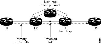
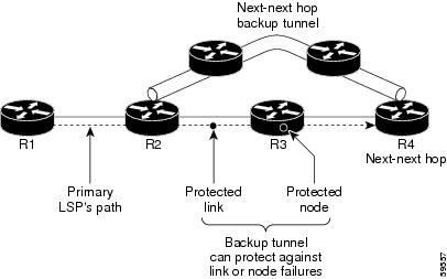

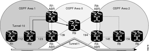
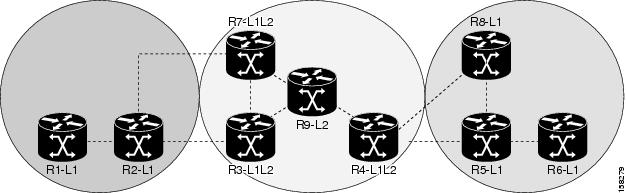
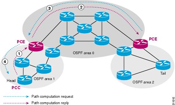
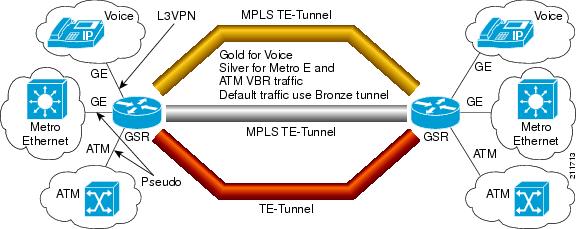
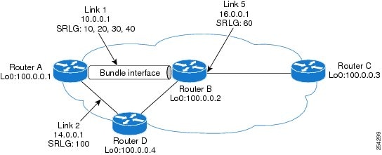
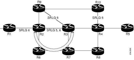
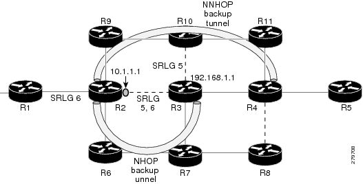
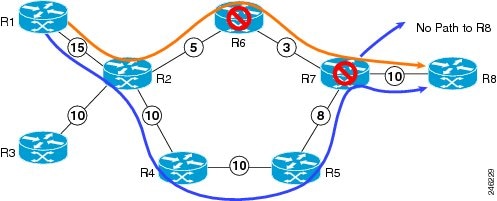
 Feedback
Contact Cisco
- Open a Support Case

- (Requires a Cisco Service Contract)
This Document Applies to These Products
- Collaboration Endpoints - Retired Products
- Conferencing - Retired Products
- Contact Center - Retired Products
- Optical Networking - Retired Products
- Routers - Retired Products
- Security - Retired Products
- Servers - Unified Computing (UCS) Retired Products
- Storage Networking Retired Products
- Switches - Retired Products
- Video - Retired Products
- Wireless - Retired Products