Implementing Cisco Express Forwarding
Available Languages
Contents
- Implementing Cisco Express Forwarding
- Prerequisites for Implementing Cisco Express Forwarding
- Information About Implementing Cisco Express Forwarding Software
- Key Features Supported in the Cisco Express Forwarding Implementation
- Benefits of CEF
- CEF Components
- Border Gateway Protocol Policy Accounting
- Reverse Path Forwarding (Strict and Loose)
- Per-Flow Load Balancing
- BGP Attributes Download
- How to Implement CEF
- Verifying CEF
- Configuring BGP Policy Accounting
- Verifying BGP Policy Accounting
- Configuring a Route Purge Delay
- Configuring Unicast RPF Checking
- Configuring Modular Services Card-to-Route Processor Management Ethernet Interface Switching
- Configuring Per-Flow Load Balancing
- Configuring a 7-Tuple Hash Algorithm
- Verifying the CEF Exact Route with 7-Tuple Parameters
- Configuring BGP Attributes Download
- Configuring BGP Attributes Download
- Configuration Examples for Implementing CEF on Routers Software
- Configuring BGP Policy Accounting: Example
- Verifying BGP Policy Statistics: Example
- Configuring Unicast RPF Checking: Example
- Configuring the Switching of Modular Services Card to Management Ethernet Interfaces on the Route Processor: Example
- Configuring Per-Flow Load Balancing: Example
- Configuring BGP Attributes Download: Example
- Additional References
Implementing Cisco Express Forwarding
Cisco Express Forwarding (CEF) is advanced, Layer 3 IP switching technology. CEF optimizes network performance and scalability for networks with large and dynamic traffic patterns, such as the Internet, on networks characterized by intensive web-based applications, or interactive sessions.
Note
For complete descriptions of the CEF commands listed in this module, you can refer to the Related Documents section of this module. To locate documentation for other commands that might appear in the course of executing a configuration task, search online in the master command index.
Feature History for Implementing CEF
Release
Modification
Release 3.2
This feature was introduced.
Release 3.3.0
Loose and Strict support for uRPF was added.
The CEF Nonrecursive Accounting feature was removed.
Release 3.5.0
IPv4 Strict uRPF support was added.
Release 3.7.0
The show cef bgp-attribute command was added.
Release 4.1.0
The N-Tuple Hashing feature was added.
- Prerequisites for Implementing Cisco Express Forwarding
- Information About Implementing Cisco Express Forwarding Software
- How to Implement CEF
- Configuration Examples for Implementing CEF on Routers Software
- Additional References
Prerequisites for Implementing Cisco Express Forwarding
The following prerequisites are required to implement Cisco Express Forwarding:
Information About Implementing Cisco Express Forwarding Software
To implement Cisco Express Forwarding features in this document you must understand the following concepts:
- Key Features Supported in the Cisco Express Forwarding Implementation
- Benefits of CEF
- CEF Components
- Border Gateway Protocol Policy Accounting
- Reverse Path Forwarding (Strict and Loose)
- Per-Flow Load Balancing
- BGP Attributes Download
Key Features Supported in the Cisco Express Forwarding Implementation
The following features are supported for CEF on Cisco IOS XR software:
Benefits of CEF
CEF offers the following benefits:
Improved performance—CEF is less CPU-intensive than fast-switching route caching. More CPU processing power can be dedicated to Layer 3 services such as quality of service (QoS) and encryption.
Scalability—CEF offers full switching capacity at each modular services card (MSC).
Resilience—CEF offers an unprecedented level of switching consistency and stability in large dynamic networks. In dynamic networks, fast-switched cache entries are frequently invalidated due to routing changes. These changes can cause traffic to be process switched using the routing table, rather than fast switched using the route cache. Because the Forwarding Information Base (FIB) lookup table contains all known routes that exist in the routing table, it eliminates route cache maintenance and the fast-switch or process-switch forwarding scenario. CEF can switch traffic more efficiently than typical demand caching schemes.
CEF Components
Cisco IOS XR softwareCEF always operates in CEF mode with two distinct components: a Forwarding Information Base (FIB) database and adjacency table—a protocol-independent adjacency information base (AIB).
CEF is a primary IP packet-forwarding database for Cisco IOS XR software. CEF is responsible for the following functions:
Software switching path
Maintaining forwarding table and adjacency tables (which are maintained by the AIB) for software and hardware forwarding engines
The following CEF forwarding tables are maintained in Cisco IOS XR software:
The protocol-dependent FIB process maintains the forwarding tables for IPv4 and IPv6 unicast in the route processor ( RP) and each MSC.
The FIB on each node processes Routing Information Base (RIB) updates, performing route resolution and maintaining FIB tables independently in the RP and each MSC. FIB tables on each node can be slightly different. Adjacency FIB entries are maintained only on a local node, and adjacency entries linked to FIB entries could be different.
Border Gateway Protocol Policy Accounting
Border Gateway Protocol (BGP) policy accounting measures and classifies IP traffic that is sent to, or received from, different peers. Policy accounting is enabled on an individual input or output interface basis, and counters based on parameters such as community list, autonomous system number, or autonomous system path are assigned to identify the IP traffic.
Note
There are two types of route policies. The first type (regular BGP route policies) is used to filter the BGP routes advertised into or out from the BGP links. This type of route policy is applied to the specific BGP neighbor. The second type (specific route policy) is used to set up a traffic index for the BGP prefixes. This route policy is applied to the global BGP IPv4 address family to set up the traffic index when the BGP routes are inserted into the RIB table. BGP policy accounting uses the second type of route policy.
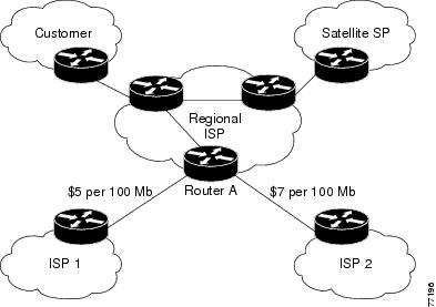
Using BGP policy accounting, you can account for traffic according to the route it traverses. Service providers can identify and account for all traffic by customer and bill accordingly. In Figure 1, BGP policy accounting can be implemented in Router A to measure packet and byte volumes in autonomous system buckets. Customers are billed appropriately for traffic that is routed from a domestic, international, or satellite source.
Note
BGP policy accounting measures and classifies IP traffic for BGP prefixes only.
Based on the specified routing policy, BGP policy accounting assigns each prefix a traffic index (bucket) associated with an interface. BGP prefixes are downloaded from the Routing Information Base (RIB) to the FIB along with the traffic index.
There are a total of 63 (1 to 63) traffic indexes (bucket numbers) that can be assigned for BGP prefixes. Internally, there is an accounting table associated with the traffic indexes to be created for each input (ingress) and output (egress) interface. The traffic indexes allow you to account for the IP traffic, where the source IP address, the destination IP address, or both are BGP prefixes.
Note
Traffic index 0 contains the packet count using Interior Gateway Protocol (IGP) routes.
Reverse Path Forwarding (Strict and Loose)
Unicast IPv4 and IPv6 Reverse Path Forwarding (uRPF), both strict and loose modes, help mitigate problems caused by the introduction of malformed or spoofed IP source addresses into a network by discarding IP packets that lack a verifiable IP source address. Unicast RPF does this by doing a reverse lookup in the CEF table. Therefore, Unicast Reverse Path Forwarding is possible only if CEF is enabled on the router.
Cisco IOS XR softwaresupports both modes of Unicast IPv4 Reverse Path Forwarding on all IP Services Engine (ISE/Engine 3) and Engine 5 line cards in the and the strict mode of Unicast IPv6 Reverse Path Forwarding on Engine 5 line cards.
Note
Unicast RPF allows packets with 0.0.0.0 source addresses and 255.255.255.255 destination addresses to pass so that Bootstrap Protocol and Dynamic Host Configuration Protocol (DHCP) will function properly.
When strict uRPF is enabled, the source address of the packet is checked in the FIB. If the packet is received on the same interface that would be used to forward the traffic to the source of the packet, the packet passes the check and is further processed; otherwise, it is dropped. Strict uRPF should only be applied where there is natural or configured symmetry. Because internal interfaces are likely to have routing asymmetry, that is, multiple routes to the source of a packet, strict uRPF should not be implemented on interfaces that are internal to the network.
Note
The behavior of strict RPF varies slightly by platform, number of recursion levels, and number of paths in Equal-Cost Multipath (ECMP) scenarios. A platform may switch to loose RPF check for some or all prefixes, even though strict RPF is configured.
When loose uRPF is enabled, the source address of the packet is checked in the FIB. If it exists and matches a valid forwarding entry, the packet passes the check and is further processed; otherwise, it is dropped.
Loose and strict uRPF supports two options: allow self-ping and allow default. The self-ping option allows the source of the packet to ping itself. The allow default option allows the lookup result to match a default routing entry. When the allow default option is enabled with the strict mode of the uRPF, the packet is processed further only if it arrived through the default interface.
Note
On s, strict uRPF supports load-balanced prefixes for a maximum of eight interfaces on the same line card. When a packet is received on a load-balanced prefix, it is verified against each of the interfaces in the load balance. If a packet is received on a load-balanced prefix with more than eight interfaces on the same line card, a loose uRPF check is performed, even if the packet is received on an interface that was configured for strict uRPF.
Per-Flow Load Balancing
Load balancing describes the functionality in a router that distributes packets across multiple links based on Layer 3 (network layer) and Layer 4 (transport layer) routing information. If the router discovers multiple paths to a destination, the routing table is updated with multiple entries for that destination.
Per-flow load balancing performs the following functions:
Incoming data traffic is evenly distributed over multiple equal-cost connections.
Incoming data Data traffic is evenly distributed over multiple equal-cost connections member links within a bundle interface.
Per-flow load balancing is the only load balancing algorithm that is used to perform Layer 2 bundle and Layer 3 (network layer) load balancing decisions on IPv4, IPv6, which are supported for the 7-tuple hash algorithm.
A 7-tuple hash algorithm provides more granular load balancing than the existing 3-tuple hash algorithm.
The same hash algorithm (3-tuple or 7-tuple) is used for load balancing over multiple equal-cost Layer 3 (network layer) paths. The Layer 3 (network layer) path is on a physical interface or on a bundle interface. In addition, load balancing over member links can occur within a Layer 2 bundle interface.
The cef load-balancing fields command allows you to select either the 3-tuple hash algorithm (default) or the 7-tuple hash algorithm.
The 3-tuple load-balance hash calculation contains the following Layer 3 (Network Layer) inputs:
Layer 3 (Network Layer) Routing Information
The 7-tuple load-balance hash calculation contains the 3-tuple inputs and the following additional following Layer 4 (Transport Layer) inputs:
BGP Attributes Download
The BGP Attributes Download feature enables you to display the installed BGP attributes in CEF. Configure the show cef bgp-attribute command to display the installed BGP attributes in CEF. You can use the show cef bgp-attribute attribute-id command and the show cef bgp-attribute local-attribute-id command to look at specific BGP attributes by attribute ID and local attribute ID.
How to Implement CEF
This section contains instructions for the following tasks:
- Verifying CEF
- Configuring BGP Policy Accounting
- Verifying BGP Policy Accounting
- Configuring a Route Purge Delay
- Configuring Unicast RPF Checking
- Configuring Modular Services Card-to-Route Processor Management Ethernet Interface Switching
- Configuring Per-Flow Load Balancing
- Configuring BGP Attributes Download
Verifying CEF
SUMMARY STEPS2. show cef {ipv4 | ipv6} summary
3. show cef {ipv4 | ipv6} detail
DETAILED STEPS
Command or Action Purpose Step 1 show cef {ipv4 | ipv6}
Example:RP/0/0/CPU0:router# show cef ipv4Displays the IPv4 or IPv6 CEF table. The next hop and forwarding interface are displayed for each prefix.
Note The output of the show cef command varies by location.
Step 2 show cef {ipv4 | ipv6} summary
Example:RP/0/0/CPU0:router# show cef ipv4 summaryDisplays a summary of the IPv4 or IPv6 CEF table.
Step 3 show cef {ipv4 | ipv6} detail
Example:RP/0/0/CPU0:router# show cef ipv4 detailDisplays detailed IPv4 or IPv6 CEF table information.
Step 4 show adjacency detail
Example:RP/0/0/CPU0:router# show adjacency detailDisplays detailed adjacency information, including Layer 2 information for each interface.
Note The output of the show adjacency command varies by location.
Configuring BGP Policy Accounting
This task allows you to configure BGP policy accounting.
Note
There are two types of route policies. BGP policy accounting uses the type that is used to set up a traffic index for the BGP prefixes. The route policy is applied to the global BGP IPv4 address family to set up the traffic index when the BGP routes are inserted into the RIB table.
BGP policy accounting enables per interface accounting for ingress and egress IP traffic based on the traffic index assigned to the source IP address (BGP prefix) and destination IP address (BGP prefix). The traffic index of BGP prefixes can be assigned according to the following parameters using Routing Policy Language (RPL):
Note
BGP policy accounting is supported on IPv4 prefixes only.
Two configuration tasks provide the ability to classify BGP prefixes that are in the RIB according to the prefix-set, AS-path-set, or the community-set parameters:
Use the route-policy command to define the policy for traffic index setup based on the prefix-set, AS-path-set, or community-set.
Use the BGP table-policy command to apply the defined route policy to the global BGP IPv4 unicast address family.
See the Cisco IOS XR Routing Command Reference for the Cisco XR 12000 Series Router for information on the route-policy and table-policy commands.
BGP policy accounting can be enabled on each interface with the following options:
Verifying BGP Policy Accounting
This task allows you to verify BGP policy accounting.
Note
BGP policy accounting is supported on IPv4 prefixes.
Before You BeginSUMMARY STEPSBGP policy accounting must be configured. See the Configuring BGP Policy Accounting.
6. show cef ipv4 prefix detail
7. show cef ipv4 interface type interface-path-id bgp-policy-statistics
DETAILED STEPS
Command or Action Purpose Step 1 show route bgp
Example:RP/0/0/CPU0:router# show route bgpDisplays all BGP routes with traffic indexes.
Step 2 show bgp summary
Example:RP/0/0/CPU0:router# show bgp summaryDisplays the status of all BGP neighbors.
Step 3 show bgp ip-address
Example:RP/0/0/CPU0:router# show bgp 40.1.1.1Displays BGP prefixes with BGP attributes.
Step 4 show route ipv4 ip-address
Example:RP/0/0/CPU0:router# show route ipv4 40.1.1.1Displays the specific BGP route with the traffic index in the RIB.
Step 5 show cef ipv4 prefix
Example:RP/0/0/CPU0:router# show cef ipv4 40.1.1.1Displays the specific BGP prefix with the traffic index in the RP FIB.
Step 6 show cef ipv4 prefix detail
Example:RP/0/0/CPU0:router# show cef ipv4 40.1.1.1 detailDisplays the specific BGP prefix with detailed information in the RP FIB.
Step 7 show cef ipv4 interface type interface-path-id bgp-policy-statistics
Example:RP/0/0/CPU0:router# show cef ipv4 interface TenGigE 0/2/0/4 bgp-policy-statisticsDisplays the BGP Policy Accounting statistics for the specific interface.
Configuring a Route Purge Delay
SUMMARY STEPSThis task allows you to configure a route purge delay. A purge delay purges routes when the RIB or other related process experiences a failure.
3. Use one of the following commands:
DETAILED STEPSConfiguring Unicast RPF Checking
SUMMARY STEPSThis task allows you to configure unicast Reverse Path Forwarding (uRPF) RPF checking. Unicast RPF checking allows you to mitigate problems caused by malformed or forged (spoofed) IP source addresses that pass through a router. Malformed or forged source addresses can indicate denial-of-service (DoS) attacks based on source IP address spoofing.
2. interface type interface-path-id
3. {ipv4 | ipv6} verify unicast source reachable-via {any | rx} [allow-default] [allow-self-ping]
DETAILED STEPSConfiguring Modular Services Card-to-Route Processor Management Ethernet Interface Switching
SUMMARY STEPS3. Use one of the following commands:
DETAILED STEPSConfiguring Per-Flow Load Balancing
This section describes the following tasks to configure per-flow load balancing:
Configuring a 7-Tuple Hash Algorithm
SUMMARY STEPS2. cef load-balancing fields {L3 | L4}
4. show cef {ipv4 | ipv6} summary [location node-id]
DETAILED STEPS
Command or Action Purpose Step 1 configure
Example:RP/0/0/CPU0:router# configureEnters global configuration mode.
Step 2 cef load-balancing fields {L3 | L4}
Example:RP/0/0/CPU0:router(config)# cef load-balancing fields L4Configures the hashing algorithm that is used for load balancing during forwarding. The example shows that the L4 field is selected.
Use the L3 keyword to specify the Layer 3 load-balancing for the hash algorithm
Since L3 is configured as the default value, you do not need to use the cef load-balancing fields command unless you want to configure Layer 4.
Use the L4 keyword to specify the Layer 3 and Layer 4 load-balancing for the hash algorithm.
For a list of the inputs for Layer 3 and Layer 4, see Per-Flow Load Balancing.
Step 3 Do one of the following:
Example:RP/0/0/CPU0:router(config)# endor
RP/0/0/CPU0:router(config)# commitSaves configuration changes.
When you issue the end command, the system prompts you to commit changes:
Uncommitted changes found, commit them before exiting(yes/no/cancel)?[cancel]:
Entering yes saves configuration changes to the running configuration file, exits the configuration session, and returns the router to EXEC mode.
Entering no exits the configuration session and returns the router to EXEC mode without committing the configuration changes.
Entering cancel leaves the router in the current configuration session without exiting or committing the configuration changes.
Use the commit command to save the configuration changes to the running configuration file and remain within the configuration session.
Step 4 show cef {ipv4 | ipv6} summary [location node-id]
Example:RP/0/0/CPU0:router# show cef ipv4 summaryDisplays the load balancing field for the IPv4 or IPv6 CEF table.
Verifying the CEF Exact Route with 7-Tuple Parameters
SUMMARY STEPSThe following 7-tuple parameters are specified to obtain the CEF exact route for both IPv4 and IPv6:
Source address
Destination address
Source port and range of destination ports
Protocol
Ingress interface
Router ID
To display the path an MPLS flow would take, use the show mpls forwarding exact-route command. The MPLS flow comprises a source address and a destination address.
To display the path a bundle flow would take, use the bundle-hash command. The bundle flow comprises a source and a destination address. For more information, see Cisco IOS XR Interface and Hardware Component Command Reference for the Cisco XR 12000 Series Router .
To verify the IPv4 7-tuple parameters, perform the following steps:
1. Configure parallel interfaces between back-to-back routers.
2. Create route traffic streams so that there is a stream placed onto each configured interface.
3. Use the show cef ipv4 exact-route command in EXEC mode to verify that the interface selected for load balancing matches with the output from this command. The following example shows the exact route for the Layer 4 information:
4. Configure Equal Cost Multipath Protocol (ECMP) interfaces, for example, between back-to-back routers.
5. Create route traffic streams so that there is a stream placed onto each configured interface.
6. Use the show cef ipv6 exact-route command in EXEC mode to verify that the interface selected for load balancing matches with the output from this command. The following example shows the exact route for the Layer 4 information:
DETAILED STEPS
Configuring BGP Attributes Download
This task allows you to configure the BGP Attributes Download feature.
Configuring BGP Attributes Download
SUMMARY STEPS2. cef bgp attribute {attribute-id | local-attribute-id }
3. Use one of the following commands:
DETAILED STEPSConfiguration Examples for Implementing CEF on Routers Software
This section provides the following configuration examples:
- Configuring BGP Policy Accounting: Example
- Verifying BGP Policy Statistics: Example
- Configuring Unicast RPF Checking: Example
- Configuring the Switching of Modular Services Card to Management Ethernet Interfaces on the Route Processor: Example
- Configuring Per-Flow Load Balancing: Example
- Configuring BGP Attributes Download: Example
Configuring BGP Policy Accounting: Example
The following example shows how to configure BGP policy accounting.
Configure loopback interfaces for BGP router-id:
interface Loopback1
ipv4 address
190.1.1.1 255.255.255.255
Configure interfaces with the BGP policy accounting options:
interface TenGigE0/2/0/2
 mtu 1514
 ipv4 address
17.1.0.1 255.255.255.0
 proxy-arp
 ipv4 directed-broadcast
 ipv4 bgp policy accounting input source-accounting destination-accounting
 ipv4 bgp policy accounting output source-accounting destination-accounting
!
interface TenGigE0/2/0/2.1
 ipv4 address
17.1.1.1 255.255.255.0
 ipv4 bgp policy accounting input source-accounting destination-accounting
 ipv4 bgp policy accounting output source-accounting destination-accounting
 dot1q vlan 1
!
interface TenGigE0/2/0/4
 mtu 1514
 ipv4 address
18.1.0.1 255.255.255.0
 proxy-arp
 ipv4 directed-broadcast
 ipv4 bgp policy accounting input source-accounting destination-accounting
 ipv4 bgp policy accounting output source-accounting destination-accounting
!
interface TenGigE0/2/0/4.1
 ipv4 address
18.1.
1.1 255.255.255.0
 ipv4 bgp policy accounting input source-accounting destination-accounting
 ipv4 bgp policy accounting output source-accounting destination-accounting
 dot1q vlan 1
!
interface gigabitethernet 0/0/0/4
 mtu 4474
 ipv4 address
4.1.0.
1 255.255.0.0
 ipv4 directed-broadcast
 ipv4 bgp policy accounting input source-accounting destination-accounting
 ipv4 bgp policy accounting output source-accounting destination-accounting
 encapsulation ppp
 gigabitethernet
  crc 32
 !
 keepalive disable
!
interface gigabitethernet0/0/0/8
 mtu 4474
 ipv4 address
8.
1.0.1 255.255.0.0
 ipv4 directed-broadcast
 ipv4 bgp policy accounting input source-accounting destination-accounting
 ipv4 bgp policy accounting output source-accounting destination-accounting
 gigabitethernet
  crc 32
 !
 keepalive disable
!
Configure controller:
controller gigabitethernet0/0/0/4
 ais-shut
 path
  ais-shut
 !
 threshold sf-ber 5
!
controller SONET0/0/0/8
 ais-shut
 path
  ais-shut
 !
 threshold sf-ber 5
!
Configure AS-path-set and prefix-set:
as-path-set as107
  ios-regex '107$'
end-set

as-path-set as108
  ios-regex '108$'
end-set

prefix-set RT-65.0
  65.0.0.0/16 ge 16 le 32
end-set

prefix-set RT-66.0
  66.0.0.0/16 ge 16 le 32
end-set
Configure the route-policy (table-policy) to set up the traffic indexes based on each prefix, AS-path-set, and prefix-set:
route-policy bpa1

  if destination in  (
27.1.1.0/24) then
    set traffic-index 1
  elseif destination in  (
27.1.2.0/24) then
    set traffic-index 2
  elseif destination in  (
27.1.3.0/24) then
    set traffic-index 3
  elseif destination in  (
27.1.4.0/24) then
    set traffic-index 4
  elseif destination in  (
27.1.5.0/24) then
    set traffic-index 5
  endif

  if destination in  (
28.1.1.0/24) then
    set traffic-index 6
  elseif destination in  (
28.1.2.0/24) then
    set traffic-index 7
  elseif destination in  (
28.1.3.0/24) then
    set traffic-index 8
  elseif destination in  (
28.1.4.0/24) then
    set traffic-index 9
  elseif destination in  (
28.1.5.0/24) then
    set traffic-index 10
  endif

  if as-path in as107 then
       set traffic-index 7
  elseif as-path in as108 then
       set traffic-index 8
  endif

  if destination in RT-65.0 then
     set traffic-index 15
  elseif destination in RT-66.0 then
     set traffic-index 16
  endif

end-policy
Configure the regular BGP route-policy to pass or drop all the BGP routes:
route-policy drop-all
  drop
end-policy
!
route-policy pass-all
  pass
end-policy
!
Configure the BGP router and apply the table-policy to the global ipv4 address family:
router bgp 100
 bgp router-id Loopback1
 bgp graceful-restart
 bgp as-path-loopcheck
 address-family ipv4 unicast
  table-policy bpa1
  maximum-paths 8
  bgp dampening
 !
Configure the BGP neighbor-group:
neighbor-group ebgp-peer-using-int-addr
  address-family ipv4 unicast
   policy pass-all in
   policy drop-all out
  !
 !
 neighbor-group ebgp-peer-using-int-addr-121
  remote-as 121
  address-family ipv4 unicast
   policy pass-all in
   policy drop-all out
  !
 !
 neighbor-group ebgp-peer-using-int-addr-pass-out
  address-family ipv4 unicast
   policy pass-all in
   policy pass-all out
  !
 !
Configure BGP neighbors:
neighbor
4.
1.0.2
  remote-as 107
  use neighbor-group ebgp-peer-using-int-addr
 !
 neighbor
8.
1.0.2
  remote-as 108
  use neighbor-group ebgp-peer-using-int-addr
 !
 neighbor
17.
1.0.2
  use neighbor-group ebgp-peer-using-int-addr-121
 !
 neighbor
17.1.
1.2
  use neighbor-group ebgp-peer-using-int-addr-121
 !
neighbor
18.
1.0.2
  remote-as 122
  use neighbor-group ebgp-peer-using-int-addr
 !
 neighbor
18.
1.1.2
  remote-as 1221
  use neighbor-group ebgp-peer-using-int-addr
 !
end
Verifying BGP Policy Statistics: Example
The following example shows how to verify the traffic index setup for each BGP prefix and BGP Policy Accounting statistics on ingress and egress interfaces. The following traffic stream is configured for this example:
Traffic comes in from TenGigE0/2/0/4 and goes out to 5 VLAN subinterfaces under TenGigE0/2/0/2
Traffic comes in from GigabitEthernet 0/0/08 and goes out to GigabitEthernet 0/0/0/4
show cef ipv4 interface gigabitethernet 0/0/0/8 bgp-policy-statistics

gigabitethernet0/0/0/8 is up
Input BGP policy accounting on dst IP address enabled
  buckets      packets       bytes
  7            5001160   500116000
  15          10002320  1000232000
Input BGP policy accounting on src IP address enabled
  buckets      packets       bytes
  8            5001160   500116000
  16          10002320  1000232000
Output BGP policy accounting on dst IP address enabled
  buckets      packets       bytes
  0                 15         790
Output BGP policy accounting on src IP address enabled
  buckets      packets       bytes
  0                 15         790

show cef ipv4 interface gigabitethernet 0/0/0/4 bgp-policy-statistics

gigabitethernet0/0/0/4 is up
Input BGP policy accounting on dst IP address enabled
  buckets      packets       bytes
Input BGP policy accounting on src IP address enabled
  buckets      packets       bytes
Output BGP policy accounting on dst IP address enabled
  buckets      packets       bytes
  0                 13         653
  7            5001160   500116000
  15          10002320  1000232000
Output BGP policy accounting on src IP address enabled
  buckets      packets       bytes
  0                 13         653
  8            5001160   500116000
  16          10002320  1000232000

show cef ipv4 interface TenGigE0/2/0/4 bgp-policy-statistics

TenGigE0/2/0/4 is up
Input BGP policy accounting on dst IP address enabled
  buckets      packets       bytes
  1            3297102   329710200
  2            3297102   329710200
  3            3297102   329710200
  4            3297101   329710100
  5            3297101   329710100
Input BGP policy accounting on src IP address enabled
  buckets      packets       bytes
  6            3297102   329710200
  7            3297102   329710200
  8            3297102   329710200
  9            3297101   329710100
  10           3297101   329710100
Output BGP policy accounting on dst IP address enabled
  buckets      packets       bytes
  0                 15         733
Output BGP policy accounting on src IP address enabled
  buckets      packets       bytes
  0                 15         733

show cef ipv4 interface TenGigE0/2/0/2.1 bgp-policy-statistics

TenGigE0/2/0/2.1 is up
Input BGP policy accounting on dst IP address enabled
  buckets      packets       bytes
Input BGP policy accounting on src IP address enabled
  buckets      packets       bytes
Output BGP policy accounting on dst IP address enabled
  buckets      packets       bytes
  0                 15         752
  1            3297102   329710200
  2            3297102   329710200
  3            3297102   329710200
  4            3297101   329710100
  5            3297101   329710100
Output BGP policy accounting on src IP address enabled
  buckets      packets       bytes
  0                 15         752
  6            3297102   329710200
  7            3297102   329710200
  8            3297102   329710200
  9            3297101   329710100
  10           3297101   329710100
The following example show how to verify BGP routes and traffic indexes:
show route bgp

B
   27.1.1.0/24 [20/0] via
17.
1.1.2, 00:07:09
      Traffic Index 1

B    27.1.2.0/24 [20/0] via
17.
1.1.2, 00:07:09
      Traffic Index 2
B
27.1.3.0/24 [20/0] via
17.
1.1.2, 00:07:09
      Traffic Index 3
B
27.1.4.0/24 [20/0] via
17.
1.1.2, 00:07:09
      Traffic Index 4
B
27.1.5.0/24 [20/0] via
17.
1.1.2, 00:07:09
      Traffic Index 5
B
28.
1.1.0/24 [20/0] via
18.
1.1.2, 00:07:09
      Traffic Index 6
B
28.
1.2.0/24 [20/0] via
18.
1.1.2, 00:07:09
      Traffic Index 7
B
28.
1.3.0/24 [20/0] via
18.
1.1.2, 00:07:09
      Traffic Index 8
B
28.
1.4.0/24 [20/0] via
18.
1.1.2, 00:07:09
      Traffic Index 9
B
28.
1.5.0/24 [20/0] via
18.
1.1.2, 00:07:09
      Traffic Index 10
B
65.
0.1.0/24 [20/0] via
4.
1.0.2, 00:07:09
      Traffic Index 15
B
65.
0.2.0/24 [20/0] via
4.
1.0.2, 00:07:09
      Traffic Index 15
B
65.
0.3.0/24 [20/0] via
4.
1.0.2, 00:07:09
      Traffic Index 15
B
65.
0.
4.0/24 [20/0] via
4.
1.0.2, 00:07:09
      Traffic Index 15
B
65.
0.5.0/24 [20/0] via
4.
1.0.2, 00:07:09
      Traffic Index 15
B
65.
0.6.0/24 [20/0] via
4.
1.0.2, 00:07:09
      Traffic Index 15
B
65.
0.7.0/24 [20/0] via
4.
1.0.2, 00:07:09
      Traffic Index 15
B
65.
0.8.0/24 [20/0] via
4.
1.0.2, 00:07:09
      Traffic Index 15
B
65.
0.9.0/24 [20/0] via
4.
1.0.2, 00:07:09
      Traffic Index 15
B
65.
0.10.0/24 [20/0] via
4.
1.0.2, 00:07:09
      Traffic Index 15
B
66.
0.1.0/24 [20/0] via
8.
1.0.2, 00:07:09
      Traffic Index 16
B
66.
0.2.0/24 [20/0] via
8.
1.0.2, 00:07:09
      Traffic Index 16
B
66.
0.3.0/24 [20/0] via
8.
1.0.2, 00:07:09
      Traffic Index 16
B
66.
0.4.0/24 [20/0] via
8.
1.0.2, 00:07:09
      Traffic Index 16
B
66.
0.5.0/24 [20/0] via
8.
1.0.2, 00:07:09
      Traffic Index 16
B
66.
0.6.0/24 [20/0] via
8.
1.0.2, 00:07:09
      Traffic Index 16
B
66.
0.7.0/24 [20/0] via
8.
1.0.2, 00:07:09
      Traffic Index 16
B
66.
0.8.0/24 [20/0] via
8.
1.0.2, 00:07:09
      Traffic Index 16
B
66.
0.9.0/24 [20/0] via
8.
1.0.2, 00:07:09
      Traffic Index 16
B
66.
0.10.0/24 [20/0] via
8.
1.0.2, 00:07:09
      Traffic Index 16
B
67.
0.1.0/24 [20/0] via
4.
1.0.2, 00:07:09
      Traffic Index 7
B
67.
0.2.0/24 [20/0] via
4.
1.0.2, 00:07:09
      Traffic Index 7
B
67.
0.3.0/24 [20/0] via
4.
1.0.2, 00:07:09
      Traffic Index 7
B
67.
0.4.0/24 [20/0] via
4.
1.0.2, 00:07:09
      Traffic Index 7
B
67.
0.5.0/24 [20/0] via
4.
1.0.2, 00:07:09
      Traffic Index 7
B
   67.
0.6.0/24 [20/0] via
4.
1.0.2, 00:07:09
      Traffic Index 7
B
   67.
0.7.0/24 [20/0] via
4.
1.0.2, 00:07:09
      Traffic Index 7
B
   67.
0.8.0/24 [20/0] via
4.
1.0.2, 00:07:09
      Traffic Index 7
B
   67.
0.9.0/24 [20/0] via
4.
1.0.2, 00:07:09
      Traffic Index 7
B
   67.
0.10.0/24 [20/0] via
4.
1.0.2, 00:07:09
      Traffic Index 7
B
68.
0.1.0/24 [20/0] via
8.
1.0.2, 00:07:09
      Traffic Index 8
B
   68.
0.2.0/24 [20/0] via
8.
1.0.2, 00:07:09
      Traffic Index 8
B
   68.
0.3.0/24 [20/0] via
8.
1.0.2, 00:07:09
      Traffic Index 8
B
   68.
0.4.0/24 [20/0] via
8.
1.0.2, 00:07:09
      Traffic Index 8
B
   68.
0.5.0/24 [20/0] via
8.
1.0.2, 00:07:09
      Traffic Index 8
B
   68.
0.6.0/24 [20/0] via
8.
1.0.2, 00:07:09
      Traffic Index 8
B
   68.
0.7.0/24 [20/0] via
8.
1.0.2, 00:07:09
      Traffic Index 8
B
   68.
0.8.0/24 [20/0] via
8.
1.0.2, 00:07:09
      Traffic Index 8
B
   68.
0.9.0/24 [20/0] via
8.
1.0.2, 00:07:09
      Traffic Index 8
B
   68.
0.10.0/24 [20/0] via
8.
1.0.2, 00:07:09
      Traffic Index 8

show bgp summary

BGP router identifier
190.
1.
1.
1, local AS number 100
BGP generic scan interval 60 secs
BGP main routing table version 151
Dampening enabled
BGP scan interval 60 secs
BGP is operating in STANDALONE mode.

Process         RecvTblVer    bRIB/RIB  SendTblVer
Speaker                151         151         151

Neighbor        Spk    AS MsgRcvd MsgSent   TblVer  InQ OutQ Up/Down  St/PfxRcd

4.
1.0.2           0   107      54      53      151    0    0 00:25:26       20

8.1.0.2           0   108      54      53      151    0    0 00:25:28       20

17.1.0.2          0   121      53      54      151    0    0 00:25:42        0

17.1.1.2          0   121      53      53      151    0    0 00:25:06        5

17.1.2.2          0   121      52      54      151    0    0 00:25:04        0

17.1.3.2          0   121      52      53      151    0    0 00:25:26        0

17.1.4.2          0   121      53      54      151    0    0 00:25:41        0

17.1.5.2          0   121      53      54      151    0    0 00:25:43        0

17.1.6.2          0   121      51      53      151    0    0 00:24:59        0

17.1.7.2          0   121      51      52      151    0    0 00:24:44        0

17.1.8.2          0   121      51      52      151    0    0 00:24:49        0

18.
1.0.2          0   122      52      54      151    0    0 00:25:21        0

18.
1.1.2          0  1221      54      54      151    0    0 00:25:43        5

18.
1.2.2          0  1222      53      54      151    0    0 00:25:38        0

18.
1.3.2          0  1223      52      53      151    0    0 00:25:17        0

18.
1.4.2          0  1224      51      52      151    0    0 00:24:57        0

18.
1.5.2          0  1225      52      53      151    0    0 00:25:14        0

18.
1.6.2          0  1226      52      54      151    0    0 00:25:04        0

18.
1.7.2          0  1227      52      54      151    0    0 00:25:13        0

18.
1.8.2          0  1228      53      54      151    0    0 00:25:36        0

show bgp 27.1.1.1

BGP routing table entry for 27.1.1.0/24
Versions:
  Process           bRIB/RIB  SendTblVer
  Speaker                102         102
Paths: (1 available, best #1)
  Not advertised to any peer
  Received by speaker 0
  121

17.1.1.2 from
17.1.1.2 (
17.1.1.2)
      Origin incomplete, localpref 100, valid, external, best
      Community: 27:1 121:1

show bgp
28.1.1.1

BGP routing table entry for
28.1.1.0/24
Versions:
  Process           bRIB/RIB  SendTblVer
  Speaker                107         107
Paths: (1 available, best #1)
  Not advertised to any peer
  Received by speaker 0
  1221

    18.
1.1.2 from
18.
1.1.2 (18.1.1.2)
      Origin incomplete, localpref 100, valid, external, best
      Community: 28:1 1221:1

show bgp
65.0.1.1

BGP routing table entry for
65.0.1.0/24
Versions:
  Process           bRIB/RIB  SendTblVer
  Speaker                112         112
Paths: (1 available, best #1)
  Not advertised to any peer
  Received by speaker 0
  107

4.1.0.2 from
4.1.0.2 (
4.1.0.2)
      Origin incomplete, localpref 100, valid, external, best
      Community: 107:65

show bgp
66.
0.1.1

BGP routing table entry for
66.
0.1.0/24
Versions:
  Process           bRIB/RIB  SendTblVer
  Speaker                122         122
Paths: (1 available, best #1)
  Not advertised to any peer
  Received by speaker 0
  108
    8.1.0.2 from 8.1.0.2 (8.1.0.2)
      Origin incomplete, localpref 100, valid, external, best
      Community: 108:66

show bgp 67.0.1.1

BGP routing table entry for 67.0.1.0/24
Versions:
  Process           bRIB/RIB  SendTblVer
  Speaker                132         132
Paths: (1 available, best #1)
  Not advertised to any peer
  Received by speaker 0
  107
    4.1.0.2 from 4.1.0.2 (4.1.0.2)
      Origin incomplete, localpref 100, valid, external, best
      Community: 107:67

show bgp 68.0.1.1

BGP routing table entry for 68.0.1.0/24
Versions:
  Process           bRIB/RIB  SendTblVer
  Speaker                142         142
Paths: (1 available, best #1)
  Not advertised to any peer
  Received by speaker 0
  108
    8.1.0.2 from 8.1.0.2 (8.1.0.2)
      Origin incomplete, localpref 100, valid, external, best
      Community: 108:68

show route ipv4 27.1.1.1

Routing entry for 27.1.1.0/24
  Known via "bgp 100", distance 20, metric 0
  Tag 121, type external, Traffic Index 1
  Installed Nov 11 21:14:05.462
  Routing Descriptor Blocks
    17.1.1.2, from 17.1.1.2
      Route metric is 0
  No advertising protos.

show route ipv4 28.1.1.1

Routing entry for 28.1.1.0/24
  Known via "bgp 100", distance 20, metric 0
  Tag 1221, type external, Traffic Index 6
  Installed Nov 11 21:14:05.462
  Routing Descriptor Blocks
    18.1.1.2, from 18.1.1.2
      Route metric is 0
  No advertising protos.

show route ipv4 65.0.1.1

Routing entry for 65.0.1.0/24
  Known via "bgp 100", distance 20, metric 0
  Tag 107, type external, Traffic Index 15
  Installed Nov 11 21:14:05.462
  Routing Descriptor Blocks
    4.1.0.2, from 4.1.0.2
      Route metric is 0
  No advertising protos.

show route ipv4 66.0.1.1

Routing entry for 66.0.1.0/24
  Known via "bgp 100", distance 20, metric 0
  Tag 108, type external, Traffic Index 16
  Installed Nov 11 21:14:05.462
  Routing Descriptor Blocks
    8.1.0.2, from 8.1.0.2
      Route metric is 0
  No advertising protos.

show route ipv4 67.0.1.1

Routing entry for 67.0.1.0/24
  Known via "bgp 100", distance 20, metric 0
  Tag 107, type external, Traffic Index 7
  Installed Nov 11 21:14:05.462
  Routing Descriptor Blocks
    4.1.0.2, from 4.1.0.2
      Route metric is 0
  No advertising protos.

show route ipv4 68.0.1.1

Routing entry for 68.0.1.0/24
  Known via "bgp 100", distance 20, metric 0
  Tag 108, type external, Traffic Index 8
  Installed Nov 11 21:14:05.462
  Routing Descriptor Blocks
    8.1.0.2, from 8.1.0.2
      Route metric is 0
  No advertising protos.

show cef ipv4 27.1.1.1

27.1.1.0/24, version 263, source-destination sharing
Prefix Len 24, Traffic Index 1, precedence routine (0)
  via 17.1.1.2, 0 dependencies, recursive
    next hop 17.1.1.2/24, TenGigE0/2/0/2.1 via 17.1.1.0/24
    valid remote adjacency
  Recursive load sharing using 17.1.1.0/24

show cef ipv4 28.1.1.1

28.1.1.0/24, version 218, source-destination sharing
Prefix Len 24, Traffic Index 6, precedence routine (0)
  via 18.1.1.2, 0 dependencies, recursive
    next hop 18.1.1.2/24, TenGigE0/2/0/4.1 via 18.1.1.0/24
    valid remote adjacency
  Recursive load sharing using 18.1.1.0/24

show cef ipv4 65.0.1.1

65.0.1.0/24, version 253, source-destination sharing
Prefix Len 24, Traffic Index 15, precedence routine (0)
  via 4.1.0.2, 0 dependencies, recursive
    next hop 4.1.0.2/16, gigabitethernet0/0/0/4 via 4.1.0.0/16
    valid remote adjacency
  Recursive load sharing using 4.1.0.0/16

show cef ipv4 66.0.1.1

66.0.1.0/24, version 233, source-destination sharing
Prefix Len 24, Traffic Index 16, precedence routine (0)
  via 8.1.0.2, 0 dependencies, recursive
    next hop 8.1.0.2/16, gigabitethernet 0/0/0/8 via 8.1.0.0/16
    valid remote adjacency
  Recursive load sharing using 8.1.0.0/16

show cef ipv4 67.0.1.1

67.0.1.0/24, version 243, source-destination sharing
Prefix Len 24, Traffic Index 7, precedence routine (0)
  via 4.1.0.2, 0 dependencies, recursive
    next hop 4.1.0.2/16, gigabitethernet 0/0/0/4 via 4.1.0.0/16
    valid remote adjacency
  Recursive load sharing using 4.1.0.0/16

show cef ipv4 68.0.1.1

68.0.1.0/24, version 223, source-destination sharing
Prefix Len 24, Traffic Index 8, precedence routine (0)
  via 8.1.0.2, 0 dependencies, recursive
    next hop 8.1.0.2/16, gigabitethernet0/0/0/8 via 8.1.0.0/16
    valid remote adjacency
  Recursive load sharing using 8.1.0.0/16

show cef ipv4 27.1.1.1 detail

27.1.1.0/24, version 263, source-destination sharing
Prefix Len 24, Traffic Index 1, precedence routine (0)
  via 17.1.1.2, 0 dependencies, recursive
    next hop 17.1.1.2/24, TenGigE0/2/0/2.1 via 17.1.1.0/24
    valid remote adjacency

  Recursive load sharing using 17.1.1.0/24
  Load distribution: 0 (refcount 6)

  Hash  OK  Interface                 Address  Packets
  1     Y   TenGigE0/2/0/2.1          (remote)               0

show cef ipv4 28.1.1.1 detail

28.1.1.0/24, version 218, source-destination sharing
Prefix Len 24, Traffic Index 6, precedence routine (0)
  via 18.1.1.2, 0 dependencies, recursive
    next hop 18.1.1.2/24, TenGigE0/2/0/4.1 via 18.1.1.0/24
    valid remote adjacency

  Recursive load sharing using 18.1.1.0/24
  Load distribution: 0 (refcount 6)

  Hash  OK  Interface                 Address  Packets
  1     Y   TenGigE0/2/0/4.1          (remote)               0

show cef ipv4 65.0.1.1 detail

65.0.1.0/24, version 253, source-destination sharing
Prefix Len 24, Traffic Index 15, precedence routine (0)
  via 4.1.0.2, 0 dependencies, recursive
    next hop 4.1.0.2/16, gigabitethernet0/0/0/4 via 4.1.0.0/16
    valid remote adjacency

  Recursive load sharing using 4.1.0.0/16
  Load distribution: 0 (refcount 21)

  Hash  OK  Interface                 Address  Packets
  1     Y   gigabitethernet0/0/0/4                (remote)               0

show cef ipv4 66.0.1.1 detail

66.0.1.0/24, version 233, source-destination sharing
Prefix Len 24, Traffic Index 16, precedence routine (0)
  via 8.1.0.2, 0 dependencies, recursive
    next hop 8.1.0.2/16, gigabitethernet0/0/0/8 via 8.1.0.0/16
    valid remote adjacency

  Recursive load sharing using 8.1.0.0/16
  Load distribution: 0 (refcount 21)

  Hash  OK  Interface                 Address  Packets
  1     Y   gigabitethernet 0/0/0/8                (remote)               0

show cef ipv4 67.0.1.1 detail

67.0.1.0/24, version 243, source-destination sharing
Prefix Len 24, Traffic Index 7, precedence routine (0)
  via 4.1.0.2, 0 dependencies, recursive
    next hop 4.1.0.2/16, gigabitethernet 0/0/0/4 via 4.1.0.0/16
    valid remote adjacency

  Recursive load sharing using 4.1.0.0/16
  Load distribution: 0 (refcount 21)

  Hash  OK  Interface                 Address  Packets
  1     Y   gigabitethernet 0/0/0/4                (remote)               0

show cef ipv4 68.0.1.1 detail

68.0.1.0/24, version 223, source-destination sharing
Prefix Len 24, Traffic Index 8, precedence routine (0)
  via 8.1.0.2, 0 dependencies, recursive
    next hop 8.1.0.2/16, gigabitethernet 0/0/0/8 via 8.1.0.0/16
    valid remote adjacency

  Recursive load sharing using 8.1.0.0/16
  Load distribution: 0 (refcount 21)

  Hash  OK  Interface                 Address  Packets
  1     Y   gigabitethernet 0/0/0/8                (remote)               0
Configuring Unicast RPF Checking: Example
The following example shows how to configure unicast RPF checking:
configure
interface gigabitethernet 0/0/0/1
ipv4 verify unicast source reachable-via rx
end
Configuring the Switching of Modular Services Card to Management Ethernet Interfaces on the Route Processor: Example
The following example shows how to configure the switching of the MSC to Management Ethernet interfaces on the route processor:
configure
rp mgmtethernet forwarding
end
Configuring Per-Flow Load Balancing: Example
The following examples show how to configure Layer 3 and Layer 4 load-balancing for the hash algorithm from the cef load-balancing fields command, and how to verify summary information for the CEF table from the show cef summary command:
Configuring Layer 3 load-balancing
configure
 cef load-balancing fields L3
 end
 !
show cef summary
Router ID is 10.6.6.6

IP CEF with switching (Table Version 0) for node0_0_CPU0

  Load balancing: L3
  Tableid 0xe0000000 (0x9cbb51b0), Vrfid 0x60000000, Vrid 0x20000000, Flags 0x2031
  Vrfname default, Refcount 577
  300 routes, 0 protected, 0 reresolve, 0 unresolved (0 old, 0 new), 21600 bytes
  212 load sharing elements, 62576 bytes, 324 references
  19 shared load sharing elements, 5388 bytes
  193 exclusive load sharing elements, 57188 bytes
  622 local route bufs received, 1 remote route bufs received,  0 mix bufs received
  176 local routes, 0 remote routes
  4096 total local route updates processed
  0 total remote route updates processed
  0 pkts pre-routed to cust card
  0 pkts received from core card
  0 CEF route update drops, 96 revisions of existing leaves
  0 CEF route update drops due to version mis-match
  Resolution Timer: 15s
  0 prefixes modified in place
  0 deleted stale prefixes
  82 prefixes with label imposition, 107 prefixes with label information
 95 next hops
  0 incomplete next hops

0 PD backwalks on LDIs with backup path
Configuring Layer 4 load-balancing
configure cef load-balancing fields L4 end ! show cef summary Router ID is 10 1.1.1.101 IP CEF with switching (Table Version 0) for node0_RP0_CPU0 Load balancing: L4 Tableid 0xe0000000, Vrfid 0x60000000, Vrid 0x20000000, Flags 0x301 Vrfname default, Refcount 286242 286122 routes, 0 reresolve, 0 unresolved (0 old, 0 new), 20600784 bytes 11124 load sharing elements, 3014696 bytes, 297064 references 8 shared load sharing elements, 3008 bytes 11116 exclusive load sharing elements, 3011688 bytes 0 CEF route update drops, 3900571 revisions of existing leaves Resolution Timer: 15s 0 prefixes modified in place 0 deleted stale prefixes 0 prefixes with label imposition, 11032 prefixes with label information Adjacency Table has 15 adjacencies 1 incomplete adjacencyAdditional References
Related Documents
Related Topic
Document Title
CEF commands: complete command syntax, command modes, command history, defaults, usage guidelines, and examples
Cisco Express Forwarding Commands module in Cisco IOS XR IP Addresses and Services Command Reference for the Cisco XR 12000 Series Router
BGP commands: complete command syntax, command modes, command history, defaults, usage guidelines, and examples
BGP Commands module in the Cisco IOS XR Routing Command Reference for the Cisco XR 12000 Series Router
Link Bundling Commands: complete command syntax, command modes, command history, defaults, usage guidelines, and examples
Link Bundling Commands module in the Cisco IOS XR Interface and Hardware Component Command Reference for the Cisco XR 12000 Series Router
MIBs
MIBs
MIBs Link
— To locate and download MIBs, use the Cisco MIB Locator found at the following URL and choose a platform under the Cisco Access Products menu: http://cisco.com/public/sw-center/netmgmt/cmtk/mibs.shtml

 Feedback
Contact Cisco
- Open a Support Case

- (Requires a Cisco Service Contract)
This Document Applies to These Products
- Collaboration Endpoints - Retired Products
- Conferencing - Retired Products
- Contact Center - Retired Products
- Optical Networking - Retired Products
- Routers - Retired Products
- Security - Retired Products
- Servers - Unified Computing (UCS) Retired Products
- Storage Networking Retired Products
- Switches - Retired Products
- Video - Retired Products
- Wireless - Retired Products