Cisco NCS 1010 and NCS 1020 Datapath Configuration Guide, IOS XR Releases 26.x.x

PDF

Cisco NCS 1010 and NCS 1020 Datapath Configuration Guide, IOS XR Releases 26.x.x

Multidegree ROADM networks with NCS1010 OLT devices

Want to summarize with AI?

Log in


A multidegree ROADM network is a network capability that enables a single ROADM node to establish more than two degrees of connection.

A degree is a bidirectional physical fiber connection between two nodes in a network.

NCS 1010 multidegree ROADM express

ROADM express refers to the pass-through wavelengths that travel directly from one fiber degree to another inside a ROADM node, bypassing local add/drop without optical-electrical-optical (OEO) conversion.

NCS1010 OLT devices support up to eight degrees of ROADM express through NCS1K-BRK-8 (BRK-8) modules. The BRK-8 modules help in MPO breakout for express interconnect. For a multidegree network, use as many BRK-8 modules and OLT devices as there are degrees. The BRK-8 modules help NCS 1010 nodes to achieve multidegree capability.

BRK-8 modules are essential for scaling network degrees and supporting express interconnects in advanced optical networking scenarios.

Three-degree ROADM network using NCS 1010 devices

In this example, a three-degree ROADM network established an express interconnection among three different point-to-point multispan optical networks. The three point-to-point topologies are:

  • OLT-C_1A to OLT-C_1

  • OLT-C_2A to OLT-C_2

  • OLT-C_3A to OLT-C_3

The three OLT nodes (OLT-C_1, OLT-C_2, OLT-C_3) are each connected using three BRK-8 modules. Each module must link to the other two, providing the necessary express interconnect. ptical cross-connects in each OLT ensure signals can traverse to any of the three endpoints, even across multiple spans including intermediate ILA nodes.

The three-degree ROAMD network with NCS 1010 devices contains

  1. OLT-C_1, OLT-C_2, and OLT-C_3 nodes connected to each other using three BRK-8 modules.

  2. Each BRK-8 module is connected to each of the other BRK-8 modules for express interconnect that enables multidegree support.

  3. Each OLT device has optical cross-connection to each other to enable the signal to reach the target OLT.
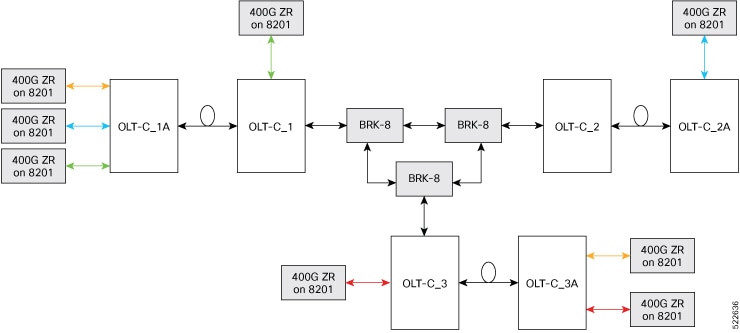
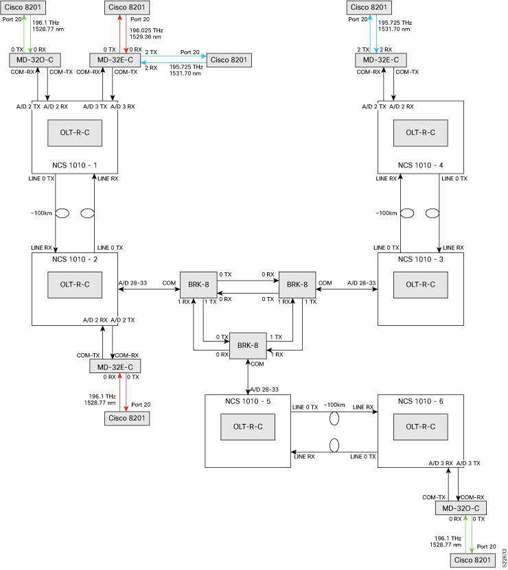
Figure 1. Typical 3-Degree topology
Figure representing typical 3-degree topology

Types of NCS 1010 sample topologies

This section describes three sample topologies of specific hardware deployments.

Colored multidegree topologies

A colored multidegree topology is a network design pattern that

  • interconnects sites using multiple optical degrees,

  • supports optical channels from transponders with low transmit (TX) power such as ZR or ZR+ pluggable modules, and

  • operates with channel TX power spectral density between -21 dBm/12.5 GHz and -14 dBm/12.5 GHz.

Topology components

This topology typically requires:

  • Cisco NCS 1010 devices

  • NCS1K-MD32E-C modules

  • NCS1K-MD32O-C modules

  • NCS1K-BRK-8 modules

  • Cisco 8201 routers

  • QDD-400G-ZR-S transceivers

  • LC/LC cables

  • MPO cables

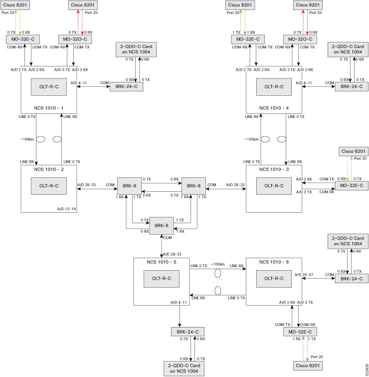
Figure 2. Colored solution
A diagram representing the colored multidegree topology with devices and port connections

Colorless multidegree topologies

A colorless multidegree topology is a network design pattern that

  • uses multi-degree site interconnections with flexible wavelength assignment,

  • supports optical channels from high TX power transponders like 1.2T line cards or CFP2-400G-DCO trunk interfaces, and

  • requires channel TX power spectral density not lower than -7 dBm/12.5 GHz.

Components required

Deployment typically includes:

  • Cisco NCS 1010 devices

  • NCS1K-BRK-8 modules

  • NCS1K-BRK-24 modules

  • CFP2-400G-DCO transceivers

  • Cisco NCS 1004 devices

  • NCS1K4-2-QDD-C-K9 line card

  • LC/LC cables

  • MPO cables

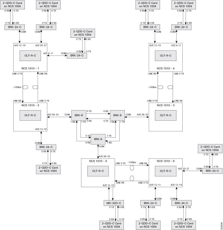
Figure 3. Colorless solution
A diagram representing the colorless multidegree topology with devices and port connections

Hybrid multidegree topologies

A hybrid multidegree topology is a network design pattern that

  • interconnects sites using both colored and colorless optical channels,

  • accommodates a mix of high- and low-TX power transponders within the same deployment, and

  • leverages the channel TX power spectral density ranges required for both colored and colorless topologies.

Components required

Supported hardware includes:

  • Cisco NCS 1010 devices

  • NCS1K-MD32E-C modules

  • NCS1K-MD32O-C modules

  • NCS1K-BRK-8 modules

  • NCS1K-BRK-24 modules

  • Cisco 8201 routers

  • QDD-400G-ZR-S transceivers

  • CFP2-400G-DCO transceivers

  • Cisco NCS 1004 devices

  • NCS1K4-2-QDD-C-K9 line card

  • LC/LC cables

  • MPO cable

Figure 4. Colorless solution
A diagram representing the hybrid multidegree topology with devices and port connections

Point-to-point topologies

A point-to-point topology is a network design pattern that

  • connects two network sites directly using optical links,

  • limits the number of degrees per site to two or fewer, and

  • enables simple deployment with minimal hardware requirements.

Components for point-to-point topology

To build this topology, you need these hardware components.

  • Cisco NCS 1010 devices: OLT-R-C for and ILA-2R-C for inline amplication

  • NCS1K-MD32E-C modules: Multiplex and demultiplex C-band signals in even channels.

  • NCS1K-MD32O-C modules: Multiplex and demultiplex C-band signals in odd channels.

  • NCS1K-BRK-24 modules: 24-degree MPO breakout modules for express interconnection.

  • QDD-400G-ZR-S transceiver: QSFP-DD transceiver module, coherent DCO, 400G-ZR for transmiting 400G payload at 16QAM modulation

  • MPO/MPO cables: Used for fiber-optic connectivity between NCS 1010 devices and BRK-24 modules.

  • LC/LC cables: Used for fiber-optic connectivity between BRK-24 and mux/demux modules.

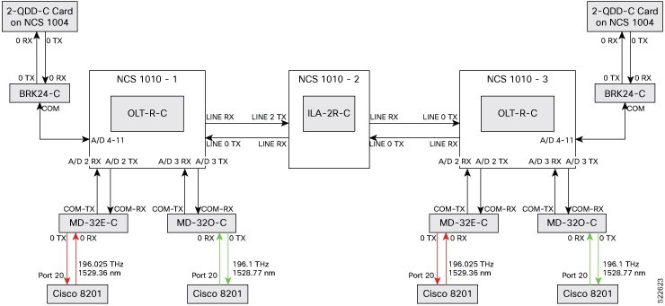
This image shows the point-to-point topology.

Figure 5. Point-to-point topology
A diagram representing the point-to-point topology with the devices and port connections