Cisco NCS 1010 and NCS 1020 Datapath Configuration Guide, IOS XR Releases 26.x.x

PDF

ASE loading

Want to summarize with AI?

Log in

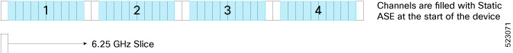
This section explains how ASE loads are used to stabilize optical transmission systems by filling the spectrum when channels are unavailable.


The OLT card (both OLT-C and OLT-L) includes a Noise Loader (NL) EDFA, which acts as an Amplified Spontaneous Emission (ASE) or noise source. The NL connected to the 2x33 ports Wavelength Selective Switch (WSS) loads optical noise. The optical noise fills the Line-TX optical spectrum, when the provisioned optical channels are not available on the ADD- 1 RX, ADD- 2 RX, or COM (OTS0/0/0/2 - OTS0/0/0/33) ports. For more details about the ports, see OLT Functional Layout.

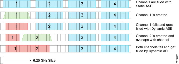
The CHANNEL-NOISE-LOADED alarm is raised when an OTS-OCH controller channel fails and the missing carrier power in the channel is replaced with internally generated ASE noise. The alarm is cleared automatically when the original traffic channel is restored and the temporary ASE noise is removed. For more details about the alarm, see CHANNEL-NOISE-LOADED.

Benefits of ASE loading:

  • Completely populates the transmission spectrum at LINE-TX independent of the actual system traffic load, thereby easing the system regulation starting from the Day-1 of the installation.

  • The same channel load is maintained during channel failures or channel deletion, which makes the system tolerant to power transients.

  • System performances can be verified efficiently because the ASE pattern emulates the full spectrum load also for the nonlinear interaction in the fibers, such as Four Wave Mixing (FWM), Cross Phase Modulations (XPM), and Stimulated Raman Scattering (SRS). Also, gradual fiber degradation that affects utilization of full-fiber capacity can be tracked.

  • Keeps the system running the full-channel configuration, which makes the system be intrinsically stable and provide optimal performance.


How ASE operates

These operations are performed as part of the ASE loading:

  1. The NL emits a total power of 16 dBm, and generates a power-spectral density (PSD) that is approximately equal to –10 dBm/12.5 GHz at the WSS input port. The OCM7 port monitors profile of the generated ASE channel. A Variable Optical Attenuator (VOA) available between the NL and the WSS input port regulates the ASE channel level properly.

  2. The controller sets a predefined value for the VOA so that the ASE channels that are obtained at the COM TX-1 port are equalized to the actual traffic channels to fill out the spectrum at the input of the fixed gain amplifier.

  3. When the controller detects a missing channel, for example any failure on the ADD/ EXP ports, it sends an updated attenuation value to the OLT. The OLT applies this value as a new attenuation setpoint and executes the transition from ADDs/EXPs path to ASE in the impacted wavelengths, thus ensuring fast recovery of the initial total optical power on the LINE-TX port.

  4. When the optical power is restored, the controller sends a restoration command to the OLT. The OLT executes the transition from ASE to ADDs/EXPs in the impacted wavelengths ensuring minimal total optical power disturbance on the LINE-TX port, thus allowing a smooth fade-out of the ASE.


How ASE Is managed

The default target ASE Load Spectral Density (AL_SD) is set to 81% for the OLT-C card and 78% for the OLT-L card. This default AL_SD is defined based on the frequency grid at 75 GHz with the first channel centered at 191.375 THz for OLT-C card and 186.125 THz for the OLT-L card. The spectrum is allocated through logical bins with 3.125-GHz width such that each physical slice is associated to two bins. Based on the above, the first ASE channel for the OLT-C card has:

  • Bins 1 and 2 blocked (frequency range 191.33750 – 191.34375 THz)

  • Bins 3–22 opened (frequency range 191.34375 to 191.40625 THz)

  • Bins 23 and 24 blocked (frequency range 191.40625 – 191.4125 THz)

The first ASE channel for the OLT-L card has:

  • Bins 13 and 14 blocked (frequency range 186.0875 – 186.09375 THz)

  • Bins 15–34 opened (frequency range 186.09375 to 186.15625 THz)

  • Bins 35 and 36 blocked (frequency range 186.15625 – 186.1625 THz)

All the other ASE channels are defined similarly by shifting all the settings by 75 GHz (24 bins).

Note

The ASE channels on the bins 1537–1548 and 1-12 are retained as blocked for Automatic VOA Shutdown (AVS) for the OLT-C and OLT-L cards respectively. In this AVS mode, the VOA is set at maximum attenuation value, when the channel is not provisioned to ensure the system reliability in case power is accidentally inserted.

Static ASE—At the system startup, without any channel provisioned, the complete ASE Load pattern is forwarded to the OLT LINE-TX port.

Figure 1. Static ASE

Dynamic ASE—When a traffic channel fails (for example, the PSD within the set of slices that are dedicated to the traffic channel is below a given threshold) an equivalent temporary ASE channel is inserted to maintain the spectral density on the line port. This dynamic ASE channel fills the original traffic channel with only a single slice guard band, at the beginning and the end. When the original traffic channel is restored, the temporary ASE channel is removed, and the original routing on the WSS is reestablished.

Dynamic ASE—With the Nyquist channels, dynamic ASE has these behavior changes:

  • A minimum guard band of 6.25GHz is maintained between the active channel and the dynamic ASE, so the guard band of dynamic ASE will be 6.25 GHz + unused portion of the next user channel.

  • When there are two channels, and if channel 1 has failed and channel 2 overlaps channel 1, the dynamic ASE is filled in the slices other than the overlapping slices while leaving at least one slice as guard band.

  • If both channel 1 and channel 2 are overlapping and both have failed, dynamic ASE fills both the channels without leaving any guardband.

  • Static ASE and Dynamic ASE cannot overlap.

Figure 2. Dynamic ASE with Nyquist Channels

ASE loading disable

Table 1. Feature History

Feature Name

Release Information

Description

ASE Loading Disable

Cisco IOS XR Release 26.1.1

ASE loading can be disabled at both the channel and module levels to improve troubleshooting capabilities. The "ASE Loading Disabled" alarm has been introduced for this feature.

Commands modified:

The keyword ase-loading disable has been added to these commands:

  • hw-module location location terminal-ampli

  • hw-module location location terminal-ampli grid-mode flex channel id<id>

You can now disable ASE loading for improved troubleshooting. Disabling ASE loading at the channel level raises an 'ASE Loading Disabled' alarm on the OTS-OCH interface. Disabling ASE loading at the spectrum level raises the 'ASE Loading Disabled' alarm on the OTS interface.

If both channel-level and spectrum-level configurations are present to disable ASE loading, only the spectrum-level alarm raises.

Note

ASE Loading Disable is not supported on ILA Node.


Configuring ASE loading disable at spectrum level

Use this procedure to configure ASE loading disable feature and verify the configuraiton at spectrum level.

Before you begin

  • Before disabling ASE loading, APC must be paused on all the nodes.

Procedure

Use this sample configuration to enable ASE loading disable feature at spectrum level.

Example:

RP/0/RP0/CPU0:ios#config
RP/0/RP0/CPU0:ios(config)#hw-module location 0/0/NXRO terminal-ampli
RP/0/RP0/CPU0:ios(config)#ase-loading disable
RP/0/RP0/CPU0:ios(config)#commit
RP/0/RP0/CPU0:ios(config)#end
Use this configuration to verify whether ASE loading is disabled at spectrum level.
show running-config hw-module location 0/0/NXR0 terminal-ampli
 ase-loading disable

Remove ASE loading disable at spectrum level

Procedure

Use this sample configuration to remove ASE loading disable feature at spectrum level.

Example:

RP/0/RP0/CPU0:ios#config
RP/0/RP0/CPU0:ios(config)#hw-module location 0/0/NXRO terminal-ampli
RP/0/RP0/CPU0:ios(config)#no ase-loading disable
RP/0/RP0/CPU0:ios(config)#commit
RP/0/RP0/CPU0:ios(config)#end

Configure ASE loading disable at channel level

Configure ASE loading disable and verify the configuraiton at channel level.

Before you begin

Before disabling ASE loading, APC must be paused on all the nodes.

Procedure

Use this sample configuration to remove the ASE loading disable feature at the channel level.

Example:

RP/0/RP0/CPU0:ios#config
RP/0/RP0/CPU0:ios(config)#hw-module location 0/0/NXRO terminal-ampli
RP/0/RP0/CPU0:ios(config)#grid-mode flex
RP/0/RP0/CPU0:ios(config)#channel-id 1 ase-loading disable
RP/0/RP0/CPU0:ios(config)#channel-id 1 centre-freq 193.123 width 75
RP/0/RP0/CPU0:ios(config)#commit
RP/0/RP0/CPU0:ios(config)#end
Use this configuration to verify wheter ASE loading is disabled at channel level.
show running-config hw-module location 0/0/NXR0 terminal-ampli grid-mode flex channel-id

Remove ASE loading disable at channel level

Remove ASE loading disable at channel level.

Procedure

Use this sample configuration to disable the ASE loading disable feature at the channel level.

Example:

RP/0/RP0/CPU0:ios#config
RP/0/RP0/CPU0:ios(config)#hw-module location 0/0/NXRO terminal-ampli
RP/0/RP0/CPU0:ios(config)#grid-mode flex
RP/0/RP0/CPU0:ios(config)#no channel-id 1 ase-loading disable
RP/0/RP0/CPU0:ios(config)#commit
RP/0/RP0/CPU0:ios(config)#end