Overview
This topic explains how band failure recovery (BFR) operates in various network fault scenarios. It outlines the procedures BFR follows, the conditions required for recovery, and the expected outcomes in each situation.
After the optical fiber fault is cleared, BFR starts the recovery procedure on each failed band node individually. BFR also ensures that traffic is not impacted.
Band failure recovery
After the optical fiber fault is cleared, BFR starts the recovery procedure on the failed band nodes one at a time. BFR also ensures that traffic is not impacted. The PSD profiles on the recovered and surviving bands are switched to dual-band PSD profiles.
Recovery procedure is initiated only if all the nodes (both C-band and L-band) are active and reachable.
BFR runs the recovery procedure on the failed band while APC shifts the PSD profiles. APC must be enabled on both C and L-band devices for BFR to work. We recommend pausing BFR before running the apc-pause or apc disable commands.
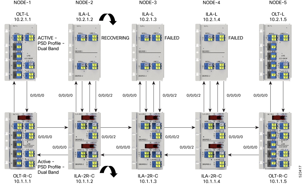
This figure shows how BFR recovers from an L-band failure. After the fiber fault is cleared, BFR starts recovery on all C and L-band nodes one node at a time. The recovery procedure on Node 1 is completed and the status is shown as ACTIVE. The recovery procedure on Node 2 is in progress, so the node status is shown as RECOVERING. BFR starts recovery on each remaining node, one at a time, after recovering Node 2.
This example shows the C and L-band status as RECOVERING on the 192.0.2.1 node:
RP/0/RP0/CPU0:#show olc band-status
Controller              : Ots0/0/0/0
Self-Band               : C-Band
BFR status              : Running
Node RID                : 10.1.1.1
Self IP Address     : 192.0.2.1
Self Controller         : Ots0/0/0/0
Partner IP address      : 192.0.2.2
Partner Controller      : Ots0/0/0/0
Partner link status     : UP
C-Band status           : ACTIVE
C-Band PSD              : Dual Band
L-Band status           : ACTIVE
L-Band PSD              : Dual Band
Node RID                : 10.1.1.2
Self IP Address     : 192.0.2.21
Self Controller         : Ots0/0/0/0
Partner IP address      : 192.0.2.22
Partner Controller      : Ots0/0/0/2
Partner link status     : UP

C-Band status           : RECOVERING

C-Band PSD              : NA

L-Band status           : RECOVERING

L-Band PSD              : NA
Node RID                : 10.1.1.3

Self IP Address         : 192.0.2.31
Self Controller         : Ots0/0/0/0
Partner IP address      : 192.0.2.32
Partner Controller      : Ots0/0/0/2
Partner link status     : UP
C-Band status           : ACTIVE
C-Band PSD              : Single Band
L-Band status           : FAILED
L-Band PSD              : NA
Node RID                : 10.1.1.4

Self IP Address         : 192.0.2.41
Self Controller         : Ots0/0/0/0
Partner IP address      : 192.0.2.42
Partner Controller      : Ots0/0/0/0
Partner link status     : UP
C-Band status           : ACTIVE
C-Band PSD              : Single Band
L-Band status           : FAILED
L-Band PSD              : NA
Node RID                : 10.1.1.5

Self IP Address         : 192.0.2.51
Self Controller         : Ots0/0/0/0
Partner IP address      : 192.0.2.52
Partner Controller      : Ots0/0/0/0
Partner link status     : UP
C-Band status           : ACTIVE
L-Band status           : FAILED
Single band failure recovery on non-Raman network
After the optical fiber fault is cleared, BFR performs these operations for single band failure on a non-Raman network.
-
Starts recovery on the failed band one node at a time.
-
After the recovery is completed and both bands are active, BFR switches the PSD profiles on both bands to dual-band PSD.
Span failure recovery
On a C and L band network, when both bands fail, BFR does not change the PSD profile to single-band PSD. After the failure is cleared, both bands recover quickly.
When a span failure is cleared on a Raman network and Raman tuning is disabled, BFR starts recovery of nodes. If Raman tuning is enabled, BFR suspends recovery and resumes it only after Raman tuning is completed.
Single band failure recovery on a Raman network
On a C+L band network without Raman amplifiers, when a band fails, Loss of Signal (LOS) is reported because the total power drops below the safe value. This shuts down the amplifiers on other nodes. If a band fails on the near end node of a Raman network, the far end amplifiers receive some band power because of ASE. In this case, LOS is not reported and the amplifiers on far end nodes remain active. BFR ensures that recovery on the far end nodes is started even if the amplifiers on the nodes are active because of ASE and sets safe mode on the failed band.
Once the optical fiber fault is cleared on a Raman network, if Raman tuning is started, BFR suspends recovery and resumes it only after Raman tuning is completed. If Raman tuning is not started, BFR starts the recovery of nodes one by one.
Band failure recovery due to device in headless mode
In the event of a band failure on a network with an OLT device in headless mode, BFR performs these operations.
-
BFR does not switch the PSD profile to single-band PSD.
-
BFR does not run the recovery procedure.
In the event of a band failure on a network with an ILA device in headless mode, BFR performs these operations.
-
BFR switches the PSD profile to single-band PSD on all the nodes that are reachable by C-band OLT.
-
BFR does not run the recovery procedure on all the OLT and ILA nodes.
-
If one or more nodes on the network are in headless mode, BFR is not initiated, which might affect traffic recovery. Perform these tasks to restore traffic:
For more information about these commands, see the Command Reference for Cisco NCS 1010 Guide.
Band failure recovery due to partner link status
On a C+L band network, if there is a connectivity failure between the C-band and L-band ILA nodes, BFR does not start the recovery procedure. If the recovery procedure is running and the Partner link status is DOWN, BFR suspends recovery and resumes it after the Partner link status changes to UP.
This example shows the output of the show olc band-status command with Partner link status status set to UP.
                RP/0/RP0/CPU0:#show olc band-status
Controller              : Ots0/0/0/0
Self-Band               : C-Band
BFR status              : Running
Node RID                : 10.1.1.1

Self IP Address         : 192.0.2.1
Self Controller         : Ots0/0/0/0
Partner IP address      : 192.0.2.2
Partner Controller      : Ots0/0/0/0
Partner link status     : UP
C-Band status           : ACTIVE
C-Band PSD              : Dual Band
L-Band status           : ACTIVE
L-Band PSD              : Dual Band