Overview
This topic explains how span losses in optical networks are measured, reported, and used to monitor the integrity of fiber spans between network nodes.
A span loss is an optical network measurement that
-
determines the signal power loss between two nodes in an optical transmission network,
-
compares the power measurements at transmitter (Tx) and receiver (Rx) ports at the near and far ends of a fiber span, and
-
automatically raises the Span Loss Value Out Of Range alarm when the calculated loss does not fall within configured thresholds.
On a Raman span with Raman tuning enabled, span loss verification reports these values:
-
Span loss with pumps off: This measurement is the difference in power values between the DFB-Tx/Rx of the remote node and the DFB-Rx/Tx of the local node. This measurement also includes a timestamp. When a Raman span is up, the span loss application latches on to the difference in power between DFB-Tx and DFB-Rx before Raman tuning turns the Raman pumps on.
-
Apparent span loss: This measurement is based on the power values of C band, L band and Optical Service Channel (OSC). For a Raman span, the span loss application uses this span loss value to raise the Span Loss Value Out Of Range alarm.
-
Estimated span loss: This value is based on Raman gain that is achieved by Raman tuning application. Estimated span loss value is based on Raman gain that is achieved when safety loop was closed and tuning was performed. Raman tuning application reports the Raman gain measurement. When you disable Raman tuning, the span loss application does not compute the Estimated span loss.
Estimated span loss = Apparent span loss + Raman gain
-
OSC span loss: This measurement is the difference in OSC power values between the Tx/Rx of the remote node and the Rx/Tx of the local node.
-
Signal span loss: This measurement is the difference in the received C band signal power values between the Tx/Rx of the remote node and the Rx/Tx of the local node.
Span loss calculations are performed automatically between nodes to continuously monitor the condition of the optical span. The span loss application reports the span loss value for a span every 90 seconds. If span loss changes, for example when a change in fiber loss occurs, the span loss application typically takes 90 seconds to update the span loss.
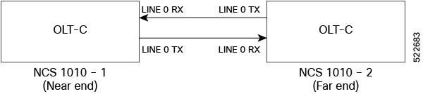
For example, in the previous figure, the Tx Span Loss on NCS 1010-1 is the difference in signal power between LINE 0 TX on NCS 1010-1 and LINE 0 RX on NCS 1010-2.