Cisco Optical Automation Solution Workflow, IOS XR Release 26.1.1

PDF

Cisco Optical Automation Solution Workflow, IOS XR Release 26.1.1

Install Cisco NCS 1010, NCS 1014, and NCS 1004 hardware

Want to summarize with AI?

Log in

Use this procedure to install Cisco NCS 1010, NCS 1014, and NCS 1004 hardware. It helps you complete power, fiber, and passive connections for the Optical Access System workflow.


Prepare the hardware so it is ready for initial configuration.

Use these hardware-installation tasks in sequence. Each linked procedure is kept as a separate task step in the child topics.

Before you begin

Verify that the rack, power, grounding, hardware placement, cabling, and passive-connection details meet the site design and Cisco installation requirements.

Procedure

1.

Prepare and install the NCS 1010 chassis and required modules for the site.

2.

Connect the NCS 1010 chassis to the approved site power feed.

For more details, see Connect power to the NCS 1010.

3.

Install the NCS 1010 passive modules and breakout hardware from the site design.

For more details, see Install NCS 1010 passive modules.

4.

Prepare and install the NCS 1014 chassis and required modules for the site.

5.

Install NCS 1014 power components, pluggables, and air-filter hardware.

6.

Prepare and install the NCS 1004 chassis in the site rack.

For more details, see Install the NCS 1004 chassis.

7.

Install the NCS 1004 controller and line cards required by the bill of materials.

8.

Install the NCS 1004 FRUs, pluggables, air filter, and fiber-management hardware.

9.

Connect NCS 1004 power and complete final fiber and passive connections.

All hardware is installed and ready for console access and initial configuration.
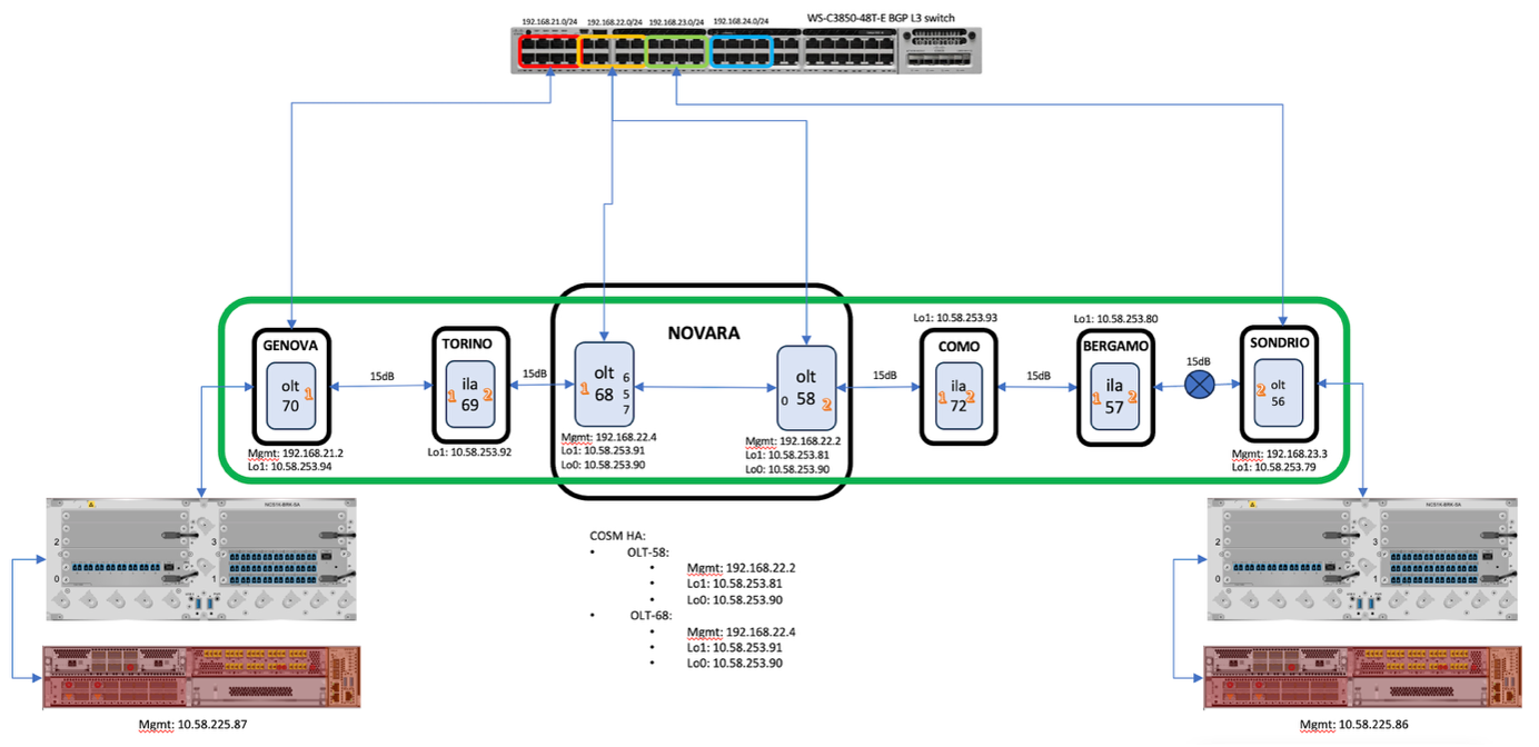

NCS 1000 platform prerequisites

Collect the required addressing and host information for each node in the topology.

Required details to gather before installation for each node in the topology.

  • Hostname for each node.

  • Management and loopback IP addresses.

  • Indicate the node role, such as OLT, ILA, OLA, or transponder shelf.

  • DCN plans to ensure proper management connectivity.

  • Access to servers such as NTP, TACACS, and Smart Licensing for software downloads.

Figure 1. Sample topology addressing
Table 1. Sample topology addressing

Node type

Hostname

Mgmt0 IP

Mgmt2 IP

Loopback1 IP

(OSC/COSM)

Loopback0 IP

(COSM- HA)

NCS1K-OLT-C

onc-oltc-225-70

10.58.225.70

192.168.21.2

10.58.253.94

NCS1K-ILA-C

onc-ilac-225-69

10.58.225.69

10.58.253.92

NCS1K-OLT-C

onc-oltc-225-68

10.58.225.68

192.168.22.4

10.58.253.91

10.58.253.90

NCS1K-OLT-C

onc-oltc-225-58

10.58.253.58

192.168.22.2

10.58.253.81

10.58.253.90

NCS1K14

onc-kepler-225-87

10.58.225.87

NCS1K04

onc-bh-225-93

10.58.225.93

Management interface requirements

This table describes the data that must be confirmed before installation, along with its status and related notes.

Table 2. Data to confirm before installation

Item

Status

Notes

IP plan

Complete

Validated with design team

Hostname list

Complete

Aligned with naming standards

Note

Adjust the addressing table to match the customer topology.


Install the NCS 1010 chassis and modules

Install the NCS 1010 chassis and field-replaceable modules required for the site.

Complete these procedures before applying site power or completing passive-module connections.

Before you begin

Verify rack space, grounding, and site installation readiness for NCS 1010.

Procedure

1.

Verify rack space, grounding, airflow, tools, and safety requirements before installing Cisco NCS 1010.

For more details, see Prepare to install Cisco NCS 1010.

2.

Mount the Cisco NCS 1010 chassis in the approved EIA, ANSI, or ETSI rack.

3.

Install the required Cisco NCS 1010 modules in their assigned chassis slots.

For more details, see Install Cisco NCS 1010 modules.

4.

Insert and seat the NCS 1010 power supply unit in the assigned slot.

For more details, see Install PSU.

5.

Install and secure the NCS 1010 controller card.

For more details, see Install controller.

6.

Install and secure the required NCS 1010 line card.

For more details, see Install line card.

7.

Install the fan tray and confirm it is fully seated.

For more details, see Install fan tray.

8.

Install the fan filter after the fan tray is in place.

For more details, see Install fan filter.

9.

Install the protection cover as required by the hardware procedure.

For more details, see Install the protection cover.

The NCS 1010 chassis and modules are installed.


Connect power to the NCS 1010

Connect AC or DC power to the NCS 1010 chassis.

Select the procedure that matches the power design for the site.

Before you begin

Install the NCS 1010 chassis, PSU, and required protection hardware.

Procedure

1.

Connect the NCS 1010 chassis to the approved AC power source when the site uses AC feeds.

For more details, see Connect AC power to Cisco NCS 1010.

2.

Connect the NCS 1010 chassis to the approved DC power source when the site uses DC feeds.

For more details, see Connect DC power to Cisco NCS 1010.

Power connections for NCS 1010 are complete.


Install NCS 1010 passive modules

Install passive modules and breakout patch panels according to the site design.

Confirm module placement, port labels, and LED states before completing fiber connections.

Before you begin

Review the CONP design for required passive modules and breakout patch panels.

Procedure

1.

Identify the breakout patch panels and passive modules required for the NCS 1010 site.

2.

Install the Cisco NCS 1000 breakout patch panel in the planned location.

For more details, see Cisco NCS 1000 breakout patch panel.

3.

Install the Cisco NCS 1000 breakout modules required by the site design.

For more details, see Cisco NCS 1000 breakout modules.

4.

Match breakout module port labels to the cabling plan before connecting fibers.

5.

Check breakout module LED states after installing and cabling the passive modules.

For more details, see Breakout module LEDs.

NCS 1010 passive module references are reviewed and the passive hardware can be installed according to the site design.


Install the NCS 1014 chassis and modules

Install the NCS 1014 chassis and core modules required for the OAS site.

Complete these procedures before power, pluggable, and air-filter installation.

Before you begin

Verify rack, power, grounding, and fiber-management readiness for NCS 1014.

Procedure

1.

Mount the Cisco NCS 1014 chassis in the approved EIA, ANSI, or ETSI rack.

2.

Confirm NCS 1014 power and grounding requirements before installing powered components.

3.

Attach the fiber management bracket to the slider rail before routing fibers.

4.

Install the SSD in the NCS 1014 chassis.

For more details, see Install the solid state drive (SSD).

5.

Install the fan unit and confirm it is fully seated.

For more details, see Install the fan unit.

6.

Install and secure the NCS 1014 controller.

For more details, see Install the controller.

7.

Attach the fiber management bracket for the installed module layout.

For more details, see Attach the fiber management bracket.

8.

Adjust the fiber management bracket for the planned fiber routing.

For more details, see Adjust the fiber management bracket.

9.

Install and secure the required NCS 1014 line card.

For more details, see Install the line card.

The NCS 1014 chassis and core modules are installed.


Complete NCS 1014 power, pluggables, and air-filter installation

Complete the remaining NCS 1014 hardware installation after the chassis and core modules are installed.

Select the AC or DC power procedure that matches the site design.

Before you begin

Install the NCS 1014 chassis, controller, fan unit, and line cards.

Procedure

1.

Install the NCS 1014 power supply units in the assigned slots.

For more details, see Install the power supply units (PSUs).

2.

Connect the NCS 1014 chassis to the approved DC power source when the site uses DC feeds.

3.

Connect the NCS 1014 chassis to the approved AC power source when the site uses AC feeds.

4.

Install the required pluggables in the NCS 1014 ports.

For more details, see Install the pluggables.

5.

Install the NCS 1014 air filter after module installation is complete.

For more details, see Install the air filter.

NCS 1014 power, pluggables, and air-filter installation is complete.


Install the NCS 1004 chassis

Install the NCS 1004 chassis according to site rack and grounding requirements.

Complete chassis installation before installing controllers, line cards, and field-replaceable units.

Before you begin

Verify rack compatibility, grounding, and power-feed readiness for NCS 1004.

Procedure

1.

Confirm that the site rack supports the NCS 1004 chassis before installation.

For more details, see Rack compatibility.

2.

Mount the NCS 1004 chassis in the approved EIA, ANSI, or ETSI rack.

3.

Apply the NCS 1004 stacking requirements if multiple chassis share the rack space.

For more details, see Stacking NCS 1004.

4.

Confirm NCS 1004 power and grounding requirements before installing powered components.

5.

Verify the NCS 1004 power supply type against the site power design.

For more details, see Power supply.

The NCS 1004 chassis is installed and ready for module installation.


Install NCS 1004 controller and line cards

Prepare and install the NCS 1004 controller and supported line-card hardware.

Use the line-card-specific references that match the hardware in the site bill of materials.

Before you begin

Install the NCS 1004 chassis.

Procedure

1.

Review the NCS 1004 module installation sequence before inserting cards.

For more details, see Install Cisco NCS 1004 modules.

2.

Confirm that the controller card is supported for the NCS 1004 chassis.

For more details, see Supported controller cards.

3.

Install and secure the NCS 1004 controller card.

For more details, see Install controller.

4.

Identify the NCS 1004 line-card type required by the site bill of materials.

For more details, see About line cards.

5.

Use the 1.2T line-card requirements when the site includes a 1.2T card.

For more details, see 1.2T line card.

6.

Use the 1.2TL line-card requirements when the site includes a 1.2TL card.

For more details, see 1.2TL line card.

7.

Use the 2-QDD-C line-card requirements when the site includes a 2-QDD-C card.

For more details, see 2-QDD-C line card.

8.

Use the OTN-XP line-card requirements when the site includes an OTN-XP card.

For more details, see OTN-XP line card.

9.

Use the QXP-K9 line-card requirements when the site includes a QXP-K9 card.

For more details, see QXP-K9 line card.

The NCS 1004 controller and line-card references are complete for the installed hardware.


Install NCS 1004 field-replaceable units and fiber management

Complete NCS 1004 module, field-replaceable unit, pluggable, air-filter, and fiber-management installation.

Use the fiber-management procedure that matches the installed line-card type.

Before you begin

Install the NCS 1004 chassis and identify the installed line-card type.

Procedure

1.

Insert and secure the selected NCS 1004 line card in the assigned slot.

For more details, see Install line card.

2.

Install the NCS 1004 power supply in the assigned slot.

For more details, see Install power supply.

3.

Install the fan unit and confirm it is fully seated.

For more details, see Install fan unit.

4.

Attach the fiber management bracket before routing fibers to the line cards.

For more details, see Attach fiber management bracket.

5.

Adjust fiber management for installed 1.2T, 1.2TL, 2-QDD-C, or QXP-K9 line cards.

6.

Adjust fiber management for an installed OTN-XP line card.

7.

Install the required pluggables in the NCS 1004 ports.

For more details, see Install pluggables.

8.

Confirm the NCS 1004 air-filter requirements for the installed chassis.

For more details, see Air filter.

9.

Install the NCS 1004 air filter.

For more details, see Install air filter.

The NCS 1004 field-replaceable units, pluggables, air filter, and fiber-management hardware are installed.


Connect NCS 1004 power and complete passive connections

Complete NCS 1004 power connections and final OAS fiber and passive connections.

Complete all fiber and port connections according to the network design. Use the Brk-8 module for internal degree connections when required. Based on the design, internal degree connections can also be established directly through LC ports instead of through the Brk-8 module.

Before you begin

Install the required NCS 1004 modules and review the CONP design output for site passive connections.

Procedure

1.

Connect the NCS 1004 chassis to the approved DC power source when the site uses DC feeds.

For more details, see Connect DC power to NCS 1004.

2.

Connect the NCS 1004 chassis to the approved AC power source when the site uses AC feeds.

For more details, see Connect AC power to NCS 1004.

3.

Use the CONP NFV and connection reports to complete passive and fiber connections.

NCS 1004 power and final site passive connections are complete.

What to do next

Proceed to day-0 configuration for each node.