This section provides details about plan your NCS1010 Network. Use it to understand the related Optical Automation Solution workflow information.
Plan an NCS 1010-based network using Cisco Optical Network Planner to design a topology with the required specifications, analyze it, and generate planning data. For detailed instructions, see Design and Analyze Networks.
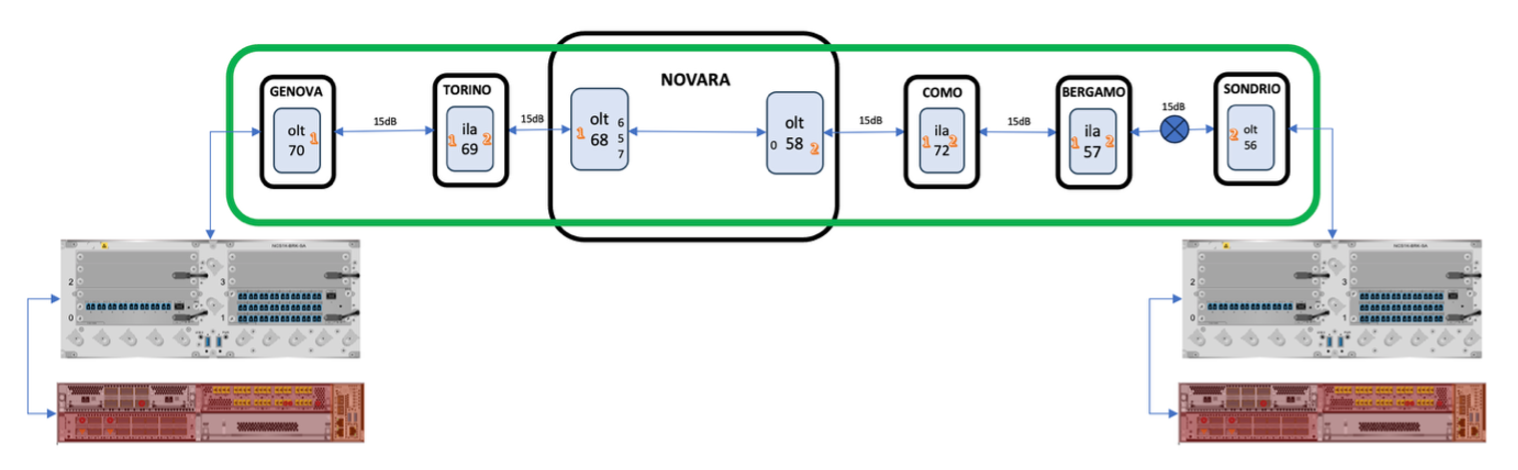
This reference network topology described here illustrates these NCS 1010 bring-up scenarios.
It is a two-degree topology that uses seven NCS 1010 nodes.
The BRK-8 modules are used to create express interconnect in Site-Novara using MPO cables.
Figure 1. Multi-degree Topology
Design the topology in Cisco Optical Network Planner
Use this procedure to create a Cisco Optical Network Planner model that matches the physical design for a new region or pilot network.
The output is a topology file that you can use for Cisco Optical Site Manager exports and downstream bill of materials validation.
The sample node names (Genova, Novara, Sondrio, Torino, Como, Bergamo) correspond to the reference network and should be adapted as necessary.
Consider these inputs before you create the network plan. Apply them according to your network design requirements.
Create the number of circuits based on the channel plan and use the appropriate card type for each circuit.
Force the add/drop type according to the design requirements. For details about add/drop configuration, see Modify Network Properties.
Before you begin
Confirm licensing for Cisco Optical Network Planner and verify that your account can create and save projects.
Gather topology notes: number of ROADM and OLA sites, fiber lengths, and circuit/service requirements.
Clarify whether the design needs colored or colorless add/drop behavior per site.
Follow these steps to design the topology.
Procedure
1.
Create the base network in Cisco Optical Network Planner.
Log in to the Cisco Optical Network Planner home page with a valid user.
Choose File, then click New.
In Create New Network dialog box, set L0 Network Platform to NCS 1010 and Band Type to C-Band.
You can set the system release values as follows:
Platform
System Release
NCS 1010
26.1.1
NCS 1014
26.1.1
NCS 1004
25.4.1
Name the network consistently with your deployment tracker (for example, REGION_TOPOLOGY_MMDD).
A new, empty network canvas opens with the drawing tool enabled.
2.
Follow these steps to add sites, fibers, circuits, and services with the drawing tool.
Click the Drawing Tool icon (pencil and ruler).
Add ROADM and OLA sites (for example, ROADM: Genova, Novara, Sondrio; OLA: Torino, Como, Bergamo).
Use the Fiber tool to connect sites following the target topology.
Click on the source site and then the destination site in the map to select Circuit (purple) to add demands.
Both Alien and NCS1000 TXP Trunk to Trunk demands can be created with this option.
Select Service (green) to create client services of native NCS1000 TXP.
The service automatically creates a trunk-to-trunk circuit.
Note
For the specified topology, create a circuit, a service, or both. Define at least one before you run an analysis.
The visual topology reflects the required sites, fibers, circuits, and services.
3.
Follow these steps to set site properties using Entity Editor.
Choose Network, then click Entity Editor.
Under Site, then click Name, rename the ROADM and OLA nodes.
Add the NCS 1010 Line Card property value as Enhanced Faceplate or Standard Faceplate.
By default, Enhanced Faceplate is selected.
For OLA nodes, set Functionality, then click Line amplifier within the C-Band section.
Drill down into Fibers to update Fiber Type, Aging Loss, and SOL Loss values.
Update the fiber values in Properties.
Click Show Advance properties to update advanced parameters.
Expand Subnet, then click OpticalSubnet and adjust spectral density (for example, Flexgrid-SD-81%).
Keep a change log of any forced parameters so installers know which passives to deploy.
By default fibers are 1 km. Enable Use Coordinates Distance under Network Properties if you want lengths derived from coordinates.
To apply Raman amplification, expand a site to C-band and set Raman Amp accordingly.
Sites, fibers, and subnet properties match the physical design data.
4.
Optional: To select specific colored Add/drop MD-32-E/MD-32-O Mux/Demux patch panels based on the topology, set these properties.
Note
If you do not force this setting and leave it set to Auto, Cisco Optical Network Planner automatically selects the default Add/drop.
Choose Network, click Entity Editor, and then click the Service tab.
In the left tree panel, expand the circuit that connects to the site where the patch panel is connected, and then drill down to the trail properties.
Under the trail properties, set Add/Drop Type to Colored.
Click Select Similar to apply the properties in bulk to all the trails.
Click Update.
Click the Site tab.
Expand the ROADM site interface, drill down to the Add/Drop properties of the side, and then under General, set Colored Add/Drop to MD-32-Even or MD-32-Odd as per the topology.
Click Select Similar to apply the properties in bulk to all the add/drops.
Click Update.
5.
Optional: To select specific BRK-24 and BRK-8 breakout panels, set these properties.
Note
If Auto is selected, Cisco Optical Network Planner automatically selects the default Add/drop.
Choose Network, click Entity Editor, and then click the Service tab.
In the left tree panel, expand the circuit that connects to the site where the breakout panel is connected, and then drill down to the trail properties.
Under the trail properties, set Add/Drop Type to Colorless.
Click Select Similar to apply the properties in bulk to all the trails.
Click Update.
Click the Site tab.
Expand the site interface, drill down to the Add/Drop properties of the side, and then under MPO Connector Add Drop, set Colorless Add/Drop to BRK-8 or BRK-24.
Click Select Similar to apply the properties in bulk to all the add/drops.
Click Update.
6.
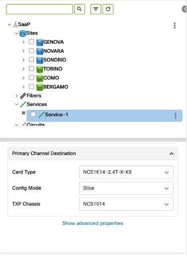
To add NCS 1014 (NCS1K14-2.4T-K9=), set these properties in the left tree panel:
Expand the service that connects to the site where NCS 1014 (NCS1K14-2.4T-K9=) is connected in the left tree panel, and then drill down to the service properties.
Under Service Properties, in Primary Channel Source, set Card Type to NCS1K14-2.4T-X-K9 and TXP Chassis to NCS1014.
Click Update.
Click Show Advance Properties, and set Src Add/drop Type and Dst Add/drop Type to Colorless/Colored.
Note
If Show Advance Properties is not displayed, check whether a service is selected in the left panel. If a service is selected, clear the selection, and then click the service again.
Click Update.
7.
To add NCS 1004 (NCS1K4-QXP-K9=), set these properties in the left tree panel:
Expand the service that connects to the site where NCS 1004 (NCS1K4-QXP-K9) is connected in the left tree panel, and then drill down to the service properties.
Under Service Properties, in Primary Channel Source, set Card Type to NCS1K4-QXP-K9 and TXP Chassis to NCS1004.
Click Update.
Click Show Advance Properties, and set Src Add/drop Type and Dst Add/drop Type to Colorless/Colored.
Click Update.
8.
Choose File, then click Save to store the project.
Alternatively, you can click Cisco Optical Network Planner Excel import/export workflow to create a network. For more details, see Import a network using an Excel sheet
The project file captures the designed topology and is ready for analysis.
You now have a fully defined Cisco Optical Network Planner network that aligns with physical requirements and can proceed to Analyze and Cisco Optical Site Manager export stages.
Share the screenshots and any Excel import artifacts with reviewers.
Analyze the network
To analyze the designed sample network and check its feasibility using the Cisco Optical Network Planner Web Interface.
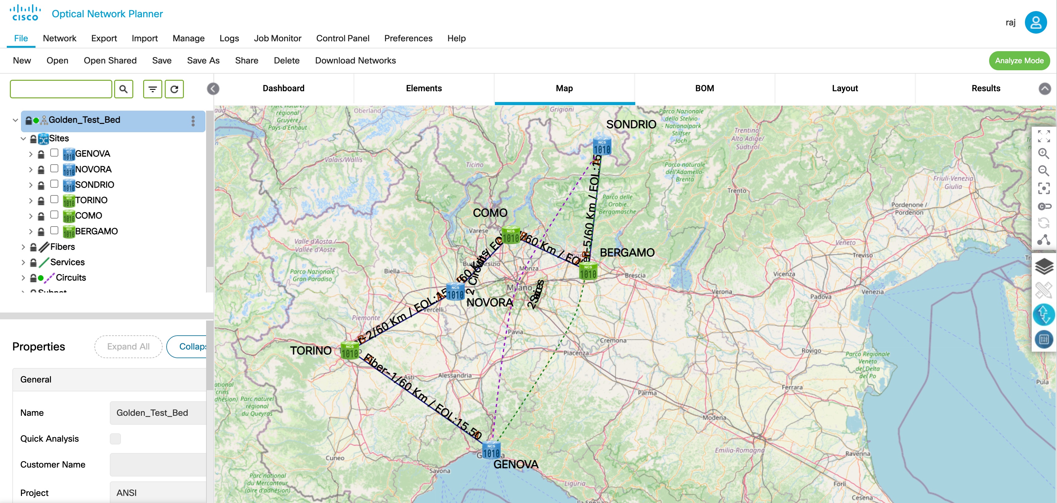
After a successful network analysis, you can validate the design by reviewing various reports available in Cisco Optical Network Planner, including Layout, NFV, BOM, and Optical Reports. These reports provide detailed information about hardware placement, interconnections, inventory, and circuit feasibility.
Figure 2. CONP Analyzed Network
Before you begin
Ensure you have access to the Cisco Optical Network Planner Web Interface and have a sample topology network created.
Follow these steps to analyze the network.
Procedure
1.
Log in to Cisco Optical Network Planner Web Interface.
2.
Click File, then click Open.
The Select Network To Open dialog box appears.
3.
Click the sample topology network that you have created, from the list of networks.
4.
Click Network, then click Analyze.
The Cisco Optical Network Planner analysis progress indicator indicates the analysis status.
Table 1. Analysis Status
If...
Then...
After successful analysis
The network goes to Analyze Mode.
If there is any failure in the analysis stage
A pop-up window appears with the message, “Analysis Failed.”
5.
Choose the Elements > Messages tab to see the list of error details in the analyzed network.
By default, it shows only the key messages when the Critical Only toggle button is enabled.
If you want to view the entire network message, disable the Critical Only toggle button.
6.
If you find an error message under the Messages tab, resolve the error and analyze the network again. Repeat this step until all errors are resolved.
7.
Validate the design by navigating to the Network View and reviewing these reports:
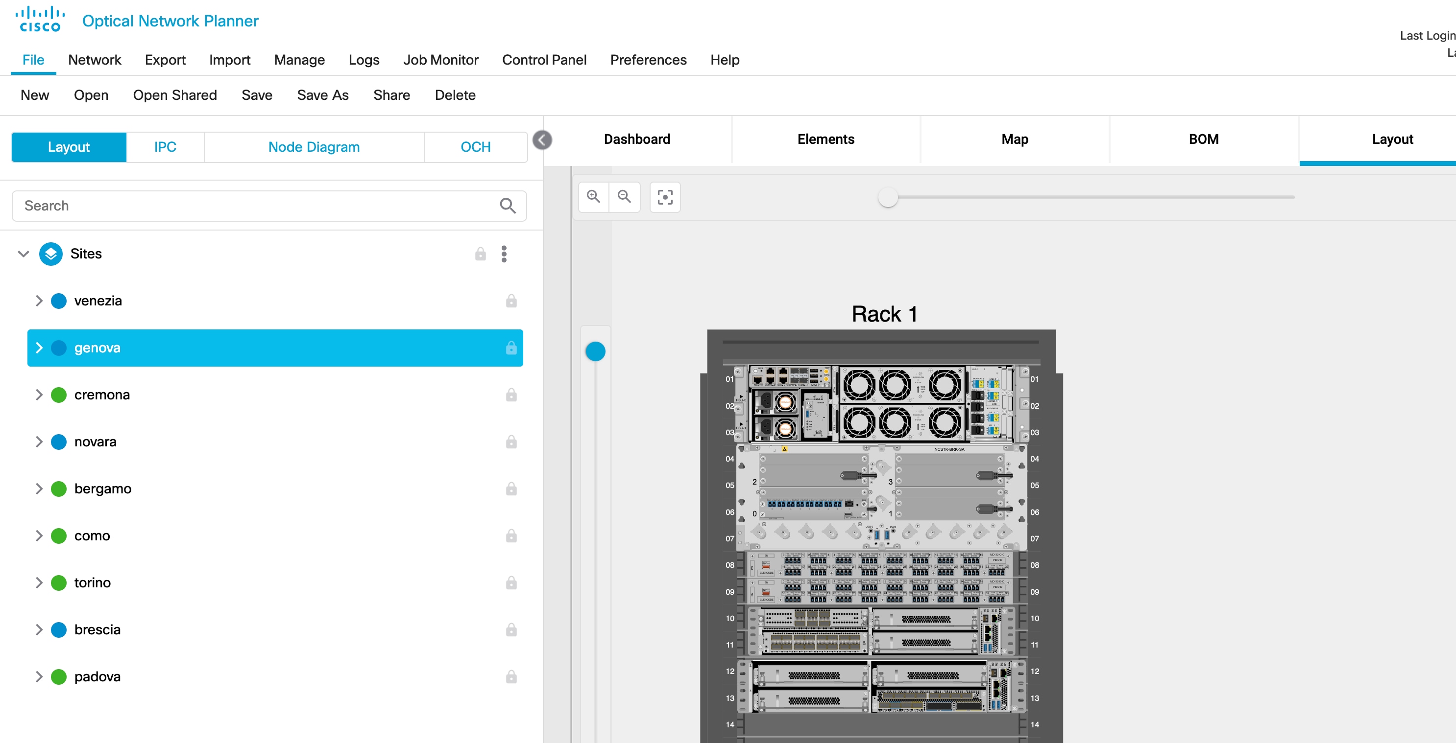
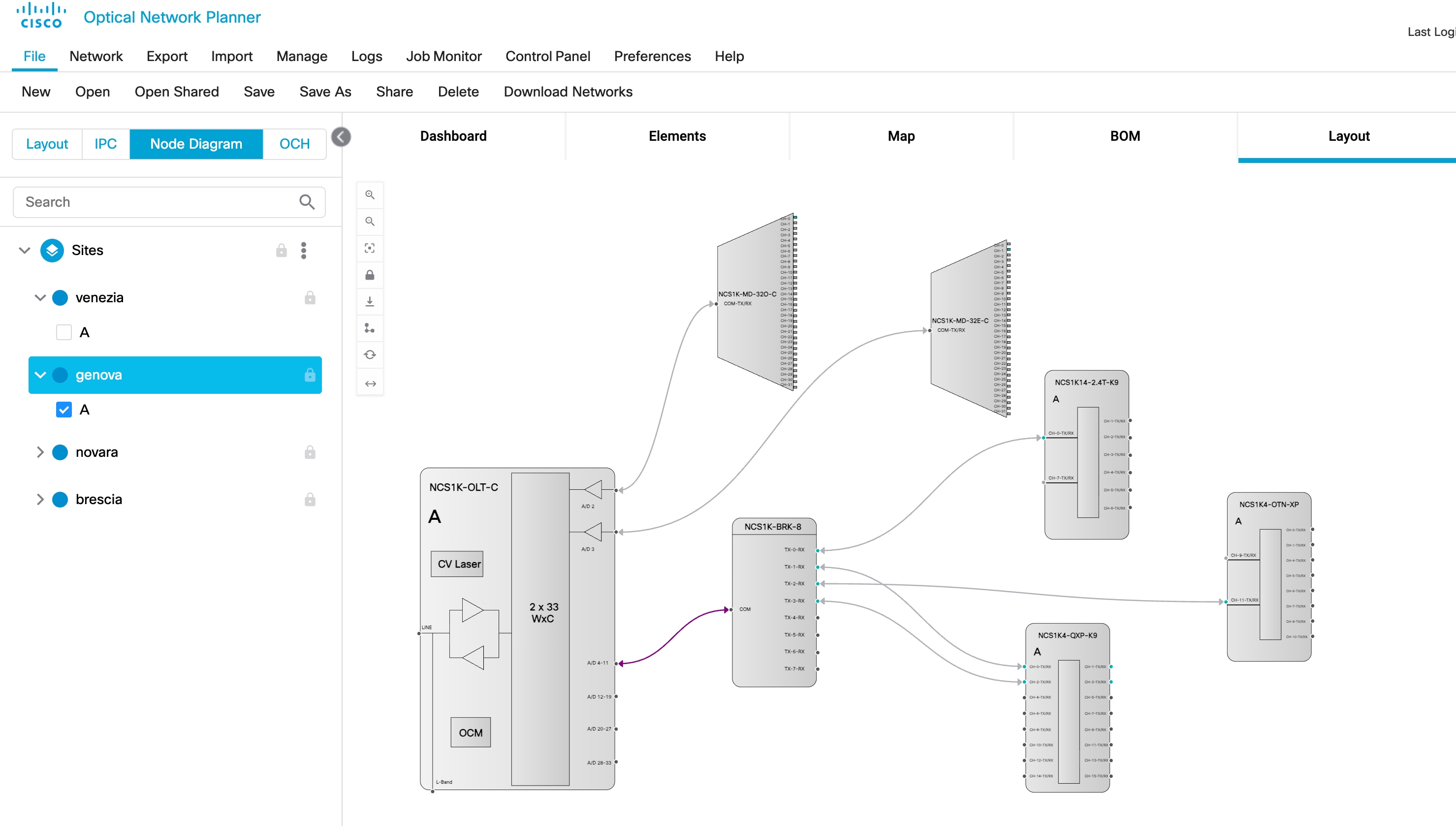
Layout Tab: View hardware placement, rack level details, and site interconnections (via Node Diagram in the left panel).
Figure 3. CONP Layout
Node Diagram: View the site interconnections.
Figure 4. CONP Node Functional View
BOM Tab: See the inventory list for each site.
Results (including Optical Reports, Installation Parameters, and Cabling Report): Validate circuit feasibility and other design parameters.
For more details about the report parameters, see Optical Report.
The network should be in an analyzed state, and you should have validated the design using the CONP reports.
Generate Cisco Optical Site Manager Netconf XML Files
Generate and prepare Cisco Optical Site Manager Netconf XML files from Cisco Optical Network Planner.
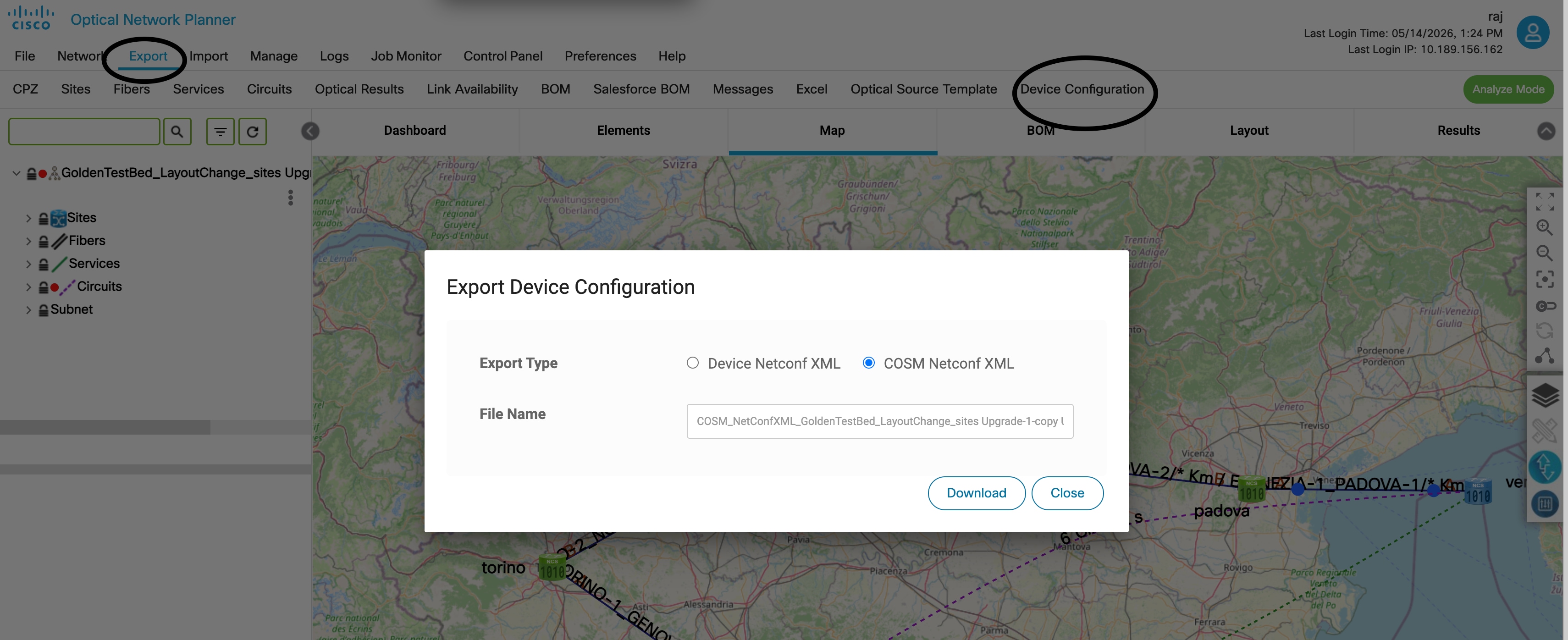
After the network has undergone analysis and validation, it is necessary to export the configuration data from Cisco Optical Network Planner in a Netconf XML format.
The exported files are packaged into a Zip archive, and each file within this archive corresponds to a specific site, identified by its unique naming convention.
Identify the individual site configuration files within the downloaded Zip file.
The Zip file contains a list of files, where each file represents a distinct site. The file name helps to identify the individual site using the format:
<NetworkName-SiteName>
.
3.
Upload each individual site file into Cisco Optical Site Manager after it is operational.
The Cisco Optical Site Manager Netconf XML files are successfully generated, extracted, and prepared for Day1 device configuration in Cisco Optical Site Manager.
What to do next
Bring up the platform and Cisco Optical Site Manager, and then configure the Day 1 device settings in Cisco Optical Site Manager by using the uploaded files.
Troubleshooting and log collection
Collect the network export and component logs required by engineering support.
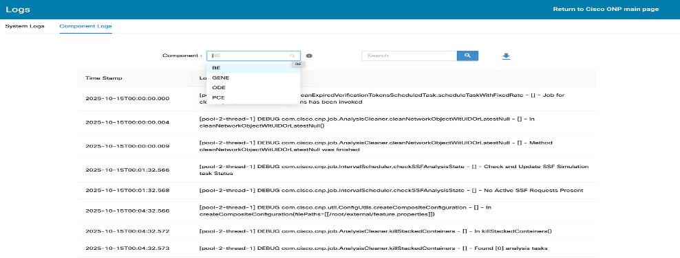
Figure 6. Cisco Optical Network Planner logs collection
To resolve any issues encountered during installation, see
Troubleshooting Guide.
Before you begin
Ensure you have administrator access to Cisco Optical Network Planner.
Verify the target network project is available in the Cisco Optical Network Planner workspace.
Follow these steps to collect troubleshooting logs for engineering support.
Procedure
1.
Open the network in Cisco Optical Network Planner, select Export, then click CPZ to export the CPZ file of the network.
2.
Export the component logs.
Click Logs, then click Component Logs.
Collect these logs: BE (CONP Backend log), GENE (NCS1010 and NCS1000 TXP Analysis Engine), ODE (NCS4k Analysis Engine), and PCE (NCS1010 Path Computation & Simulation Engine).