- Overview
- User Interface
- Plan Objects
- Traffic Demand Modeling
- Simulation
- Simulation Analysis
- Traffic Forecasting
- IGP Simulation
- MPLS Simulation
- RSVP-TE Simulation
- Segment Routing Simulation
- Layer 1 Simulation
- Quality of Service Simulation
- BGP Simulation
- Advanced Routing with External Endpoints
- VPN Simulation
- Multicast Simulation
- Metric Optimization
- LSP Optimization
- RSVP-TE Optimization
- Explicit and Tactical RSVP-TE LSP Optimization
- Segment Routing Optimization
- Capacity Planning Optimization
- L1 Circuit Path Optimization
- Changeover
- Patch Files
- Reports
- Cost Modeling
- Plot Legend for Design Layouts
Cisco WAE Design 7.0.1 User Guide
Bias-Free Language
The documentation set for this product strives to use bias-free language. For the purposes of this documentation set, bias-free is defined as language that does not imply discrimination based on age, disability, gender, racial identity, ethnic identity, sexual orientation, socioeconomic status, and intersectionality. Exceptions may be present in the documentation due to language that is hardcoded in the user interfaces of the product software, language used based on RFP documentation, or language that is used by a referenced third-party product. Learn more about how Cisco is using Inclusive Language.
- Updated:
- May 4, 2017
Chapter: BGP Simulation
BGP Simulation
This chapter describes how WAE Design models multi-AS networks and simulates basic BGP routing. WAE Design does not directly emulate BGP routing configurations, such as local prefs and MEDs. Rather, it provides a high-level modeling of typical peering policies, such as standard customer, transit, and settlement-free arrangements for service providers. This model lets you quickly and easily evaluate the effects of peering locations and basic policy variations.
Additionally, you can extend these high-level models to significantly more complex policy-based routing situations using external endpoints as demand sources and destinations. For information on demands and on external endpoints, see Traffic Demand Modeling and Advanced Routing with External Endpoints .
Internal and External AS Types
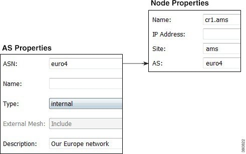
To model a multi-AS network, each node is assigned an AS, and each AS is defined as either internal or external. A typical multi-AS model in WAE Design consists of the following:
- A single internal AS representing the full topology of your network.
- Individual peering nodes of neighboring external ASes.
- Peering circuits connecting the internal AS to the nodes in the external ASes.
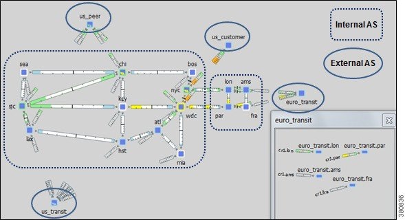
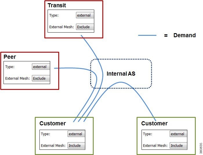
Generally, there are many external ASes in the plan file, but usually only one or a few internal ASes. All nodes in an external AS are typically placed in the same site, although you can place them in any site. Figure 14-1 shows an example model with two internal ASes and four external ASes.
AS names and their types are defined in the AS Properties dialog box and listed in the AS table. Nodes are assigned to ASes in the node Properties dialog box.
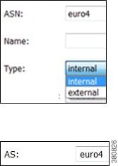
Figure 14-1 Example Multi-AS Model
Inter-AS Routing
Route Selection Between Internal ASes
Demands routed within a single AS have a specified source node and destination node where traffic originates and terminates. Demands routed between two connecting internal ASes are specified in the same manner: with a source node in the first AS and a destination node in the second.
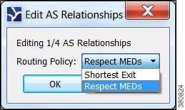
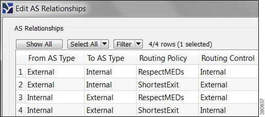
WAE Design routes within an AS, to and from the border exit point, are determined by the IGP protocols. The selection of border exit point is modeled by the Routing Policy, which is set to either Shortest Exit or Respect MEDs. This property is set in the Edit AS Relationships dialog box, which is accessed through the AS Properties dialog box.
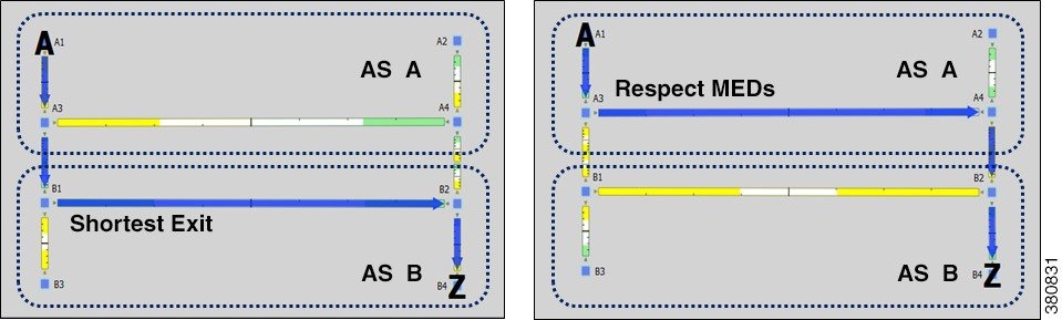
- Shortest exit—The border exit node is selected, which is closest to the source node, within the IGP of the source AS. If there is a tie, the exit node with the lowest BGP ID is used.
- Respect MEDs—The border exit node is selected, which is closest to the destination node, within the IGP of the destination AS. If there is a tie, the exit node with the lowest BGP ID is chosen.
Figure 14-2 shows these modeled as two internal ASes: AS A and AS B. The same demand (A1 to B4) is routed using each of the two different routing policies.
Figure 14-2 Route Selection Based on Routing Policy
Routes Between External and Internal ASes
Table 14-1 lists typical routing configurations that can be constructed by applying different combinations of Routing Policies for traffic in both directions between two ASes.
- In a peer relationship, routing in both directions is Shortest Exit, which means each controls its own border exit points.
- For a customer relationship, the customer determines the border exit points for traffic in both directions.
- For a transit relationship, the transit AS provides paid transit to the internal AS, so the internal AS determines all border exit points.
|
|
|
|
|---|---|---|
Like traffic routed within an AS, traffic routed between ASes is represented by demands. However, for demands from and/or to external ASes, the external AS is defined as the source or destination of the demand. Optionally, the specific node in the external AS from which the traffic enters or exits the internal AS is also specified.
Failover between nodes in the external AS can be modeled. For example, if the traffic is sourced from an external AS and if the peering circuit from which traffic is entering the internal AS under normal operation fails, the traffic can enter the internal AS from a different interface or peering node in the same external AS. In the Demands table, the sources and destinations are represented as follows.
AS{<ASN>}:if{node_name|interface_name}
Example: AS{33287}:if{cr01.newyork.ny|POS3/7/0/0}
For more detailed information on demand sources and destinations, see Traffic Demand Modeling .
The AS that controls the routing chooses which peering node to use. If the internal AS controls the routing, then because the topology of the internal AS is known, you can simulate the routing to the peering node. However, because WAE Design has limited knowledge of the external AS topology, if the external AS controls the routing, you cannot predict how traffic will be distributed among the exit points.
The AS that controls the routing is determined by the AS type, direction of the demand, and the Routing Policy property as described in Table 14-2 .
|
|
|
|
|---|---|---|
Two ASes can be in one of four different routing relationships to one another, depending on which of the two routing policies is chosen in each direction ( Table 14-3 ).
- If traffic is routed to an external AS when it has control and there is no knowledge of its topology, a set of demands is created from the source in the internal AS (or from another external AS), each with a destination set to one of the border nodes in the external AS. This way, any division of traffic between the exit points can be modeled.
- If traffic is routed to an external AS when an internal AS has control, a single demand is created from the source to the AS itself. WAE Design simulations determine the correct exit point for this single demand based on the source.
- If traffic is to be routed from an external AS when it has control, a demand is created from each node in the external AS to each node in the internal AS.
- If traffic is to be routed from an external AS when an internal AS has control, a demand is created to each node in the internal AS using the external AS as the source. The demand originates from one or multiple nodes in the external AS, depending on the topology and the metric cost to reach the destination node. For example, a single demand from an external AS to a specific node could be sourced from two different nodes in the external AS, each carrying 50% of the demand traffic.
|
|
|
|
|
|
|---|---|---|---|---|
External Meshes
An external mesh consists of two or more external ASes with a Type property of External. An internal AS typically restricts advertisement of BGP routes for some external ASes to other external ASes. For example, destinations reachable through the transit network would not be advertised to a peer, or vice versa. In WAE Design, these restrictions are represented by the absence of demands between the two external ASes.
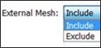
Each AS has a property called External Mesh, which WAE Design uses when inserting demand meshes into a plan. Demands are created for external ASes only if one or both ASes have External Mesh set to Include. If both ASes are set to Exclude, no demands are created for the external AS. For example, in Figure 14-3 the peer and transit ASes are both set to Exclude, so no demands are created between those ASes. All other external AS demands are included in the demand mesh. Table 14-4 shows the External Mesh settings for common AS relationships.
The External Mesh property is set in the AS Properties dialog box.
|
|
|
|
|---|---|---|
For internal ASes, the External Mesh property is ignored. More complex route advertisement policies cannot be represented by these simple External Mesh settings. In this case, demand mesh creation must be performed in several steps, possibly using a script and the dmd_mesh_creator CLI tool.
Figure 14-3 External Mesh Control
BGP Simulations
As with all WAE Design simulations, AS routing uses demands. An IP simulation for a particular failure scenario and traffic level performs these steps.
Step 1![]() Demands are routed using the established LSPs (if applicable) and using the specified BGP protocols given the specified failure scenarios.
Demands are routed using the established LSPs (if applicable) and using the specified BGP protocols given the specified failure scenarios.
Step 2![]() Interface utilizations are calculated from the demand traffic using the specified traffic level.
Interface utilizations are calculated from the demand traffic using the specified traffic level.
WAE Design allows routes to be calculated between selected nodes even if no demands are present. In this case, only the first step applies.
BGP demands do not failover between external ASes. That is, all traffic to or from an external AS behaves the same under peering failures to an external AS. You can change this default behavior using external endpoints to simulate specific external AS nodes where traffic goes in and out of the network, as well as set priorities so that if one traffic source or destination goes down, the traffic can still be sourced from or delivered to another external AS node.
BGP Routing Details
BGP Multihop
WAE automatically constructs BGP pseudonodes where necessary when BGP multihops are detected.
WAE Design models the nodes in external ASes that are directly connected, for example through eBGP, to nodes in internal ASes. One exception is that you can model BGP multihops by setting the node Type property to psn (pseudonode), such as might occur at a peering exchange. This pseudonode can represent the switch that connects a number of external AS nodes to the same internal AS node. In this instance, multiple external AS nodes are connected by circuits to a BGP psn node, and this node is connected to a node in the internal AS.

Note![]() In all cases, eBGP multipaths across parallel border circuits is assumed.
In all cases, eBGP multipaths across parallel border circuits is assumed.
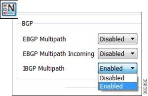
BGP Load Balancing
BGP load balancing to an external AS uses eBGP multipaths or eBGP multihops. WAE Design models these two eBGP load balancing designs in the same manner, though in the GUI they are identified only as multipaths. BGP multipath options are disabled by default.
To set BGP multipath options globally, follow these steps:
Step 1![]() Choose Edit > Network Options or click the Network Options icon in the Visualization toolbar.
Choose Edit > Network Options or click the Network Options icon in the Visualization toolbar.
Step 2![]() Click the Protocols tab.
Click the Protocols tab.
Step 3![]() For each BGP multipath option that you want enabled, choose Enabled, and then click OK.
For each BGP multipath option that you want enabled, choose Enabled, and then click OK.
- EBGP Multipath—Turns on eBGP multipath within the internal ASes. Demand routings through the internal AS to an external AS are divided among external routes with equal-cost BGP exit routes.
- EBGP Multipath Incoming—Turns on eBGP multipath in all external ASes. Demand routings from external ASes to an internal AS are divided among external routes with equal-cost BGP exit routes.
- IBGP Multipath—Turns on iBGP multipath within the internal ASes. Demand routes through an internal AS to an external AS are divided among internal paths to equal-cost BGP exit routes.
BGP Next Hop
In networks, there are two common configurations for the BGP next-hop IGP metric used in the path selection. One is to set the next-hop self on the iBGP peers (next-hop self = on). The other is to configure IGP metrics on eBGP interfaces, and to inject the interface prefix into the IGP database by setting the interface to be a passive IGP interface (next-hop self = off).
WAE Design does not have an explicit next-hop self setting so it simulates paths as if next-hop self is off. That is, the IGP metric of the egress peering interface is included in the IGP distance to the peering router and is used in the iBGP path selection. However, next-hop self to an external AS can effectively be simulated by setting the metrics on all egress interfaces to that external AS to 0. (You can set the IGP metric in either the Interfaces Properties or Circuit Properties dialog box accessed through the context menu.)
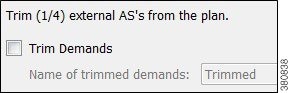
Trimming ASes
A plan file that uses BGP discovery typically has more external ASes in the plot than you are interested in viewing or simulating. Some ASes might have very low traffic levels and others might have only one circuit connecting into the internal AS. You can trim these unwanted ASes to simplify the network. Trimming removes the AS from the plan file, but retains the traffic in and out of the AS for simulation. That is, its interface traffic is still included in the total traffic of connected nodes.
Typically, plan files are trimmed before demands are created. However, you can optionally trim demands in a plan file. If any demand is sourced from a trimmed external AS, the demand source is moved to the first hop on the demand path in the remaining network. Likewise, if a demand has a destination that is a trimmed external AS, the demand destination is moved to the last hop in the remaining network. If two or more demands in the same service class are trimmed so that their resulting source and destination nodes are equal, these demands are aggregated into one demand with their traffic summed. Demands split by ECMPs are converted into multiple demands, each with traffic divided proportionally to the split ECMP.
Note that multicast demands are removed, and cannot be trimmed.
Step 1![]() Select one or more ASes to trim from the AS table.
Select one or more ASes to trim from the AS table.
For example, sort the ASes by traffic level and then select all ASes that are below the level of interest. Alternatively, filter the table for traffic using the less than operator (<) and the traffic level, and then select the filtered ASes.
Step 2![]() Right-click one of the selected ASes and choose Trim.
Right-click one of the selected ASes and choose Trim.
Step 3![]() (Optional) Select the option to trim demands.
(Optional) Select the option to trim demands.
By default, the moved demands are named “Trimmed,” though you can enter a different name.
Creating ASes
Follow these steps to create an empty AS. After creating the AS, you still need to associate nodes with it and create the relationship between this AS and others. See Associating Nodes with an AS and Editing AS Routing Policies.
Step 1![]() Choose Insert > AS, or right-click in the empty plot and choose New > AS.
Choose Insert > AS, or right-click in the empty plot and choose New > AS.
Step 2![]() Configure the AS properties:
Configure the AS properties:
- ASN—AS number, which is a text string that can be a number or name.
- Name—AS name.
- Type—Internal ASes have a full topology. External ASes have a collapsed topology with just border nodes and a virtual node.
- External Mesh—When creating a demand mesh, this option tells WAE Design whether to create external meshes. When one or both ASes are set to Include, WAE Design creates a mesh between the external ASes (default). If both are set to Exclude, no demands are created.
- Description—A text description of the AS.
Step 3![]() To change the routing policy, click Edit AS Relationships. (The default is Respect MEDs.) For information on how these options affect simulation, see Route Selection Between Internal ASes.
To change the routing policy, click Edit AS Relationships. (The default is Respect MEDs.) For information on how these options affect simulation, see Route Selection Between Internal ASes.
Step 4![]() Click OK to create an empty AS.
Click OK to create an empty AS.
Associating Nodes with an AS
Step 1![]() Choose one or more nodes, and double-click any one of them to open the node Properties dialog box.
Choose one or more nodes, and double-click any one of them to open the node Properties dialog box.
Step 2![]() In the AS drop-down list, choose the AS to which you want to assign the nodes. Then click OK.
In the AS drop-down list, choose the AS to which you want to assign the nodes. Then click OK.
Editing AS Routing Policies
To create AS relationships, set the routing policy.
Step 1![]() Choose an AS from the AS table.
Choose an AS from the AS table.
Step 2![]() Follow one of these methods to open the Edit AS Relationships dialog box:
Follow one of these methods to open the Edit AS Relationships dialog box:
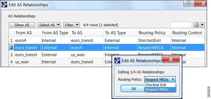
Step 3![]() Choose the AS pair that you want to configure. There is a separate line for each direction in the relationship so you can configure them independently.
Choose the AS pair that you want to configure. There is a separate line for each direction in the relationship so you can configure them independently.
Step 4![]() Click Edit, set the Routing Policy to Respected MEDs (default) or Shortest Exit, and click OK.
Click Edit, set the Routing Policy to Respected MEDs (default) or Shortest Exit, and click OK.
Assigning Names to ASNs
WAE Design can assign names to ASNs by looking them up in the $CARIDEN_HOME/etc/ASNs.txt file. This file contains a list of all assigned ASNs with their names and descriptions.
Step 1![]() Choose one or more ASes from the AS table. If no ASes are selected, names are assigned to all ASes in the plan.
Choose one or more ASes from the AS table. If no ASes are selected, names are assigned to all ASes in the plan.
Step 2![]() Choose Initializers > Assign Names to ASNs, or right-click an AS and choose Assign Names to ASNs.
Choose Initializers > Assign Names to ASNs, or right-click an AS and choose Assign Names to ASNs.
Step 3![]() To assign names only if the ASN does not have one, check Only those with blank Name fields.
To assign names only if the ASN does not have one, check Only those with blank Name fields.
 Feedback