- Overview
- User Interface
- Plan Objects
- Traffic Demand Modeling
- Simulation
- Simulation Analysis
- Traffic Forecasting
- IGP Simulation
- MPLS Simulation
- RSVP-TE Simulation
- Segment Routing Simulation
- Layer 1 Simulation
- Quality of Service Simulation
- BGP Simulation
- Advanced Routing with External Endpoints
- VPN Simulation
- Multicast Simulation
- Metric Optimization
- LSP Optimization
- RSVP-TE Optimization
- Explicit and Tactical RSVP-TE LSP Optimization
- Segment Routing Optimization
- Capacity Planning Optimization
- L1 Circuit Path Optimization
- Changeover
- Patch Files
- Reports
- Cost Modeling
- Plot Legend for Design Layouts
Cisco WAE Design 7.0.1 User Guide
Bias-Free Language
The documentation set for this product strives to use bias-free language. For the purposes of this documentation set, bias-free is defined as language that does not imply discrimination based on age, disability, gender, racial identity, ethnic identity, sexual orientation, socioeconomic status, and intersectionality. Exceptions may be present in the documentation due to language that is hardcoded in the user interfaces of the product software, language used based on RFP documentation, or language that is used by a referenced third-party product. Learn more about how Cisco is using Inclusive Language.
- Updated:
- May 4, 2017
Chapter: RSVP-TE Optimization
RSVP-TE Optimization
The RSVP-TE Optimization tool (Tools > RSVP LSP Optimization > RSVP-TE Opt) creates explicitly routed LSP paths to optimize route properties such as distance, TE metrics, utilization, and disjointness. The routing decisions are centralized within the tool, in contrast to traditional RSVP-TE routing, in which routing decisions are distributed across the head-end routers in the network. Although it has fewer parameters, this tool is faster and has a more predictable run-time than the Explicit LSP Optimization tool and is the recommended method for explicit RSVP-TE LSP path optimization.
The primary optimization goal is to minimize path distance (which can be based on interface TE metrics, delay, or user-defined value), while not exceeding a bandwidth bound defined for each interface so as to avoid congestion. Unlike RSVP-TE, LSPs are routed even if they cannot avoid exceeding bandwidth bounds for certain interfaces, though these bound violations are minimized. Additionally, you can use this tool for reoptimizing and reconfiguring RSVP-TE LSPs after events, such as network failures and subsequent route reconvergence.
You can specify different treatment for different LSPs: whether the LSPs should be rerouted to shorten the path distance, only as necessary to reduce congestion, or not optimized at all. These three LSP groups are called Opt, Fit, and Fix. Using these input parameters allows for a variety of use cases, such as:
- Global optimization—Minimize the path length of all LSPs subject to specified interface bandwidth constraints.
- New LSP optimization—Minimize the path length of newly created LSPs without exceeding bandwidth bounds specified for the interfaces. Existing LSPs are kept on their current paths, being moved only if necessary to prevent new LSPs from violating bandwidth bound constraints.
- Tactical congestion mitigation—Change the routing of as few LSPs as possible to bring bandwidth on all interfaces below the specified bandwidth bound.
Upon completion, WAE Design generates a new plan file with a suffix, which by default is RSVPTEOpt. This suffix is configurable in the “New plan for result” field. As such, the tool is beneficial for offline planning and configuration of an explicitly routed RSVP-TE network. It is also useful for providing routing decisions for a centralized, reactive network control application, such as can be implemented on the WAE platform.
This optimized plan file opens showing the LSPs table filtered to the rerouted LSPs. Saving this plan file then simplifies the process of identifying which LSPs to reconfigure in the network.
Optimization Input
The RSVP-TE Optimization tool uses the LSP and interface input properties listed in Table 20-1 to execute its optimization calculations. These properties, which are specified in user columns in the LSPs and Interfaces tables, can be created in one of two ways:
- Use the tool to automatically create (initialize) the properties if they do not exist. The selections made in the Specify LSP Groups, LSP Parameters, and Interface Parameters areas populate the input properties.
Example: If you choose LSPs to optimize, to fit, and to fix, the tool creates the RSVPTEOpt::Group column in the LSPs table and sets this property to the appropriate values for each LSP (Opt, Fit, Fix). If the property already exists, it is updated with the new value if it has changed.
Example: If you select to set the interface bandwidth bound based on the Resv BW property, the tool creates the RSVPTEOpt::BWBound column in the Interfaces table and for each interface, copies the Resv BW value to it. If the property already exists, it is updated with the new bandwidth bound value if it has changed.
- Before running the tool, manually create the input properties as user columns in the LSPs and Interfaces tables. When running the tool, you must then select the “Use Existing RSVPTEOpt::<property_name>” option. This is useful if you want to configure specific values rather than using existing properties and values. For information on creating user-defined columns, see User Interface or the Cisco WAE Design Integration and Development Guide.

Note![]() Because the resulting plan file can potentially reset properties that can be used as input to optimizations, it is a best practice to run the optimization only on plan files or LSPs that have not yet been optimized. For example, by default WAE Design resets the LSP Setup BW property to 0 after optimizing LSPs, and this same property could be used as input to other optimizations.
Because the resulting plan file can potentially reset properties that can be used as input to optimizations, it is a best practice to run the optimization only on plan files or LSPs that have not yet been optimized. For example, by default WAE Design resets the LSP Setup BW property to 0 after optimizing LSPs, and this same property could be used as input to other optimizations.
Selecting LSP Groups
To determine how and whether LSPs are optimized, select them from the Specify LSP Groups area. If an LSP is in multiple groups, the first group in which it resides is how the LSP is treated.
- Opt—Explicitly route or reroute these LSPs to minimize their path length, while respecting the bandwidth bounds specified for the interfaces. The RSVP-TE Opt tool changes the LSP path as much as needed to find the optimal route. First, it tries to set the LSP to its shortest path, which is defined by the interface Metric parameter. The LSP is moved away from the shortest path only if needed due to congestion.
Setting all LSPs to this option is useful when trying to achieve global optimization on all LSPs.
This option is useful when attempting tactical congestion mitigation, where it is desirable to move as few LSPs as possible to remove existing congestion.
A combination of Opt and Fit or a combination of Opt and Fix is useful for targeting the optimization of new LSPs.
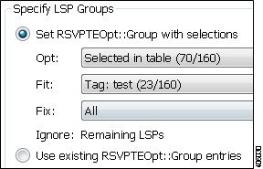
LSPs that are not selected are ignored, and as such, maintain their original configuration and are not considered in the optimization calculations. This can be useful if you have network regions that do not interfere with optimizations. Note, though, that if measured interface traffic is used in the optimizations, traffic contributions from the ignored LSPs to this measured traffic might affect the results.
Because you can set each of the “Set RSVPTEOpt::Group” selections to None, All, only selected, or tagged LSPs, you can section off specific LSPs for one optimization treatment or another.
Example: Tag new LSPs and set them to be optimized (Opt LSPs). Select and set existing LSPs to Fit LSPs to optimize their paths only as necessary to accommodate bandwidth bound constraints.
Setting Optimization Parameters
Optimization calculations are based on two sets of parameters that define how much bandwidth the LSPs require, how much bandwidth the interfaces have available for these LSPs, and which metric to use for shortest path. See Table 20-1 for selection options.
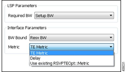
- LSP Required BW—Specify how to determine the bandwidth required for the primary LSP paths.
- Interface parameters:
–![]() BW Bound—Specify how much bandwidth the interfaces have available to carry LSPs. WAE Design tries to route LSPs without surpassing this bound, but exceeds it if necessary.
BW Bound—Specify how much bandwidth the interfaces have available to carry LSPs. WAE Design tries to route LSPs without surpassing this bound, but exceeds it if necessary.
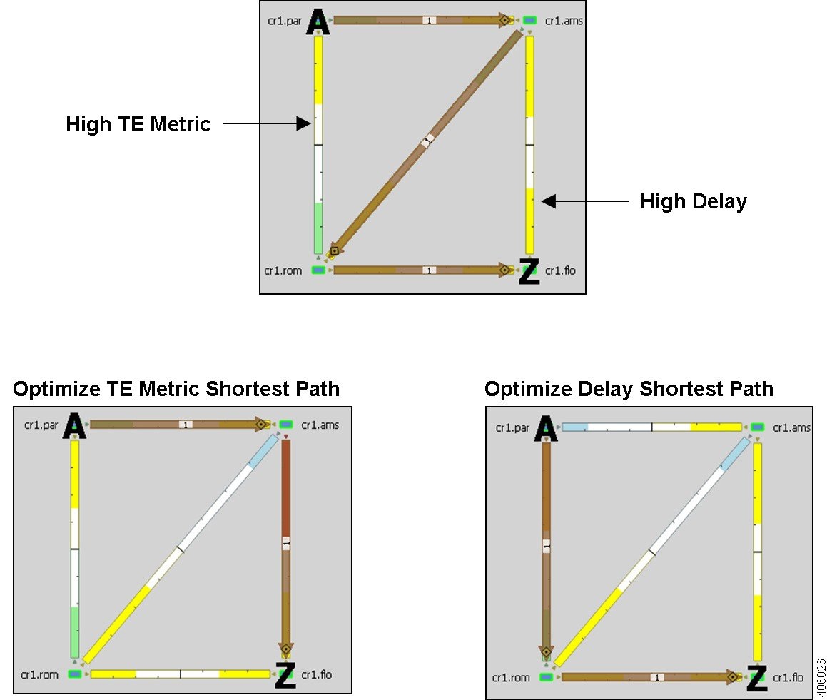
–![]() Metric—Specify which metric to use for shortest path calculations. Figure 20-1 shows a sample LSP path that is optimized once based on the TE Metric and once based on the Delay.
Metric—Specify which metric to use for shortest path calculations. Figure 20-1 shows a sample LSP path that is optimized once based on the TE Metric and once based on the Delay.
Figure 20-1 Example Shortest Path Optimization
Setting Disjoint Groups
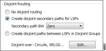
In the Advanced tab, you can create disjoint paths or use existing disjoint paths as follows. Note that two LSP paths are disjoint if they do not route over common objects. These objects are configurable and can be circuits, nodes, sites, SRLGs, or L1 links.
- No disjoint routing—Do not create disjoint secondary paths and do not enforce any disjointness on primary paths.
- Create disjoint secondary paths for LSPs—Create secondary LSP paths that are disjoint from the primary LSP paths.
Additionally, specify whether to include secondary paths in the optimization. If set to Zero, their bandwidths are set to 0 and are not included. Otherwise, their required bandwidths are set to be the same as the primary paths, and they are included in the optimization.
- Create disjoint paths between LSPs in Disjoint Groups—Create disjoint paths between LSPs that are in disjoint groups.
Setting Post-Optimization Parameters
The Post Optimization options identify how to reset the Setup BW for modified LSPs:
Optimization Output
Properties Created
In addition to creating the input parameters, as described in Optimization Input, the tool generates the properties listed in Table 20-2 . These properties provide further insight into the optimizations.
|
|
|
|
|---|---|---|
Sum of the bandwidth required for all LSPs routed on the interface. |
||
Identifies whether the bandwidth bound of the interface was exceeded. |
Optimized LSPs Reconfigured
The optimized LSPs are reconfigured with the following parameters:
- Metric Type—Autoroute
- Metric and Hop Limit—na
- Setup BW—0, the same value as the resulting RSVPTEOpt::BWReq, or unchanged, depending on how you configured the Post Optimization option in the Advanced tab
- Primary paths Standby—T (true)
- Status—Active
- FRR Enabled—T (true)
- LSP entry in the Actual Paths table is removed
Reports
WAE Design writes a report containing the results of the optimization. To access this information, choose Window > Reports.
The report summarizes the results of the optimization, such as how many LSPs there are total compared to how many were optimized, as well as how they were optimized. It also summarizes how disjoint priorities were handled and the number of paths that exceed the interface’s bandwidth bound.
Examples
Optimizing New LSPs Example
Figure 20-2 shows three LSPs: LSP_A is configured with 4000 Mbps of Setup BW, LSP_B with 5000 Mbps of Setup BW, and LSP_C, which represents a newly added LSP, with 6000 Mbps of Setup BW. Each interface has a Resv BW value of 10,000 Mbps. Without optimization, this newly added LSP_C is using three hops to reach cr1.bos because this is the only path with sufficient bandwidth.
Figure 20-2 Non-Optimized LSP Routes
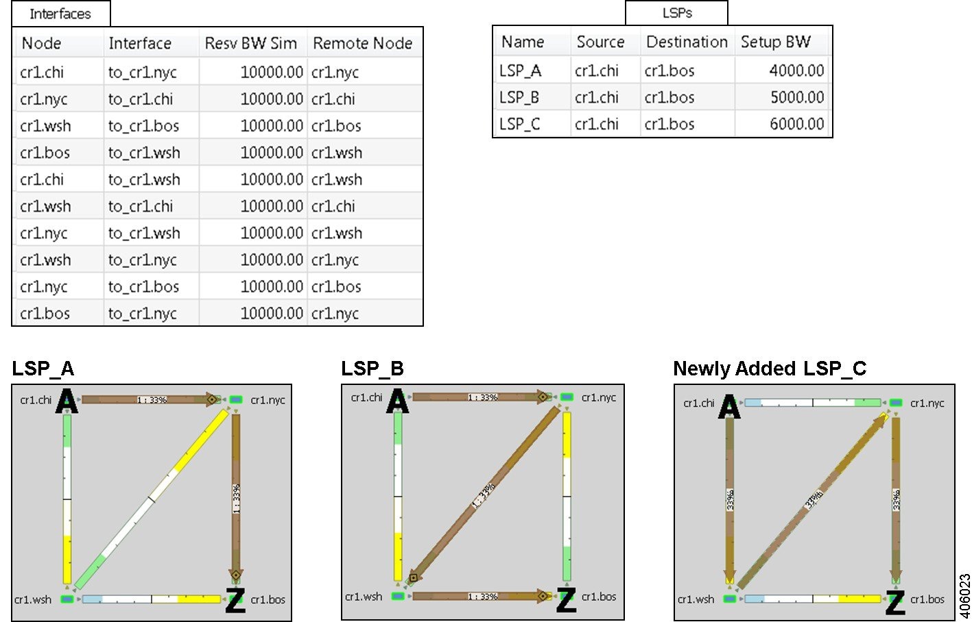
Figure 20-3 shows the results of prioritizing the optimization of the new LSP by setting it to Opt, and setting the other two LSPs to route “as is” by setting them to the Fix LSP group. The LSP Required BW parameter is Setup BW, and the interface BW Bound is Resv BW. While a primary path with explicit hops is created for LSP_C, all LSPs remain on the same route. This demonstrates that LSP_C cannot go on a two-hop path without exceeding bandwidth and it cannot alter this behavior by shifting the other two LSPs around because they are set to Fix. The interface bandwidth bound, however, is not exceeded, which is shown in the RSVPTEOpt::BWBoundExceeded column in the Interfaces table. The LSPs table shows that only LSP_C was updated in the RSVPTEOpt::Action column, and that neither LSP_B, nor LSP_C are on their shortest path. Notice also in the LSPs table that the Setup BW values are reset to 0, which is the default behavior, and that the RSVPTEOpt::Group shows how each LSP was considered during the optimization (Fix or Opt).
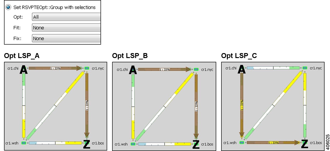
Figure 20-4 shows the results of an alternative optimization where all three LSPs are set to Opt. The resulting plan file shows both LSP_B and LSP_C were optimized to route on shortest paths without exceeding bandwidth bounds.
Figure 20-3 Example: No Optimization Improvements When Setting New LSP_C to Opt and All Other LSPs to Fix
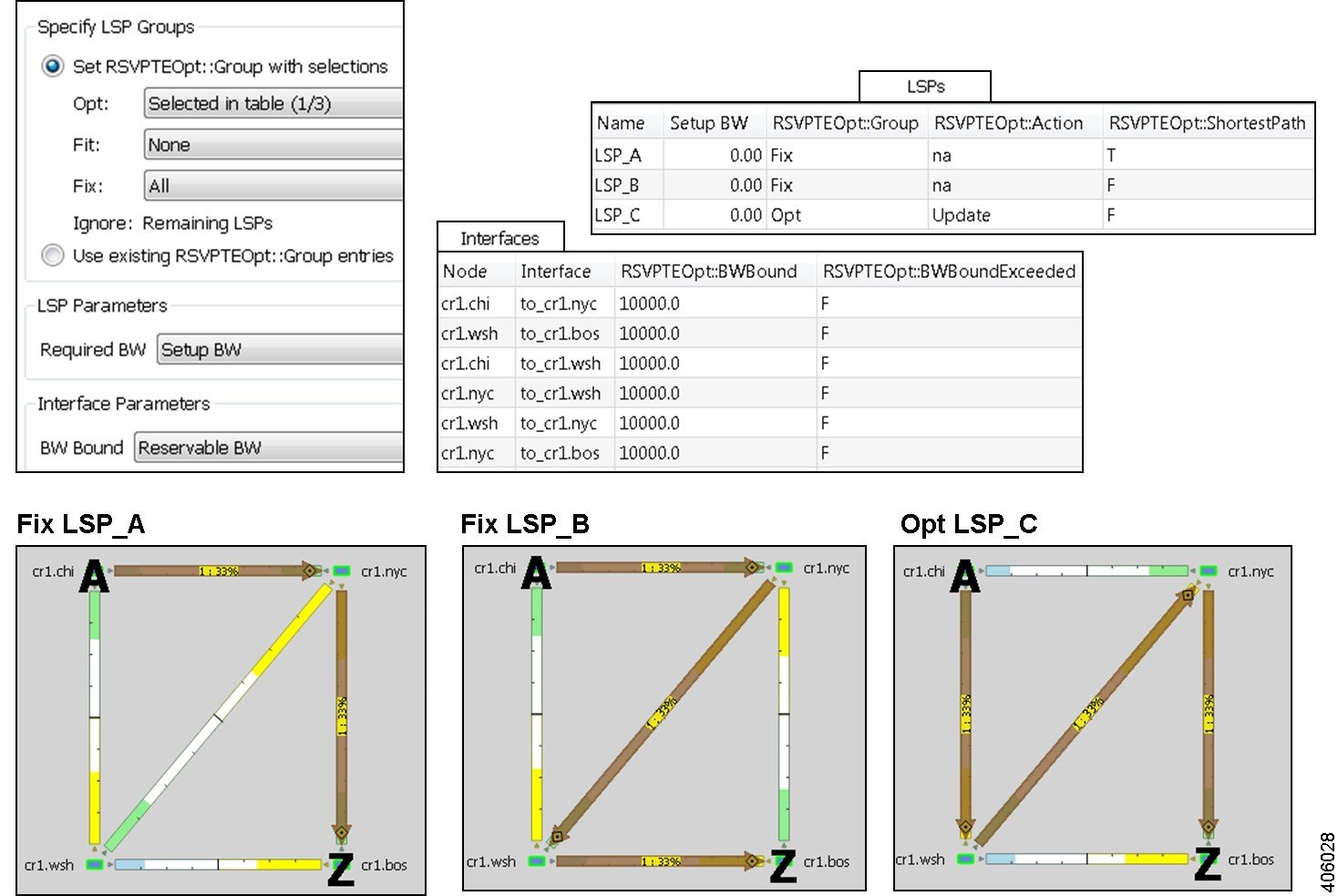
Figure 20-4 Example: Improved Global Optimization When Setting All LSPs to Opt
Tactical Mitigation Example
Figure 20-5 shows three non-optimized LSPs: LSP_A and LSP_B have 4000 Mbps and 5000 Mbps of Setup BW, respectively. They route the same as in Figure 20-2. LSP_C has 12,000 Mbps of Setup BW, leaving it unable to route because all interfaces have a Resv BW of 10,000 Mbps.
Figure 20-5 Unroutable LSP Due to Insufficient Bandwidth
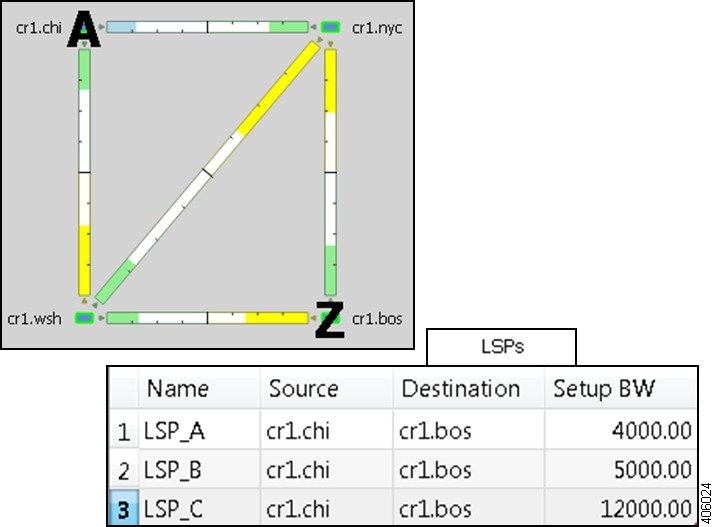
Figure 20-6 shows an optimization run to set this high-Setup BW LSP_C to Opt and keep the other LSPs set to Fix. This results in congestion and leaves three interfaces exceeding their bandwidth bound.
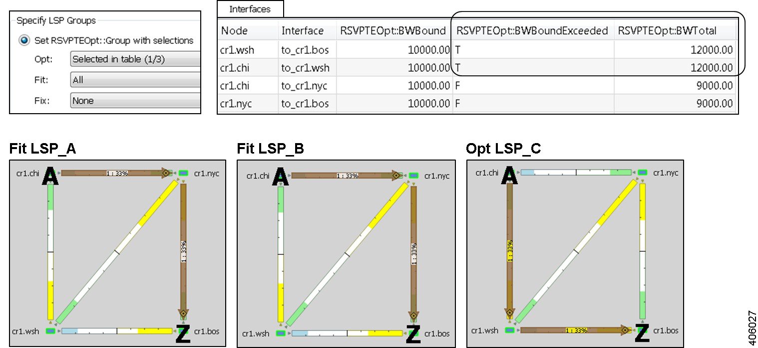
An alternative is shown in Figure 20-7, where congestion is reduced by running the optimization to set LSP_C to Opt, while setting the other to LSPs to Fit. This lets WAE Design adjust the routes of the other LSPs to achieve the best optimization possible (lowest shortest-path metric with the least congestion). While both LSP_B and LSP_C route on two hops now, two interfaces still exceed their bandwidth bound, though the amount of congestion is significantly less. Note that the same result would be achieved if all three LSPs had been set to Opt.
Figure 20-6 Example: Congestion Occurs When Settings LSPs to Fix
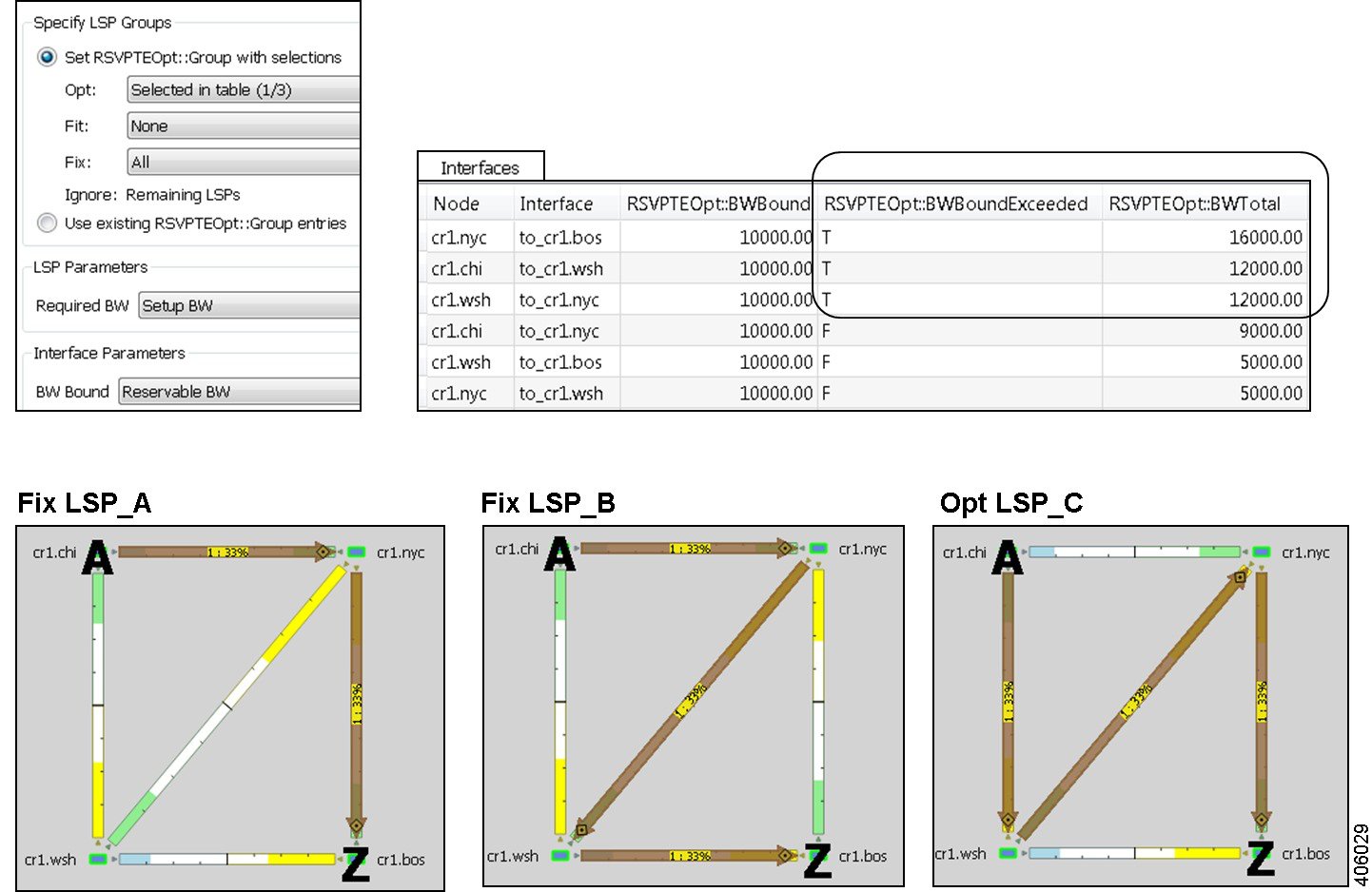
Figure 20-7 Example: Tactical Congestion Mitigation Using Fit LSPs
Workflow
Step 1![]() If this is the first time using the tool and if you want to use your own preconfigured RSVPTEOpt properties, you must manually edit the LSPs and Interfaces tables to create them.
If this is the first time using the tool and if you want to use your own preconfigured RSVPTEOpt properties, you must manually edit the LSPs and Interfaces tables to create them.
- LSP RSVPTEOpt::Group—Place LSPs into the Opt, Fit, or Fix groups. Any remaining LSPs are placed in the Ignore group.
- LSP RSVPTEOpt::RequiredBW—Define an exact amount for the sum total of LSP bandwidth that is using the interface.
- Interface RSVPTEOpt::BWBound—Define an exact amount of bandwidth that the interface can hold.
- Interface RSVPTEOpt::Metric—Define an exact amount to use in shortest path calculations.
Step 2![]() If creating disjoint paths between LSPs in the same disjoint group, the LSPs must first be added to the disjoint groups in the LSP Properties dialog box. Here, you can also assign priorities to LSPs within these groups. Higher priority LSPs are assigned shorter routes based on the metric being used for shortest path calculations. The higher the number, the lower the priority.
If creating disjoint paths between LSPs in the same disjoint group, the LSPs must first be added to the disjoint groups in the LSP Properties dialog box. Here, you can also assign priorities to LSPs within these groups. Higher priority LSPs are assigned shorter routes based on the metric being used for shortest path calculations. The higher the number, the lower the priority.

Step 3![]() If using tagged LSPs, create those tags. For information on how to create tags, see Plan Objects .
If using tagged LSPs, create those tags. For information on how to create tags, see Plan Objects .
Step 4![]() If running the optimization based on selections, select those LSPs.
If running the optimization based on selections, select those LSPs.
Step 5![]() Choose Tools > RSVP LSP Optimization > RSVP-TE Opt.
Choose Tools > RSVP LSP Optimization > RSVP-TE Opt.
Step 6![]() In the Specify LSP Groups area, make selections for optimizing LSPs based on Opt, Fit, or Fix LSP groups, or based on those defined in the RSVPTEOpt::Group property.
In the Specify LSP Groups area, make selections for optimizing LSPs based on Opt, Fit, or Fix LSP groups, or based on those defined in the RSVPTEOpt::Group property.
Step 7![]() In the Required BW field, set bandwidth requirements for the primary LSP paths.
In the Required BW field, set bandwidth requirements for the primary LSP paths.
Step 8![]() In the BW Bound field, set how much bandwidth the interfaces can carry.
In the BW Bound field, set how much bandwidth the interfaces can carry.
Step 9![]() In the Metric field, specify on which property to base the shortest path.
In the Metric field, specify on which property to base the shortest path.
Step 10![]() (Optional) Specify the name of the resulting plan file.
(Optional) Specify the name of the resulting plan file.
Step 11![]() Click the Advanced tab.
Click the Advanced tab.
Step 12![]() Identify whether to create disjoint LSP paths and if so, how you want them defined.
Identify whether to create disjoint LSP paths and if so, how you want them defined.
Step 13![]() Specify whether to reset the LSP bandwidth after the optimization, and if so, how so.
Specify whether to reset the LSP bandwidth after the optimization, and if so, how so.
 Feedback