- Overview of Prime Network GUI clients
- Setting Up the Prime Network Clients
- Setting Up Change and Configuration Management
- Setting Up Vision Client Maps
- Setting Up Native Reports
- Setting Up Fault Management and the Events Client Default Settings
- Viewing Devices, Links, and Services in Maps
- Drilling Down into an NE’s Physical and Logical Inventories and Changing Basic NE Properties
- Manage Device Configurations and Software Images
- How Prime Network Handles Incoming Events
- Managing Tickets with the Vision Client
- Viewing All Event Types in Prime Network
- Cisco Path Tracer
- Managing IP Address Pools
- Monitoring AAA Configurations
- Managing DWDM Networks
- Managing MPLS Networks
- Managing Carrier Ethernet Configurations
- Managing Ethernet Networks Using Operations, Administration, and Maintenance Tools
- Monitoring Carrier Grade NAT Configurations
- Monitoring Quality of Service
- Managing IP Service Level Agreement (IP SLA) Configurations
- Monitoring IP and MPLS Multicast Configurations
- Managing Session Border Controllers
- Monitoring BNG Configurations
- Managing Mobile Transport Over Pseudowire (MToP) Networks
- Managing Mobile Networks
- Managing Data Center Networks
- Monitoring Cable Technologies
- Monitoring ADSL2+ and VDSL2 Technologies
- Monitoring Quantum Virtualized Packet Core
- VSS Redundancy System
- Icon Reference
- Permissions Required to Perform Tasks Using the Prime Network Clients
- Correlation Examples
- Managing certificates
Icon Reference
The following topics identify the buttons, icons, and badges used in the Vision client and the Events client:
Icons
Icons are categorized into these four classes:
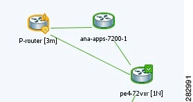
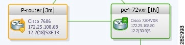
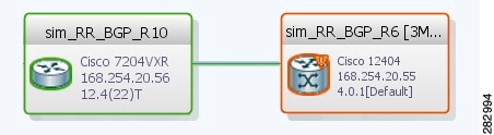
NE Type Icons
When an NE icon changes color, that means it has a ticket, and the ticket has the severity indicated by the color (see Severity Icons and Colors for Events, Tickets, and NEs). Depending on the icon size, the following information may also be displayed:
- Element model
- IP address
- Software version
- Inventory button
- Filter Tickets button
- Attach Business Ta g button
|
|
|
|---|---|

|
|

|
|

|
|

|
|

|
|

|
|

|
|

|
|

|
|

|
|

|
|

|
|

|
|

|
|

|
|

|
|

|
|

|
|

|
|

|
|

|
|

|
Lock, or security violation; viewable by a user with a higher permission level |

|
Missing icon, displayed in either of the following situations: |

|
|

|
|

|
|

|
|

|
|

|
|

|
|

|
|

|
|

|
|

|
|

|
|

|
Business Element Icons)
|
|
|
|
|---|---|---|

|
||

|
||

|
||

|
||

|
||

|
||

|
||

|
||

|
||

|
||

|
||

|
||

|
||

|
||

|
||

|
||

|
||

|
||

|
||

|
||

|
||

|
||

|
||

|
||

|
||

|
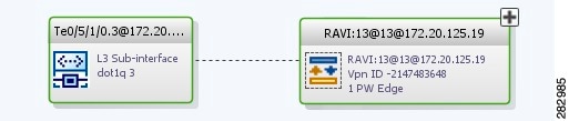
NE Logical Inventory Icons


NE Physical Inventory Icons
|
|
|
|---|---|

|
|

|
|

|
|

|
|

|
|

|
|

|
Links
The following sections describe link icons and characteristics:
Link Icons
|
|
|
|
|
|---|---|---|---|
|
|

|
||

|

|
||

|

|
||

|

|
||

|

|
||

|

|
||

|

|
||

|

|
||

|

|
||

|

|
||

|

|
||

|

|
||

|
|
||

|

|
||
|
|
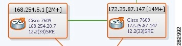
Link Colors
|
|
|
|
|---|---|---|

|
||

|
||

|
||

|
||

|
Link Characteristics
Severity Icons and Colors for Events, Tickets, and NEs
|
|
|
|
|---|---|---|

|
||

|
||

|
||

|
||

|
||

|
||

|
When new tickets are accumulated, a label is displayed in the navigation pane and map, based on the following formula:
|
|
|
|---|---|
The number of alarms with the highest severity that have the source as the network element and are part of the network element ticket(s). |
|
Buttons (Maps, Tables, Links, Events, Tickets, Reports)
The following topics describe the buttons used in the Vision client:
- Prime Network Vision Buttons
- Table Buttons
- Link Filtering Buttons
- Events client Buttons
- Ticket Properties Buttons
- Report Manager Buttons
Prime Network Vision Buttons


Table Buttons


Link Filtering Buttons


Events client Buttons


Ticket Properties Buttons


Report Manager Buttons
|
|
|
|
|---|---|---|

|
Enables you to define a report of this type that is suited specifically to your environment. |
|

|
||

|
||

|
||

|
||

|
||

|
||

|
Badges
Badges are small icons that appear with other network elements, such as element icons or links. The following topics describe the badges used by the Vision client and the Events client:
- VNE Communication State Badges
- VNE Investigation State Badges
- Network Element Technology-Related Badges
VNE Communication State Badges


VNE Investigation State Badges
|
|
|
|
|---|---|---|
A new VNE was created (and is starting); or an existing VNE was stopped. In this state, the VNE is managed and is validating support for the device type. (This investigation state is the equivalent of the Agent Not Loaded communication state.) A VNE remains in this state until it is started (or restarted) by a user. |
||

|
The device type is either not supported by Prime Network or is misconfigured (it is using the wrong scheme, or is using reduced polling but the device does not support it). To extend Prime Network functionality so that it recognizes unsupported devices, use the VNE Customization Builder. See the Cisco Prime Network 5.2 Customization Guide. |
|

|
The VNE is building the model of the device (the device type was found and is supported by Prime Network). A VNE remains in this state until all device commands are successfully executed at least once, or until there is a discovery timeout. |
|
The VNE has a stable model of the device. Modeling may not be fully complete, but there is enough information to monitor the device and make its data available to other applications, such as activation scripts. A VNE remains in this state unless it is stopped or moved to the maintenance state, or there are device errors. |
||

|
The VNE model is inconsistent with the device. This can be due to a variety of reasons; for a list of these reasons along with troubleshooting tips, see the topic on troubleshooting VNE investigation state issues in the Cisco Prime Network 5.2 Administrator Guide. |
|

|
VNE polling was suspended because it was manually moved to this state (by right-clicking the VNE and choosing Actions > Maintenance). The VNE remains in this state until it is manually restarted. A VNE in the maintenance state has the following characteristics:
The VNE is moved to the Stopped state if: it is VNE is moved, the parent AVM is moved or restarted, the parent unit switches to a standby unit, or the gateway is restarted. |
|

|
The VNE model is inconsistent with the device because a required device command failed, even after repeated retries. A common cause of this state is that the device contains an unsupported module. To extend Prime Network functionality so that it recognizes unsupported modules, use the VNE Customization Builder. See the Cisco Prime Network 5.2 Customization Guide. |
|

|
The VNE has been stopped or deleted by the user, and the VNE is terminating its connection to the device. |
|
The VNE process has terminated; it will immediately move to Defined Not Started. |
Network Element Technology-Related Badges
|
|
|
|
|
|---|---|---|---|

|
An MST or REP access gateway is associated with the element. |
||

|
The element associated with this badge has a REP alternate port. |
Viewing REP Information in VLAN Domain Views and VLAN Overlays |
|

|
The element associated with this badge has a REP primary port that is also blocking. |
Viewing REP Information in VLAN Domain Views and VLAN Overlays |
|

|
The element associated with this badge has a REP primary port. |
Viewing REP Information in VLAN Domain Views and VLAN Overlays |
|

|
|||

|
|||

|
The element associated with this badge is a backup pseudowire or a protected LSP. |
||

|
One or more links is represented by the visual link and at least one of the links contains a badge. |
Viewing REP Information in VLAN Domain Views and VLAN Overlays |
|

|
The element with this badge is associated with a network element that does not exist. For example, the device configuration has changed and a network problem exists. Some elements can be deleted only if their components, such as EFPs, VPLS forwards, or VRFs, display the reconciliation icon. |
Labelling NEs to Associate Them with Customers (Business Tags) |
|

|
The element associated with this badge is a STP root bridge or the root of an STP tree. |
Viewing STP Information in VLAN Domain Views and VLAN Overlays |
 Feedback