- Overview of Prime Network GUI clients
- Setting Up the Prime Network Clients
- Setting Up Change and Configuration Management
- Setting Up Vision Client Maps
- Setting Up Native Reports
- Setting Up Fault Management and the Events Client Default Settings
- Viewing Devices, Links, and Services in Maps
- Drilling Down into an NE’s Physical and Logical Inventories and Changing Basic NE Properties
- Manage Device Configurations and Software Images
- How Prime Network Handles Incoming Events
- Managing Tickets with the Vision Client
- Viewing All Event Types in Prime Network
- Cisco Path Tracer
- Managing IP Address Pools
- Monitoring AAA Configurations
- Managing DWDM Networks
- Managing MPLS Networks
- Managing Carrier Ethernet Configurations
- Managing Ethernet Networks Using Operations, Administration, and Maintenance Tools
- Monitoring Carrier Grade NAT Configurations
- Monitoring Quality of Service
- Managing IP Service Level Agreement (IP SLA) Configurations
- Monitoring IP and MPLS Multicast Configurations
- Managing Session Border Controllers
- Monitoring BNG Configurations
- Managing Mobile Transport Over Pseudowire (MToP) Networks
- Managing Mobile Networks
- Managing Data Center Networks
- Monitoring Cable Technologies
- Monitoring ADSL2+ and VDSL2 Technologies
- Monitoring Quantum Virtualized Packet Core
- VSS Redundancy System
- Icon Reference
- Permissions Required to Perform Tasks Using the Prime Network Clients
- Correlation Examples
- Managing certificates
Monitoring VSS Redundancy System
The following topics provide an overview of Cisco 6500 virtual switching redundancy system.
Cisco 6500 VSS Redundancy System Overview
The Cisco Catalyst 6500 Series Virtual Switching System (VSS) allows the clustering of two chassis units together into a single, logical entity. The two chassis units are connected through a Virtual switch link (VSL) link, where one chassis acts as an active unit and the another chassis acts as a standby unit. If the active chassis fails, then the standby chassis act as the active chassis. The chassis units are selected as the active or standby units based on the priority set.
This clustering of chassis allows enhancements in all areas of network design including high availability, scalability, management, and maintenance.
The VSS redundancy system has the following processors:
- Dual 6500 processor—Each chassis has 1 SUP card.
- Quad processor—Each chassis has 2 SUP cards, one is active and the other one is standby hot (switchover target). The chassis which is in standby hot (switchover target) acts as the next active chassis.
Viewing VSS Redundancy System Properties in Logical Inventory
To view the VSS redundancy system properties in the logical inventory:
Step 1![]() Double-click the Cat 6500 VSS device to open the Inventory window.
Double-click the Cat 6500 VSS device to open the Inventory window.
Step 2![]() Choose Logical Inventory> Redundancy Systems. Click a particular VSS domain ID. The properties of the VSS domain are displayed in the content pane.
Choose Logical Inventory> Redundancy Systems. Click a particular VSS domain ID. The properties of the VSS domain are displayed in the content pane.
Figure 32-1 shows the VSS redundancy system properties in the logical inventory
Figure 32-1 VSS Redundancy System Properties
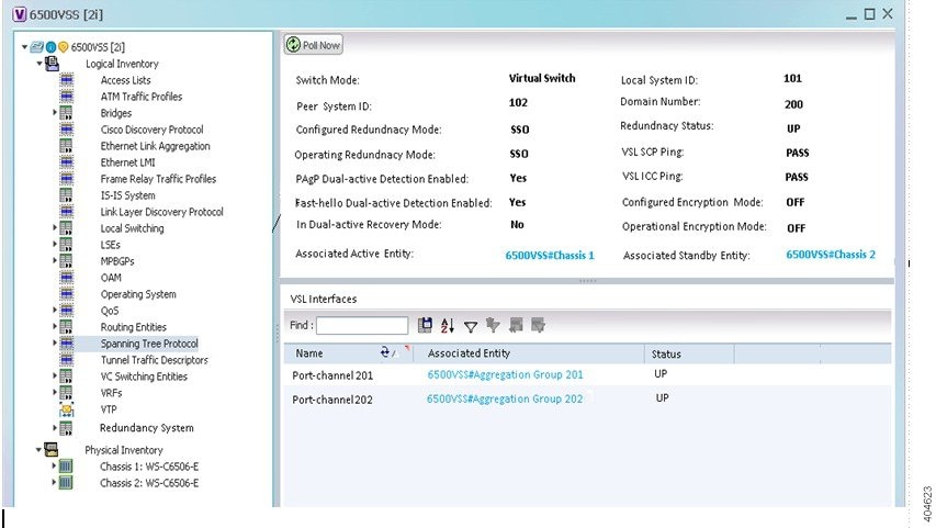
Table 32-1 describes the information that is displayed in the Redundancy System
Viewing Switch Virtual Redundancy State in Physical Inventory
To view the virtual switch redundancy state in the physical inventory:
Step 1![]() In the Vision client, double-click the Cat 6500 VSS device to open the Inventory window.
In the Vision client, double-click the Cat 6500 VSS device to open the Inventory window.
Step 2![]() In the Inventory window, expand the Physical Inventory node.
In the Inventory window, expand the Physical Inventory node.
Step 3![]() Click Chassis and click an SUP card.
Click Chassis and click an SUP card.
Step 4![]() In the SUP card details window, the VSS redundancy state is displayed.
In the SUP card details window, the VSS redundancy state is displayed.
Figure 32-2 depicts the redundancy states of virtual switching system:
Figure 32-2 Redundancy States of Virtual Switching System

Table 32-2 describes the information displayed for the VSL link:
Table 32-2 Virtual Switch Virtual Redundancy State
|
|
|
|---|---|
This RP is in standby state for this chassis (not ready to take over) |
|
Virtual Switch Link
Any device connected to VSS system, if there is a Virtual switch link (VSL) failure from the device to the first active chassis, then the system internally runs SSO and creates a VSL link with the second active chassis. Hence there is no network failure seen in the device connected to the VSS system.
Viewing VSL Link Properties
To view the VSL link properties between two virtual switches:
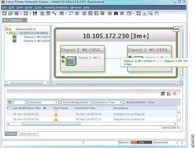
Step 1![]() In the Vision client map view, select a link connected between two chassis in Cat 6500 VSS device and open the link quick view window.
In the Vision client map view, select a link connected between two chassis in Cat 6500 VSS device and open the link quick view window.
Figure 32-3 depicts the VSS control links:
Step 2![]() In the link quick view window, click Properties.
In the link quick view window, click Properties.
Step 3![]() In the link properties window, select the VSL link to display the link properties.
In the link properties window, select the VSL link to display the link properties.
Figure 32-4 depicts the link properties:

Table 32-3 describes the information that is displayed for the VSL link
|
|
|
|---|---|
 Feedback