- Overview of Prime Network GUI clients
- Setting Up the Prime Network Clients
- Setting Up Change and Configuration Management
- Setting Up Vision Client Maps
- Setting Up Native Reports
- Setting Up Fault Management and the Events Client Default Settings
- Viewing Devices, Links, and Services in Maps
- Drilling Down into an NE’s Physical and Logical Inventories and Changing Basic NE Properties
- Manage Device Configurations and Software Images
- How Prime Network Handles Incoming Events
- Managing Tickets with the Vision Client
- Viewing All Event Types in Prime Network
- Cisco Path Tracer
- Managing IP Address Pools
- Monitoring AAA Configurations
- Managing DWDM Networks
- Managing MPLS Networks
- Managing Carrier Ethernet Configurations
- Managing Ethernet Networks Using Operations, Administration, and Maintenance Tools
- Monitoring Carrier Grade NAT Configurations
- Monitoring Quality of Service
- Managing IP Service Level Agreement (IP SLA) Configurations
- Monitoring IP and MPLS Multicast Configurations
- Managing Session Border Controllers
- Monitoring BNG Configurations
- Managing Mobile Transport Over Pseudowire (MToP) Networks
- Managing Mobile Networks
- Managing Data Center Networks
- Monitoring Cable Technologies
- Monitoring ADSL2+ and VDSL2 Technologies
- Monitoring Quantum Virtualized Packet Core
- VSS Redundancy System
- Icon Reference
- Permissions Required to Perform Tasks Using the Prime Network Clients
- Correlation Examples
- Managing certificates
Monitoring Cisco Virtualized Packet Core
The following topics provide an overview of Cisco Virtualized Packet Core (VPC) and describe the two configurations of VPC.
Overview of Cisco Virtualized Packet Core (VPC)
Cisco VPC is the industry's first hardware platform and hypervisor-independent solution that combines network functions virtualization (NfV) and software-defined networking (SDN). Cisco Virtualized Packet Core (VPC) provides a single solution for all the packet core services (4G, 3G, 2G, Wi-Fi, and small cell networks). As the network functions are provided as virtualized services, VPC enables a user to scale capacity and introduce new services in a faster and cost-effective manner.
Cisco VPC is based on the same proven StarOS software used in Cisco ASR 5000 Series platforms. VPC is mainly designed to distribute and orchestrate packet core functions across physical and virtual resources to enable users to perform the transition from physical to virtualized packet core services, or use both simultaneously.
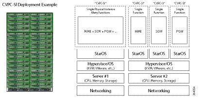
VPC–SI
With a single VM per virtual node, the VPC-SI is used as a solution for small to medium instances. Based on the StarOS, each VM deployed on the device supports a single function mapped to it. In general, VPC-SI supports SAE-GW, PGW, SGW, SGSN, and HNBGW services, and all the other mobility services that are supported by Cisco ASR5000.
Identifying VPC–SI VNE
To identify a VPC –SI device, follow the steps provided below:
Step 2![]() In the VNE Inventory window, verify if Device series is Virtual ASR 5K SI Series Mobile-Gateway.
In the VNE Inventory window, verify if Device series is Virtual ASR 5K SI Series Mobile-Gateway.
Step 3![]() Verify if the Element type is Virtual ASR 5K SI Mobile-Gateway.
Verify if the Element type is Virtual ASR 5K SI Mobile-Gateway.
Step 4![]() Verify if the Virtual device property is set to True.
Verify if the Virtual device property is set to True.
Figure 31-1 Deployment of VPC -SI VNE
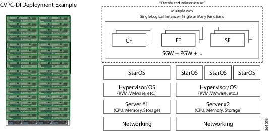
VPC–DI
The VPC-DI supports larger instances using multiple VMs. This capability is achieved by creating a distributed infrastructure by combining all the VMs in the virtual node to perform a single or multiple services. However, the VPC-DI is designed in such a way that the VMs have a single point of management. Based on StarOS, the VPC-DI supports distributed services (load balancing) across all VMs using a single service address.
At least one among the VMs is a MIO VM, and one or more VMs act as Fabric VMs and Service VMs. However, with StarOS 17, in the future releases, the fabric VM functionality will be intercoupled within the service VM and will not exist as separate VM.
Identifying VPC–DI VNE
To identify a VPC–DI device, follow the steps provided below:
Step 2![]() In the VNE inventory window, verify if Device series is Virtual ASR 5K DI Series Mobile-Gateway.
In the VNE inventory window, verify if Device series is Virtual ASR 5K DI Series Mobile-Gateway.
Step 3![]() Verify if the Element type is Virtual ASR 5K DI Mobile-Gateway.
Verify if the Element type is Virtual ASR 5K DI Mobile-Gateway.
Step 4![]() Verify if the Virtual device property is set to True.
Verify if the Virtual device property is set to True.
Figure 31-2 Deployment of VPC -DI VNE
UUID Support in Prime Network
In the absence of infrastructure monitoring tools like VCenter, the associations (hyperlinks) between Cisco Virtualized Packet Core (CvPC) VNE and the corresponding VCenter and UCS are not displayed in Prime Network. To identify a VM in the CvPC setup, UUID (a textual representation) is added in the physical inventory at the card level for all the virtual cards.
Viewing UUID Properties in Physical Inventory
To view UUID properties in the physical inventory:
Step 1![]() In the Vision client, double-click the device in which the CvPC is configured.
In the Vision client, double-click the device in which the CvPC is configured.
Step 2![]() In the VNE inventory window, expand the Physical Inventory node.
In the VNE inventory window, expand the Physical Inventory node.
Step 3![]() Choose Chassis > Server <Number>: Card A9K-VSM-500. The server configuration details are displayed in the content pane.
Choose Chassis > Server <Number>: Card A9K-VSM-500. The server configuration details are displayed in the content pane.
Step 4![]() Choose Server <Number>: Card A9K-VSM-500 > Subslot <Number>: Subcard -A9K-MODULEv. The slot details configured with UUID details is displayed in the content pane.
Choose Server <Number>: Card A9K-VSM-500 > Subslot <Number>: Subcard -A9K-MODULEv. The slot details configured with UUID details is displayed in the content pane.
Cisco Virtual Gateway Fault Correlation
The following table describes the fault correlations between CVPC devices and VMs:
|
|
|
|---|---|

Note![]() The faults correlations described in the above table are applicable only for virtual machines hosted in VMWare.
The faults correlations described in the above table are applicable only for virtual machines hosted in VMWare.
 Feedback