- Overview of Prime Network GUI clients
- Setting Up the Prime Network Clients
- Setting Up Change and Configuration Management
- Setting Up Vision Client Maps
- Setting Up Native Reports
- Setting Up Fault Management and the Events Client Default Settings
- Viewing Devices, Links, and Services in Maps
- Drilling Down into an NE’s Physical and Logical Inventories and Changing Basic NE Properties
- Manage Device Configurations and Software Images
- How Prime Network Handles Incoming Events
- Managing Tickets with the Vision Client
- Viewing All Event Types in Prime Network
- Cisco Path Tracer
- Managing IP Address Pools
- Monitoring AAA Configurations
- Managing DWDM Networks
- Managing MPLS Networks
- Managing Carrier Ethernet Configurations
- Managing Ethernet Networks Using Operations, Administration, and Maintenance Tools
- Monitoring Carrier Grade NAT Configurations
- Monitoring Quality of Service
- Managing IP Service Level Agreement (IP SLA) Configurations
- Monitoring IP and MPLS Multicast Configurations
- Managing Session Border Controllers
- Monitoring BNG Configurations
- Managing Mobile Transport Over Pseudowire (MToP) Networks
- Managing Mobile Networks
- Managing Data Center Networks
- Monitoring Cable Technologies
- Monitoring ADSL2+ and VDSL2 Technologies
- Monitoring Quantum Virtualized Packet Core
- VSS Redundancy System
- Icon Reference
- Permissions Required to Perform Tasks Using the Prime Network Clients
- Correlation Examples
- Managing certificates
Monitoring ADSL2+ and VDSL2 Technologies
This chapter discusses the following technology enhancements in Prime Network:
These topics describe how to use the Vision client to manage these technologies. If you cannot perform an operation that is described in these topics, you may not have sufficient permissions; see Permissions for Managing DSL2+ and VDSL2.
Viewing the ADSL2+/VDSL2 Configuration Details
Asymmetric digital subscriber line (ADSL) is a type of digital subscriber line (DSL) technology, a data communications technology that enables faster data transmission over copper telephone 5.2 than a conventional voiceband modem can provide. It does this by utilizing frequencies that are not used by a voice telephone call.
ADSL2+ extends the capability of basic ADSL by doubling the number of downstream channels. The data rates can be as high as 24 Mbit/s downstream and up to 1.4 Mbit/s upstream depending on the distance from the DSLAM to the customer's premises. It is capable of doubling the frequency band of typical ADSL connections from 1.1 MHz to 2.2 MHz. This doubles the downstream data rates of the previous ADSL2 standard (which was up to 12 Mbit/s), and like the previous standards will degrade from its peak bitrate after a certain distance.
Very-high-bit-rate digital subscriber line (VDSL or VHDSL) is a digital subscriber line (DSL) technology providing data transmission faster than ADSL over a single flat untwisted or twisted pair of copper wires (up to 52 Mbit/s downstream and 16 Mbit/s upstream), and on coaxial cable (up to 85 Mbit/s down- and upstream); using the frequency band from 25 kHz to 12 MHz. These rates mean that VDSL is capable of supporting applications such as high-definition television, as well as telephone services (voice over IP) and general Internet access, over a single connection.
Very-high-bit-rate digital subscriber line 2 (VDSL2) is an access technology that exploits the existing infrastructure of copper wires that were originally deployed for traditional telephone service as a way of delivering very high speed internet access. The main high-speed link (e.g. a fibre optic connection) terminates at a hub near the customers' location. The existing copper wire infrastructure is then used to carry the high speed connection for the short remaining distance to the customers. It can be deployed from central offices, from fiber-optic connected cabinets located near the customer premises, or within buildings.
In Prime Network, the ADSL2+ and VDSL2 technologies are grouped under the XDSL Traffic Descriptors node.
To view the XDSL Traffic Descriptors Details:
Step 1![]() Right-click the required device in the Vision client and choose Inventory.
Right-click the required device in the Vision client and choose Inventory.
Step 2![]() Expand the Logical Inventory node and choose XDSL Traffic Descriptors. The relevant details are displayed in the content pane as shown in Figure 30-1.
Expand the Logical Inventory node and choose XDSL Traffic Descriptors. The relevant details are displayed in the content pane as shown in Figure 30-1.
Figure 30-1 XDSL Traffic Descriptor Details
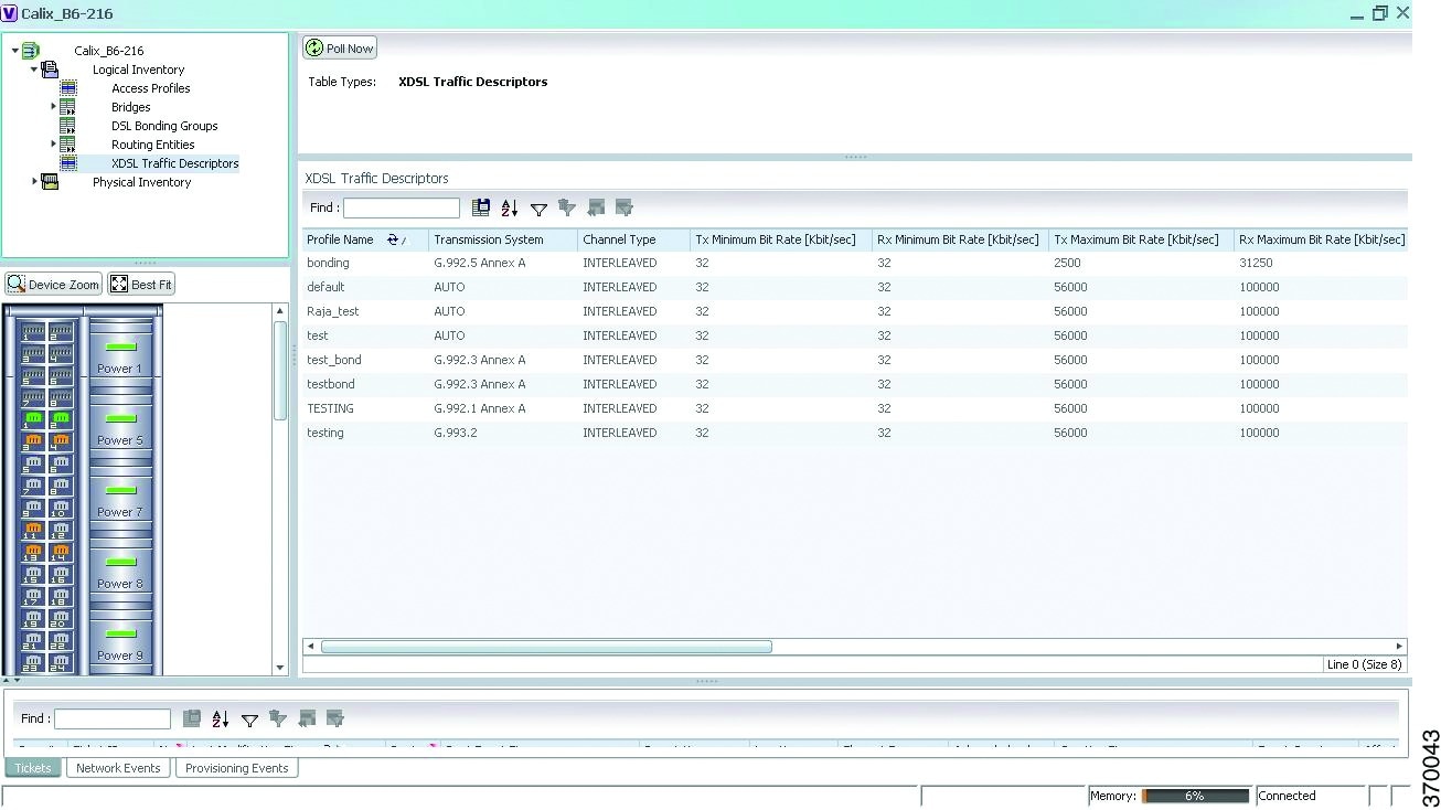
Table 30-1 describes the XDSL Traffic Descriptor details.
Viewing the ADSL2+/VDSL2 Details for a Device
The physical inventory details for a device displays the location information as well as the XDSL support details for ADSL2+ and VDSL2 devices,
To view the physical inventory details for a device:
Step 1![]() Right-click the required device in the Vision client and choose Inventory.
Right-click the required device in the Vision client and choose Inventory.
Step 2![]() Expand the Physical Inventory node.
Expand the Physical Inventory node.
Step 3![]() Choose the port and the following details are displayed in the content pane:
Choose the port and the following details are displayed in the content pane:
- Location Details—This section displays the Device Type, Location, Port Alias, and Status of the device. It also indicates whether alarms must be sent for any event or alarm.
- ATM on port—This section displays the Asynchronous Transfer Mode details for the port.
- PTM on port—This section displays the Packet Transfer Mode (PTM) details for the port. The PTM section displays the following information:
–![]() TPS-TC Admin Mode—Will be displayed only for VDSL line cards.
TPS-TC Admin Mode—Will be displayed only for VDSL line cards.
–![]() TPS-TC Oper Mode—Will be displayed only for VDSL line cards.
TPS-TC Oper Mode—Will be displayed only for VDSL line cards.

Note![]() The ATM on Port and PTM on Port sections will not be displayed if the port is bonded to a DSL group or if the TPS-TC Admin Mode is specified as Auto and the TPS-TC Oper Mode is specified as Unknown.
The ATM on Port and PTM on Port sections will not be displayed if the port is bonded to a DSL group or if the TPS-TC Admin Mode is specified as Auto and the TPS-TC Oper Mode is specified as Unknown.
- XDSL/ADSL2/2+—This section displays the XDSL support details. These support details include the Administrative and Operating statuses, Operating Mode, Aggregation Group, the various Bit rates and Noise margins.
The Operating Mode indicates whether the device is an ADSL2 or VDSL 2 device. The Aggregation Group indicates whether the port is associated to a DSL bonding group. This is a link, which when clicked will take you to the relevant bonding group in the DSL Bonding Group node.For more information about the attributes in this section, refer to Table 30-1 .
Note![]() The name of this section changes based on the value in the Operating Mode field. If the value in the Operating Mode field is None, then this section is titled XDSL. If the value in this field refers to a ADSL device (for example G.992.5 Annex A), then this section is titled ADSL Ver 2/2+. If the value in this field refers to a VDSL device (for example G.993.2), then this section is titled VDSL Ver2.
The name of this section changes based on the value in the Operating Mode field. If the value in the Operating Mode field is None, then this section is titled XDSL. If the value in this field refers to a ADSL device (for example G.992.5 Annex A), then this section is titled ADSL Ver 2/2+. If the value in this field refers to a VDSL device (for example G.993.2), then this section is titled VDSL Ver2.
Viewing the DSL Bonding Group Configuration Details
Channel bonding is a computer networking arrangement in which two or more network interfaces on a host computer are combined for redundancy or increased throughput. Similarly, multiple DSL 5.2 can be bonded to give higher bandwidth.
A bonded DSL uses multiple DSL connections and aggregates the bandwidth together to increase the speed of upload and download process.
To view the DSL bonding group details:
Step 1![]() Right-click the required device in the Vision client and choose Inventory.
Right-click the required device in the Vision client and choose Inventory.
Step 2![]() Expand the Logical Inventory node and choose DSL Bonding Groups. The relevant details are displayed in the content pane as shown in Figure 30-2.
Expand the Logical Inventory node and choose DSL Bonding Groups. The relevant details are displayed in the content pane as shown in Figure 30-2.
Figure 30-2 DSL Bonding Group Node
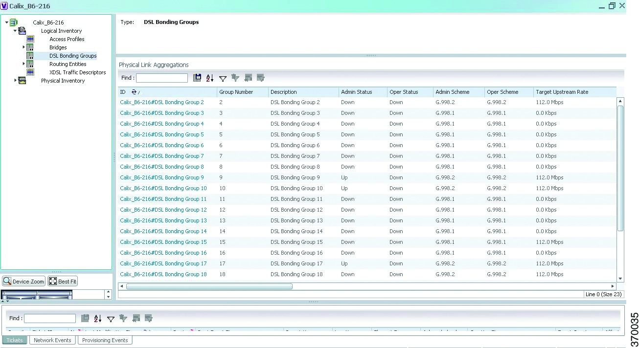
Table 30-2 describes the DSL Bonding Group details.
Viewing Transport Models Supported by ADSL2+ and VDSL2
In Prime Network, the following transport models are supported in the ADSL2+ and VDSL2 technologies:
- N-to-One—In this most commonly used model, a Service VLAN tag (S-Vid) is assigned to a service throughout the network. The destination is determined by the MAC address of the device and the service VLAN at the edge of the network. This transport model is supported on ADSL2+ and VDSL2 line cards.
- One-to-One—In this model, the destination is determined by a pair of VLAN tags, which must be unique throughout the network. This transport model is supported on B6 VDSL2 line cards.
- Transparent LAN Service (TLS) —This model allows transparency to the business customers while transporting business traffic between geographically disperse business endpoints. The traffic that is transported by the infrastructure that interconnects the locations is transparent to the carrier network (including protocols such as STP, unicast and multicast protocols). The traffic can be of any format and often includes VLAN tagged traffic.
Viewing the N-to-One Access Profile
To view the N-to-One access profile:
Step 1![]() Right-click the required device in the Vision client and choose Inventory.
Right-click the required device in the Vision client and choose Inventory.
Step 2![]() Expand the Logical Inventory node and choose N-to-One Access Profiles. The relevant details are displayed in the content pane as shown in Figure 30-3.
Expand the Logical Inventory node and choose N-to-One Access Profiles. The relevant details are displayed in the content pane as shown in Figure 30-3.
Figure 30-3 N-to-One Access Profile
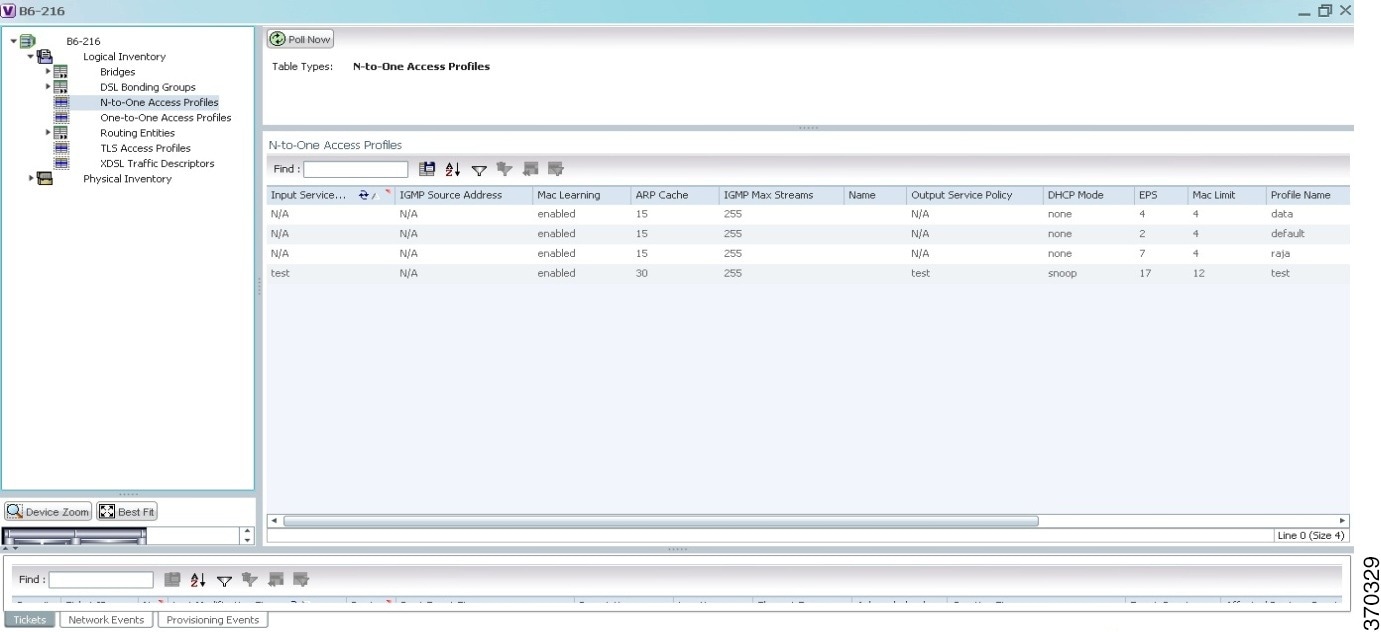
Table 30-3 describes the N-to-One Access Profile details.
Viewing the One-to-One Access Profile
To view the One-to-One access profile details, expand the logical inventory and choose One-to-One Access Profiles.
Figure 30-4 One-to-One Access Profile
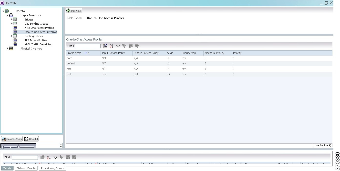
Table 30-4 describes the N-to-One Access Profile details.
Viewing the TLS Access Profile
To view the TLS access profile details:
Step 1![]() Right-click the required device in the Vision client and choose Inventory.
Right-click the required device in the Vision client and choose Inventory.
Step 2![]() Expand the Logical Inventory node and choose TLS Access Profiles. The relevant details are displayed in the content pane as shown in Figure 30-5.
Expand the Logical Inventory node and choose TLS Access Profiles. The relevant details are displayed in the content pane as shown in Figure 30-5.
Figure 30-5 TLS Access Profiles
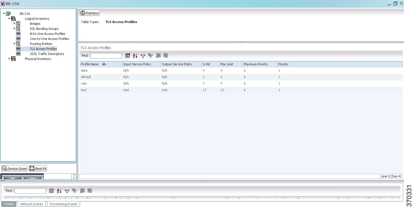
Table 30-5 describes the N-to-One Access Profile details.
 Feedback