- Overview of Prime Network GUI clients
- Setting Up the Prime Network Clients
- Setting Up Change and Configuration Management
- Setting Up Vision Client Maps
- Setting Up Native Reports
- Setting Up Fault Management and the Events Client Default Settings
- Viewing Devices, Links, and Services in Maps
- Drilling Down into an NE’s Physical and Logical Inventories and Changing Basic NE Properties
- Manage Device Configurations and Software Images
- How Prime Network Handles Incoming Events
- Managing Tickets with the Vision Client
- Viewing All Event Types in Prime Network
- Cisco Path Tracer
- Managing IP Address Pools
- Monitoring AAA Configurations
- Managing DWDM Networks
- Managing MPLS Networks
- Managing Carrier Ethernet Configurations
- Managing Ethernet Networks Using Operations, Administration, and Maintenance Tools
- Monitoring Carrier Grade NAT Configurations
- Monitoring Quality of Service
- Managing IP Service Level Agreement (IP SLA) Configurations
- Monitoring IP and MPLS Multicast Configurations
- Managing Session Border Controllers
- Monitoring BNG Configurations
- Managing Mobile Transport Over Pseudowire (MToP) Networks
- Managing Mobile Networks
- Managing Data Center Networks
- Monitoring Cable Technologies
- Monitoring ADSL2+ and VDSL2 Technologies
- Monitoring Quantum Virtualized Packet Core
- VSS Redundancy System
- Icon Reference
- Permissions Required to Perform Tasks Using the Prime Network Clients
- Correlation Examples
- Managing certificates
- Viewing Virtual Port Channel (vPC) Configurations
- Viewing CiscoFabricPath Configurations
- Viewing the Virtual Device Context and Port Allocation
Managing Data Center Networks
Data Center is a centralized repository, either physical or virtual for the storage, management, dissemination of data and information organized around a particular manner. In other words, it is a facility used to house computer systems and associated components, such as telecommunications and storage systems. It generally includes redundant or backup power supplies, redundant data communication connections, environmental controls such as air conditioning or fire suppression, and security devices.
Prime Network supports the following technologies as part of data center. If you cannot perform an operation that is described in these topics, you may not have sufficient permissions; see Permissions for Managing Data Center Networks.
Viewing Virtual Port Channel (vPC) Configurations
A Virtual Port Channel (vPC) allows links that are physically connected to two different Cisco Nexus 7000 or Cisco Nexus 5000 series network elements to appear as a single port channel by a third device as shown in Figure 28-1. The third device can be a switch, server, or any other networking device that supports port channels. A vPC can provide Layer 2 multipathing, which allows you to create redundancy and increase bisectional bandwidth by enabling multiple parallel paths between nodes and allowing load balancing traffic. You can use only Layer 2 port channels in the vPC.
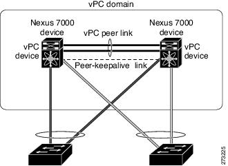
A vPC consists of the following components:
- Two vPC peer switches, among which one is primary and one is secondary. The system formed by the two peer switches is referred to as a vPC domain.
- A peer link, also known as multichassis EtherChannel trunk (MCT), which connects the vPC peer switches. A peer link is a redundant 10 Gigabit Ethernet Port Channel,which is used to carry traffic from one system to the other when needed and to synchronize forwarding tables.
- vPC member ports that form the PortChannel and are split between the vPC peers.
- A routed link, called as a vPC peer-keepalive or fault-tolerant link is a Layer 3 Gigabit Ethernet link, used to resolve dual-active scenarios where the peer link connectivity is lost.
A vPC domain is associated to a single Virtual Device Context (VDC), so all vPC interfaces belonging to a given vPC domain must be defined in the same VDC. You must have a separate vPC peer link and peer keepalive link infrastructure for each VDC deployed. Consolidating a vPC pair (two vPC peer devices of the same domain) in two VDCs of the same physical device is not supported. The vPC peer link must use 10-Gigabit Ethernet ports for both ends of the link; otherwise, the link will not be formed.
A vPC provides the following benefits:
- Allows a single device to use a port channel across two upstream devices
- Eliminates STP blocked ports
- Provides a loop-free topology
- Uses all available uplink bandwidth
- Provides fast convergence in case of link or a device failure
- Provides link level resiliency
- Assures high availability
Prime Network supports vPC on Cisco Nexus 5000 series and Cisco Nexus 7000 series network elements.
To view the vPC configuration details in Prime Network Vision:
Step 1![]() Right-click on the required device and choose the Inventory option.
Right-click on the required device and choose the Inventory option.
Step 2![]() In the Inventory window, choose Logical Inventory > VPC Domain. The vPC domain details are displayed in the content pane as shown in Figure 28-2.
In the Inventory window, choose Logical Inventory > VPC Domain. The vPC domain details are displayed in the content pane as shown in Figure 28-2.
Figure 28-2 vPC Domain in Logical Inventory
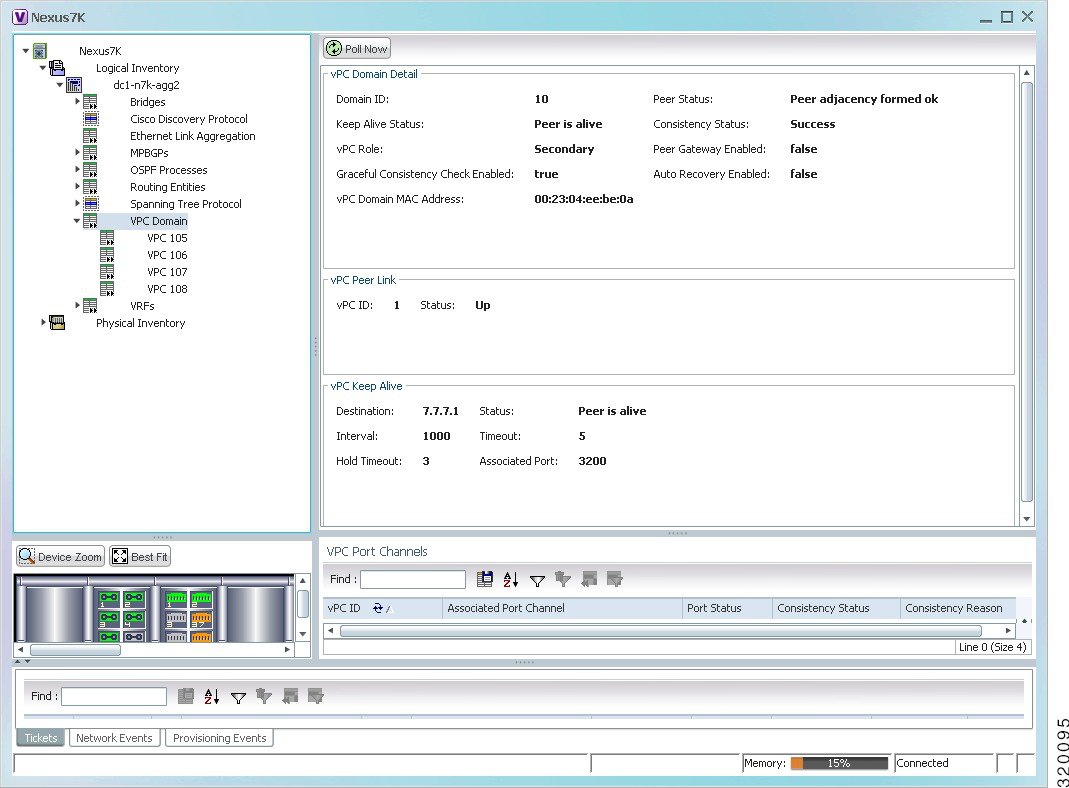
Table 28-1 describes the vPC domain details.
The following VPC commands can be launched from the inventory by right-clicking VPC Domain and choosing Commands > Show. Your permissions determine whether you can run these commands (see Permissions for Vision Client NE-Related Operations). To find out if a device supports these commands, see the Cisco Prime Network 5.2 Supported Cisco VNEs.
|
|
|
|
|---|---|---|
Use this command to view and confirm the port channel capacity details. |
||
Use this command to view the vPCs available for the selected domain. |
||
Viewing Cisco FabricPath Configurations
Cisco FabricPath is an innovation in Cisco NX-OS software that brings the stability and scalability of routing to Layer 2. It provides a foundation to build a scalable fabric—a network that itself looks like a single virtual switch from the perspective of its users. The switched domain does not have to be segmented anymore, providing data center–wide workload mobility. Because traffic is no longer forwarded along a spanning tree, the bisectional bandwidth of the network is not limited, and massive scalability is possible.
Cisco FabricPath introduces an entirely new Layer 2 data plane by encapsulating the frames entering the fabric with a header that consists of routable source and destination addresses. These addresses are the address of the switch on which the frame was received and the address of the destination switch to which the frame is heading. From there, the frame is routed until it is reaches the remote switch, where it is de-encapsulated and delivered in its original Ethernet format.
Cisco FabricPath provides the following features:
- Allows Layer 2 multipathing in the FabricPath network.
- Provides built-in loop prevention and mitigation with no need to use the Spanning Tree Protocol (STP).
- Provides a single control plane for unknown unicast, broadcast, and multicast traffic.
- Enhances mobility and virtualization in the FabricPath network.
The system randomly assigns a unique switch ID to each device that is enabled with FabricPath. After you enable FabricPath on the devices, you can configure an Ethernet interface or a port channel interface as a FabricPath interface. If one member of the port channel is in FabricPath mode, then all the other members will also be in FabricPath mode. After you configure the interface as a FabricPath interface, it automatically becomes a trunk port, capable of carrying traffic for multiple Virtual Local Area Networks (VLANs).
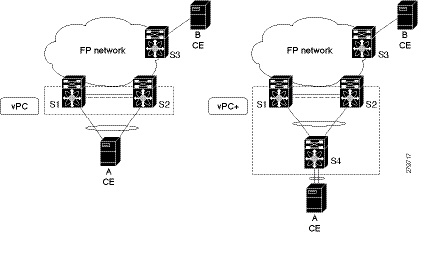
Prime Network supports Cisco FabricPath on Cisco Nexus 5000 series and Cisco Nexus 7000 series network elements. Figure 28-3 shows a Cisco FabricPath architecture.
Figure 28-3 Cisco FabricPath Architecture
To view the FabricPath configuration in Prime Network Vision:
Step 1![]() Right-click on the required device and choose the Inventory option.
Right-click on the required device and choose the Inventory option.
Step 2![]() In the Inventory window, choose Logical Inventory > FabricPath. The FabricPath configuration details are displayed in the content pane as shown in Figure 28-4. You can also view the properties, by right-clicking the FabricPath node and choosing Properties.
In the Inventory window, choose Logical Inventory > FabricPath. The FabricPath configuration details are displayed in the content pane as shown in Figure 28-4. You can also view the properties, by right-clicking the FabricPath node and choosing Properties.
Figure 28-4 Cisco FabricPath Node in Logical Inventory
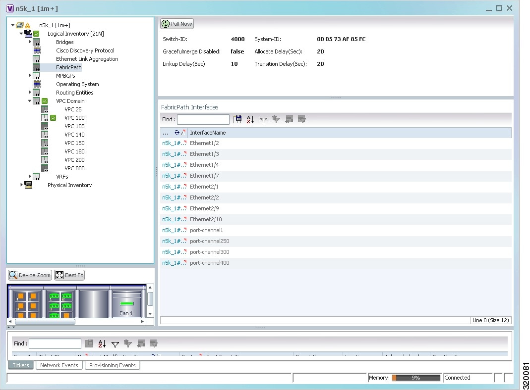
Table 28-2 describes the FabricPath configuration details.
The following FabricPath commands can be launched from the inventory by right-clicking FabricPath and choosing Commands > Show. Your permissions determine whether you can run these commands (see Permissions for Vision Client NE-Related Operations). To find out if a device supports these commands, see the Cisco Prime Network 5.2 Supported Cisco VNEs.
|
|
|
|
|---|---|---|
Use this command to view the MAC address-table learning mode. |
Viewing the Virtual Device Context and Port Allocation
The Virtual Device Context (VDC) partitions a single physical device into multiple logical devices that provide fault isolation, management isolation, address allocation isolation, service differentiation domains, and adaptive resource management. You can manage a VDC instance within a physical device independently. Each VDC appears as a unique device to the connected users. A VDC runs as a separate logical entity within the physical device, maintains its own unique set of running software processes, has its own configuration, and can be managed by a separate administrator.
In Prime Network, you can view the VDC context and port allocation details for a Nexus 7000 device. Each context will contain a list of allocated ports.
To view the VDC context details:
Step 1![]() Right-click on the Nexus 7000 device and choose the Inventory option.
Right-click on the Nexus 7000 device and choose the Inventory option.
Step 2![]() In the Inventory window, choose Logical Inventory > Context.
In the Inventory window, choose Logical Inventory > Context.
Step 3![]() In the content pane, click the Allocated Interfaces tab. The VDC context details are displayed in the content pane as shown in Figure 28-5. The Interface Name and the related Associated Entity are displayed in the content pane.
In the content pane, click the Allocated Interfaces tab. The VDC context details are displayed in the content pane as shown in Figure 28-5. The Interface Name and the related Associated Entity are displayed in the content pane.
Figure 28-5 Allocated Interfaces tab
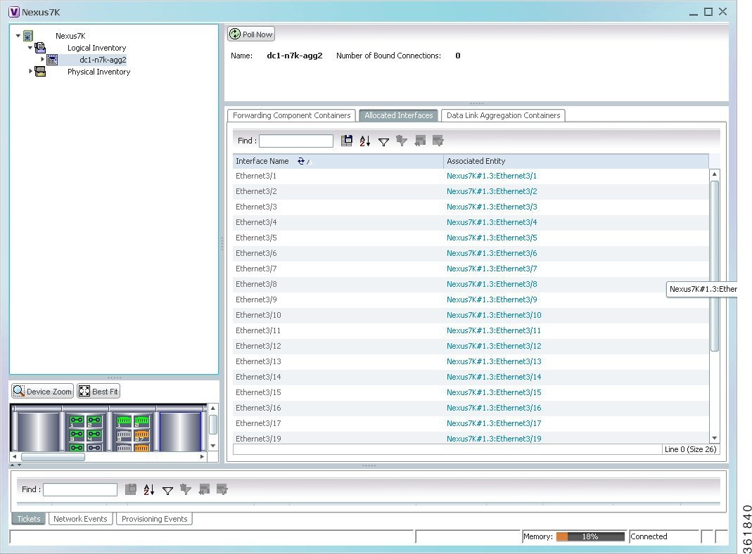
Step 4![]() Click the link in the Associated Entity field and you will be able to view the related interface node details under the Physical Inventory.
Click the link in the Associated Entity field and you will be able to view the related interface node details under the Physical Inventory.
Configuring Prompts and Messages for Unconfigured VDC for a Nexus Device
You can configure prompts and messages of unconfigured Virtual Device Context (VDC) for a Cisco Nexus device by using runRegTool.
Prime Network reads these prompts at the time of switching to unconfigured VDC to avoid collectors from blocking the expected prompt. When the prompts are completely read, Prime network receives the interactive mode response from the device, say Cisco Nexus device. Prime Network detects the situation by comparing the device response with the configured messages of unconfigured VDC in the Registry. After the situation is detected, Prime Network avoids configuring the unconfigured VDC by aborting the switchto command. As soon as the current command result is marked as Valid, you can proceed with inventory discovery.
If either Unconfigured VDC is configured or Suspended VDC is activated, click Poll Now to view the updated inventory details.

Note![]() Ensure that prompts and messages must be defined with a unique name and full description.
Ensure that prompts and messages must be defined with a unique name and full description.
To configure new prompts, run the below command:
To configure messages, run the below command:
Viewing Virtualized Resources
Virtualization is a concept of creating a virtual version of any resource, such as hardware platform, operating system, storage device, or network resources, as shown in Figure 28-6. It provides a layer of abstraction between computing, storage and networking hardware, and the applications running on it. Virtual infrastructure gives administrators the advantage of managing pooled resources across the enterprise, allowing IT managers to be more responsive to dynamic organizational needs and to better leverage infrastructure investments.
The VMware vCenter Server provides centralized management of virtualized hosts and virtual machines from a single console. With VMware vCenter Server, virtual environments are easier to manage: a single administrator can manage hundreds of workloads, more than doubling typical productivity in managing physical infrastructure.
In Prime Network, VCenter is modelled as a VNE.
Note![]() VCenter is created as a separate VNE using the Administration client. For more information about creating a new VNE, see the Cisco Prime Network 5.2 Administrator Guide. You must specify the http credentials for VCenter. However the SNMP credentials are optional, and the SSH credentials are not required.
VCenter is created as a separate VNE using the Administration client. For more information about creating a new VNE, see the Cisco Prime Network 5.2 Administrator Guide. You must specify the http credentials for VCenter. However the SNMP credentials are optional, and the SSH credentials are not required.
Figure 28-6 Virtualization Concept
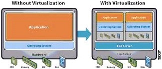
The various components of virtualization are:
A hypervisor, also called a blade server, a virtual machine manager, or a host server, is a program that allows multiple operating systems to share a single hardware host. Each operating system appears to have the host's processor, memory, and other resources all to itself. However, the hypervisor is actually controlling the host processor and resources, allocating what is needed to each operating system in turn and making sure that the guest operating systems (called virtual machines) do not disrupt each other.
A virtual representation of a real machine using software that provides an operating environment, which can run or host a guest operating system.
An operating system running in a virtual machine environment that would otherwise run directly on a separate physical system.
A data store represents a storage location for virtual machine files. It can be a Virtual Machine File System (VMFS) volume, a directory on Network Attached Storage, or a local file system path.
Data Center serves as a container for hosts, virtual machines, networks, and data stores.
A cluster is a collection of servers that operate as if it is a single machine. The primary purpose of these clusters is to provide uninterrupted access to data, even if a server loses network or storage connectivity, or fails completely, or if the application running on the server fails.
A resource pool is a logical abstraction for flexible management of resources. Resource pools can be grouped into hierarchies and used to hierarchically partition available CPU and memory resources.It is the foundation of virtual data centers, virtual desktops, high availability and other options on virtual servers. Resource pools aggregate CPU processing power and memory, along with any other relevant components, then share these hardware resources among virtual machines (VMs).
The following topics explain how to view and monitor virtual data center properties in Prime Network Vision:
- Viewing Virtual Data Centers
- Viewing the Data Stores of a Data Center
- Viewing the Host Servers of a Data Center
- Viewing all the Virtual Machines managed by vCenter
- Viewing the Virtual Machines of a Data Center
- Viewing the Host Cluster Details
- Viewing the Resource Pool Details
Viewing Virtual Data Centers
To view the virtual data centers in the logical inventory:
Step 1![]() Right-click on the required device and choose the Inventory option.
Right-click on the required device and choose the Inventory option.
Step 2![]() In the Inventory window, choose Logical Inventory > Compute Virtualization. The virtual data centers are listed in the content pane.
In the Inventory window, choose Logical Inventory > Compute Virtualization. The virtual data centers are listed in the content pane.
Table 28-3 describes the virtual data center properties.
|
|
|
|---|---|
IP address of the vCenter, which manages the virtual data center. |
|
Step 3![]() Right-click the data center and choose Properties to view more details.
Right-click the data center and choose Properties to view more details.
Viewing the Data Stores of a Data Center
To view the details of data stores available for a data center:
Step 1![]() Right-click on the required device and choose the Inventory option.
Right-click on the required device and choose the Inventory option.
Step 2![]() In the Inventory window, choose Logical Inventory > Compute Virtualization > Data Center > All Data Stores. The available data stores are displayed in the content pane. You can view the data store properties from the table or by right-clicking the required data store and choosing Properties.
In the Inventory window, choose Logical Inventory > Compute Virtualization > Data Center > All Data Stores. The available data stores are displayed in the content pane. You can view the data store properties from the table or by right-clicking the required data store and choosing Properties.
Table 28-4 describes the data store properties.
Viewing the Host Servers of a Data Center
To view the host centers of a data center:
Step 1![]() Right-click on the required device and choose the Inventory option.
Right-click on the required device and choose the Inventory option.
Step 2![]() In the Inventory window, choose Logical Inventory > Compute Virtualization > Data Center > All Host Servers. Choose a host server and the details are displayed in the content pane as shown in Figure 28-7.
In the Inventory window, choose Logical Inventory > Compute Virtualization > Data Center > All Host Servers. Choose a host server and the details are displayed in the content pane as shown in Figure 28-7.
Figure 28-7 Host Server Details
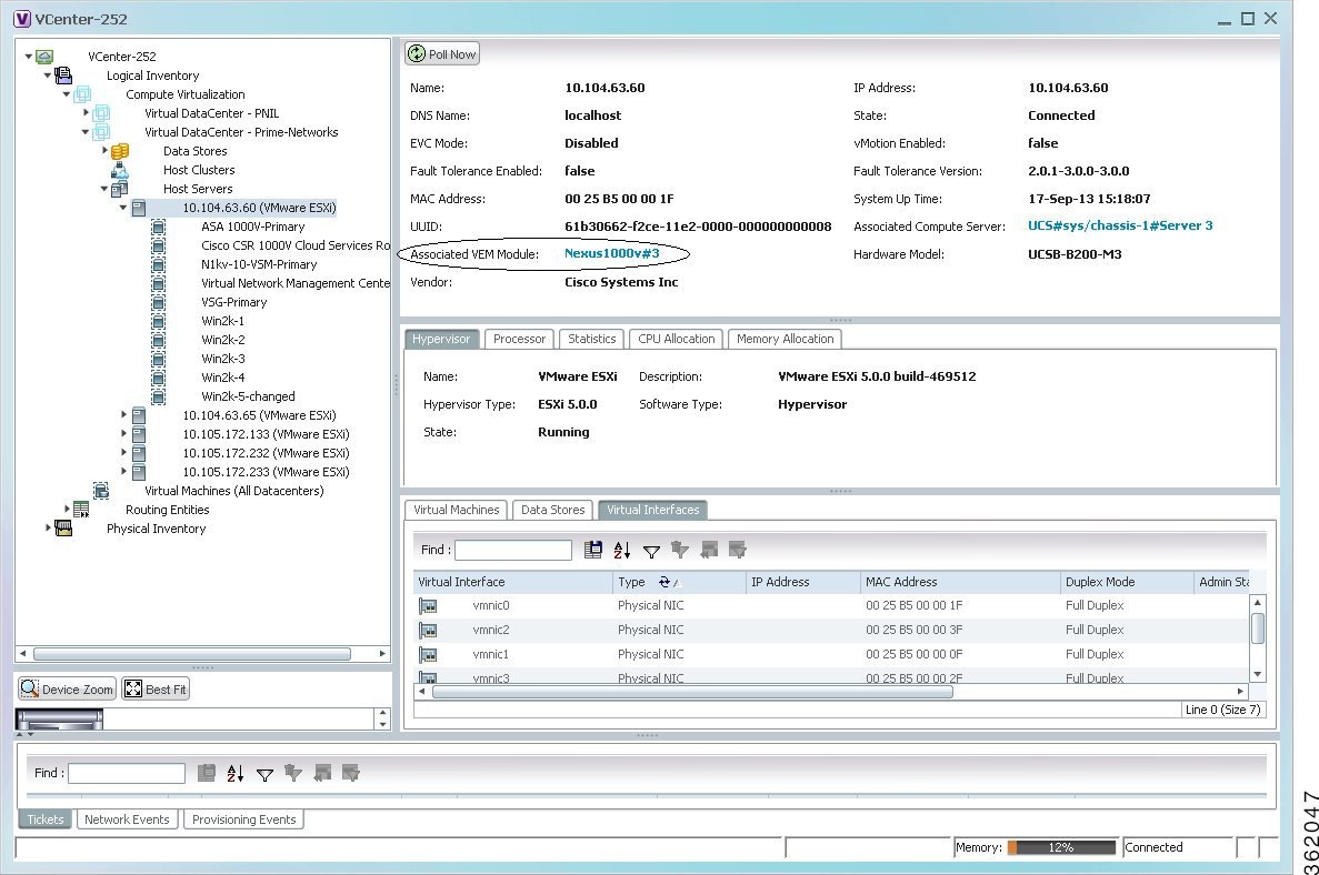
Table 28-5 describes the host server details.
Viewing all the Virtual Machines managed by vCenter
To view a list of all the virtual machines managed by a data center:
Step 1![]() Right-click on the required device and choose the Inventory option.
Right-click on the required device and choose the Inventory option.
Step 2![]() In the Inventory window, choose Logical Inventory > Compute Virtualization > Data Center > All Virtual Machines. A list of virtual machines is displayed in the content pane as shown in Step 3.
In the Inventory window, choose Logical Inventory > Compute Virtualization > Data Center > All Virtual Machines. A list of virtual machines is displayed in the content pane as shown in Step 3.
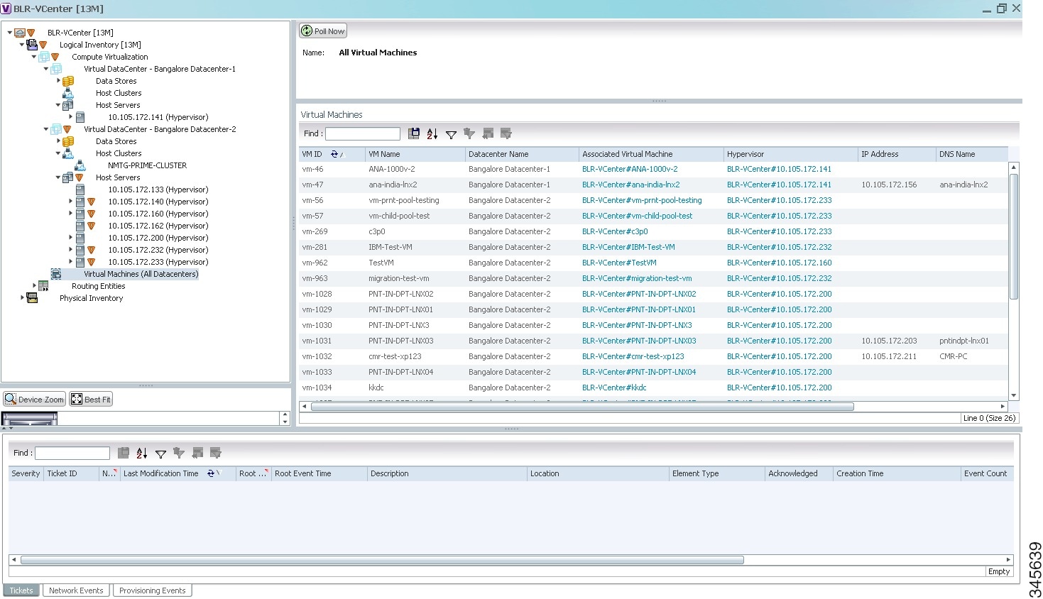
Table 28-6 describes the virtual machine details available in the list.
|
|
|
|---|---|
|
|
|
The name of the data center associated to the virtual machine. |
|
Viewing the Virtual Machines of a Data Center
To view the virtual machines for a data center:
Step 1![]() Right-click on the required device and choose the Inventory option.
Right-click on the required device and choose the Inventory option.
Step 2![]() In the Inventory window, choose Logical Inventory > Compute Virtualization > Data Center > All Host > Virtual Machine. A list of virtual machines is displayed in the content pane.
In the Inventory window, choose Logical Inventory > Compute Virtualization > Data Center > All Host > Virtual Machine. A list of virtual machines is displayed in the content pane.
Step 3![]() Click the hyperlinked virtual machine name to view more details about the virtual machine. Prime Network Vision takes you to the virtual machine node under the mapped host server in the logical inventory. You can view the virtual machine properties on the content pane or by right-clicking the virtual machine and choosing Properties.
Click the hyperlinked virtual machine name to view more details about the virtual machine. Prime Network Vision takes you to the virtual machine node under the mapped host server in the logical inventory. You can view the virtual machine properties on the content pane or by right-clicking the virtual machine and choosing Properties.
Table 28-7 describes the properties of the virtual machine.
Viewing the Host Cluster Details
To view the host cluster details:
Step 1![]() In the Vision client, right-click on the required device and select the Inventory option.
In the Vision client, right-click on the required device and select the Inventory option.
Step 2![]() In the Inventory menu, expand the Logical Inventory node.
In the Inventory menu, expand the Logical Inventory node.
Step 3![]() Select Compute Virtualization > Data Center > Host Clusters > Host cluster. The host cluster details are displayed in the content pane as shown in Figure 28-8.
Select Compute Virtualization > Data Center > Host Clusters > Host cluster. The host cluster details are displayed in the content pane as shown in Figure 28-8.
Figure 28-8 Host Cluster Details
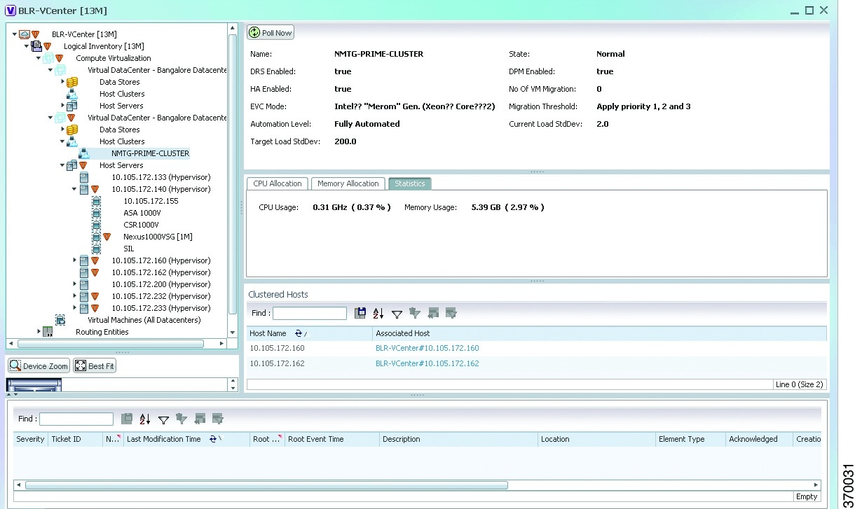
Table 28-8 describes the Host Cluster details.
Viewing the Resource Pool Details
To view the resource pool details:
Step 1![]() In the Vision client, right-click on the required device and select the Inventory option.
In the Vision client, right-click on the required device and select the Inventory option.
Step 2![]() In the Inventory menu, expand the Logical Inventory node.
In the Inventory menu, expand the Logical Inventory node.
Step 3![]() Select Compute Virtualization > Data Center > Host Clusters > Host cluster. The host cluster details are displayed in the content pane.
Select Compute Virtualization > Data Center > Host Clusters > Host cluster. The host cluster details are displayed in the content pane.
Note![]() Alternatively, you can also view the host cluster details by selecting Compute Virtualization > Data Center > All Host > Host.
Alternatively, you can also view the host cluster details by selecting Compute Virtualization > Data Center > All Host > Host.
Step 4![]() In the Compute Resource Pools tab in the content pane, click on a resource pool link in the Resource Pool field. The Compute Resource Pool Properties window is displayed.In
In the Compute Resource Pools tab in the content pane, click on a resource pool link in the Resource Pool field. The Compute Resource Pool Properties window is displayed.In
Table 28-10 describes the resource pool details.
Viewing the Map Node for an UCS Network Element
Using the Vision client, you can view the physical layout and topology among the multi-chassis devices on the map. The multi-chassis devices have more than one physical chassis, but they are represented as a single entity in Prime Network. In a map, this device is shown as an aggregation of all the device chassis. For more information on viewing multi-chassis devices, see Viewing Multi-Chassis Devices.
For a Cisco Unified Computing Service (UCS) device, you can view its chassis along with the other elements relevant to the UCS device, such as Blade Server and IO Modules.
Another important component of the UCS is the Fabric InterConnect. The Fabric InterConnect is a core part of the UCS device. It provides both network connectivity and management capabilities to all attached blades and chassis. All chassis, and therefore all blades, attached to the interconnects become part of a single, highly available management domain.
To view the physical inventory of a UCS:
Step 1![]() Right-click on the UCS device and choose the Inventory option.
Right-click on the UCS device and choose the Inventory option.
Step 2![]() In the Inventory window, expand the Physical Inventory node. The Chassis and Fabric Interconnect chassis are displayed below the node as shown in Figure 28-9.
In the Inventory window, expand the Physical Inventory node. The Chassis and Fabric Interconnect chassis are displayed below the node as shown in Figure 28-9.
Figure 28-9 Physical Inventory Node for a UCS Device
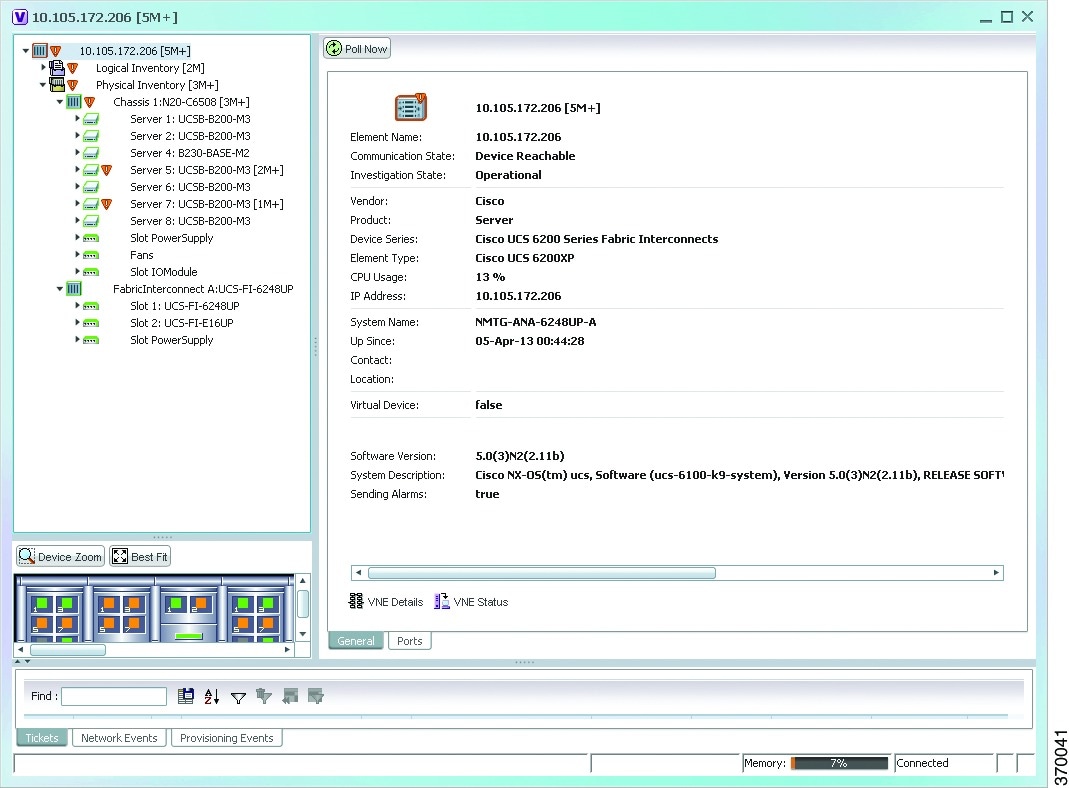
Step 3![]() Expand the Chassis node. The Blade servers, Fans, and the IO Modules that make up the Chassis are displayed under this node.
Expand the Chassis node. The Blade servers, Fans, and the IO Modules that make up the Chassis are displayed under this node.
Step 4![]() Expand the Fabric InterConnect node.The slots and the power supply are available here. You can click on each individual node under these nodes to view more details.
Expand the Fabric InterConnect node.The slots and the power supply are available here. You can click on each individual node under these nodes to view more details.
Step 5![]() Close the inventory window.
Close the inventory window.
Each of these parts, i.e. the blade servers, Fabric InterConnect chassis, and IO Modules, can be connected to each other internally. For example, an IO Module can be connected to a blade server or there could also be a link between the IO Module and Fabric InterConnect chassis.
The Ethernet links between the different components of a UCS can be categorized as:
- Backplane links—The links that connect a chassis to a backplane port via the IO Module.
- Fabric links—The links that connect a chassis to a Fabric InterConnect port via the IO Module.
You can also view this link in a map that contains a separate map node for each of the following elements:
The blade server chassis is shown as an aggregation that also contains the IO Module.
To view the map for a UCS device:
Step 1![]() In the Vision client, open a map with a UCS device. The UCS device is displayed with a plus (+) sign. Click on the + sign. The map containing the links between each element in the UCS device is shown in the window as shown in Figure 28-10.
In the Vision client, open a map with a UCS device. The UCS device is displayed with a plus (+) sign. Click on the + sign. The map containing the links between each element in the UCS device is shown in the window as shown in Figure 28-10.
Figure 28-10 UCS Map Node with Aggregation Links
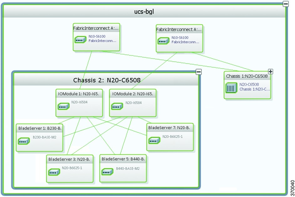
Note![]() Sub-nodes are available for the chassis that have blade servers under them. You can expand/contract these sub-nodes to view more details. However, the elements under the Fabric InterConnect chassis will not be displayed in the map.You can also view the inventory for an element by double-clicking on a node in the map. The inventory window will open with the selected node.
Sub-nodes are available for the chassis that have blade servers under them. You can expand/contract these sub-nodes to view more details. However, the elements under the Fabric InterConnect chassis will not be displayed in the map.You can also view the inventory for an element by double-clicking on a node in the map. The inventory window will open with the selected node.
Step 2![]() Hover your mouse cursor over the required link in a map. A link tooltip is displayed. The tooltip displays the link endpoints identified by the element or service name and the number of links represented by the line on the map.
Hover your mouse cursor over the required link in a map. A link tooltip is displayed. The tooltip displays the link endpoints identified by the element or service name and the number of links represented by the line on the map.
Step 3![]() To view additional link information, click the tooltip. The link quick view window is displayed. Alternatively, you can also double-click the link to view the link quick view window.
To view additional link information, click the tooltip. The link quick view window is displayed. Alternatively, you can also double-click the link to view the link quick view window.
Note![]() You can view links belonging to a specific type by clicking the Filter icon in the navigation pane and selecting the relevant check box. Open the link again and only the selected type of link is displayed. For more information about filtering a map, see Using Link Filters to Find Links.
You can view links belonging to a specific type by clicking the Filter icon in the navigation pane and selecting the relevant check box. Open the link again and only the selected type of link is displayed. For more information about filtering a map, see Using Link Filters to Find Links.
Step 5![]() In the map, double-click an element icon to open the Physical inventory and view the ports under it. For example, if you double-click on an IO Module element, the Inventory window is displayed along with the Backplane and Fabric ports under the IO Module node.
In the map, double-click an element icon to open the Physical inventory and view the ports under it. For example, if you double-click on an IO Module element, the Inventory window is displayed along with the Backplane and Fabric ports under the IO Module node.
Step 6![]() In the map, double click on a link to view it’s properties such as the link type, port alias, and port location. For more information on link properties, see Viewing Link Status and Detailed Link Properties.
In the map, double click on a link to view it’s properties such as the link type, port alias, and port location. For more information on link properties, see Viewing Link Status and Detailed Link Properties.
Note![]() The links between the UCS components can also be viewed in the Cisco Unified Computing System Manager application.
The links between the UCS components can also be viewed in the Cisco Unified Computing System Manager application.
Discovering the UCS Devices by Network Discovery
The Network Discovery feature automatically discovers network devices by traversing the network. The required information is an IP address for a seed device, and the SNMPv 2 or SNMPv 3 credentials. This information is added to a discovery profile that specifies the IP and SNMP information, along with any additional protocols or filters you want Prime Network to use.
You can also discover the UCS devices by Network Discovery. To manage a UCS device, the CLI and http credentials are required. However, the existing network discovery does not support http.
Since the CLI and http credentials are identical most of the times, the CLI credentials will be copied into http. You need to create a new discovery profile (using telnet or SSH credentials) for the UCS device and execute it. For more information about adding devices using Network Discovery, see the Cisco Prime Network 5.2 Administrator Guide.
Viewing the Virtual Network Devices of a Data Center
Prime Network supports the following virtual network devices of a data center:
Viewing the CSR 1000v Properties
The Cisco Cloud Services Router (CSR) 1000V is a single-tenant router in virtual form-factor that delivers comprehensive WAN gateway functionality to multi-tenant provider-hosted clouds. It is a software router that an enterprise or a cloud provider can deploy as a virtual machine (VM) in a provider-hosted cloud.The Cisco CSR 1000V provides selected Cisco IOS XE features on a virtualization platform. It also provides secure connectivity from the enterprise premise (such as a branch office or data center) to the public or private cloud. Figure 28-11 depicts the deployment of CSR 1000v on a provider hosted cloud:
Figure 28-11 Deployment of CSR 1000v on a Provider Hosted Cloud
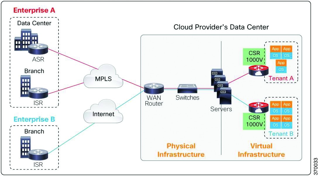
The Cisco CSR 1000V serves primarily as a router per tenant. In other words, since the CSR 1000v is situated on the tenant’s side, each tenant gets its dedicated routing instance and services (along with its own VPN connections, firewall policies, QoS rules, access control, and so on).
To view the CSR 1000v properties:
Step 1![]() In the Vision client, open a map that contains the CSR 1000v device.
In the Vision client, open a map that contains the CSR 1000v device.
Step 2![]() Right-click and choose the Inventory option to open the Inventory window.
Right-click and choose the Inventory option to open the Inventory window.
Step 3![]() In the Inventory window, click the device name to view the Element properties as shown in Figure 28-12. For more information about the properties window, see Drilling Down into the Properties of a Network Element.
In the Inventory window, click the device name to view the Element properties as shown in Figure 28-12. For more information about the properties window, see Drilling Down into the Properties of a Network Element.
Figure 28-12 Element Properties Window
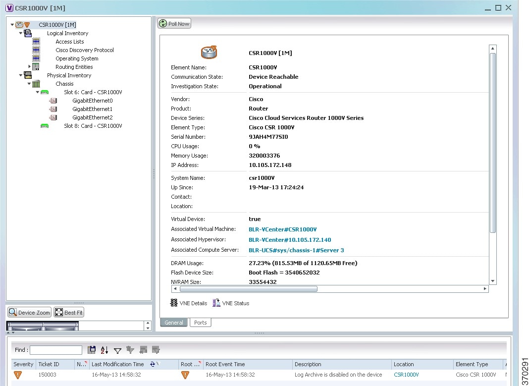
Note![]() The CSR 1000v device is associated with a hypervisor and physically available on a blade server. The links to the hypervisor and blade server are displayed in the Properties window.
The CSR 1000v device is associated with a hypervisor and physically available on a blade server. The links to the hypervisor and blade server are displayed in the Properties window.
Step 4![]() Under the Logical Inventory node, you can view the Access Lists, Cisco Discovery Protocol, Operating System requirements, and Routing Entities. For more information about the logical inventory properties, see Viewing the Logical Properties of a Device (Traffic, Routing, Information, Tunnels, Data Link Aggregations, Processes).
Under the Logical Inventory node, you can view the Access Lists, Cisco Discovery Protocol, Operating System requirements, and Routing Entities. For more information about the logical inventory properties, see Viewing the Logical Properties of a Device (Traffic, Routing, Information, Tunnels, Data Link Aggregations, Processes).
Step 5![]() Under the Physical Inventory node, you can view the two slots under the Chassis node.
Under the Physical Inventory node, you can view the two slots under the Chassis node.
Note![]() The first slot contains the Route Processor with three interface ports—one for management and the other two for data traffic. The second slot contains the Embedded Services Processor.
The first slot contains the Route Processor with three interface ports—one for management and the other two for data traffic. The second slot contains the Embedded Services Processor.
Viewing the Nexus 1000V Properties
The Cisco Nexus 1000V device is a a distributed virtual switch solution that is fully integrated within VMware Virtual Infrastructure, including VMware vCenter for the virtualization administrator. This solution off loads the configuration of the virtual switch and port groups to the network administrator to enforce a consistent datacenter network policy. It manages a data center defined by a VirtualCenter. Each server in the data center is represented as a module and can be managed as if it were a module in a physical Cisco switch.
The Cisco Nexus 1000V has the following components that can virtually emulate a 66-slot modular Ethernet switch with redundant supervisor functions:
- Virtual Ethernet module (VEM)—The Virtual Ethernet Module (VEM) is one part of the Cisco Nexus 1000V device that actually switches data traffic. Several VEMs are controlled by one VSM. All the VEMs that form a switch domain should be in the same virtual Data Center as defined by VMware VirtualCenter.
- Virtual supervisor module (VSM)—The VSM is a standalone, external, physical or virtual appliance that performs the following functions for the Cisco Nexus 1000V system (that is, the combination of the VSM itself and all VEMs it controls):
–![]() Integration with VMware vCenter
Integration with VMware vCenter
In the Cisco Nexus 1000V, traffic is switched between virtual machines locally at each VEM instance. Each VEM also interconnects the local virtual machine with the rest of the network through the upstream access-layer network switch (blade, top-of-rack, end-of-row, and so forth). The VSM runs the control plane protocols and configures the state of each VEM accordingly, but it never forwards packets.
In Prime Network, you can view the connectivity between the Nexus 1000V device and the host and blade server as shown in Figure 28-13.
Figure 28-13 Connectivity between Nexus 1000V and host/blade server
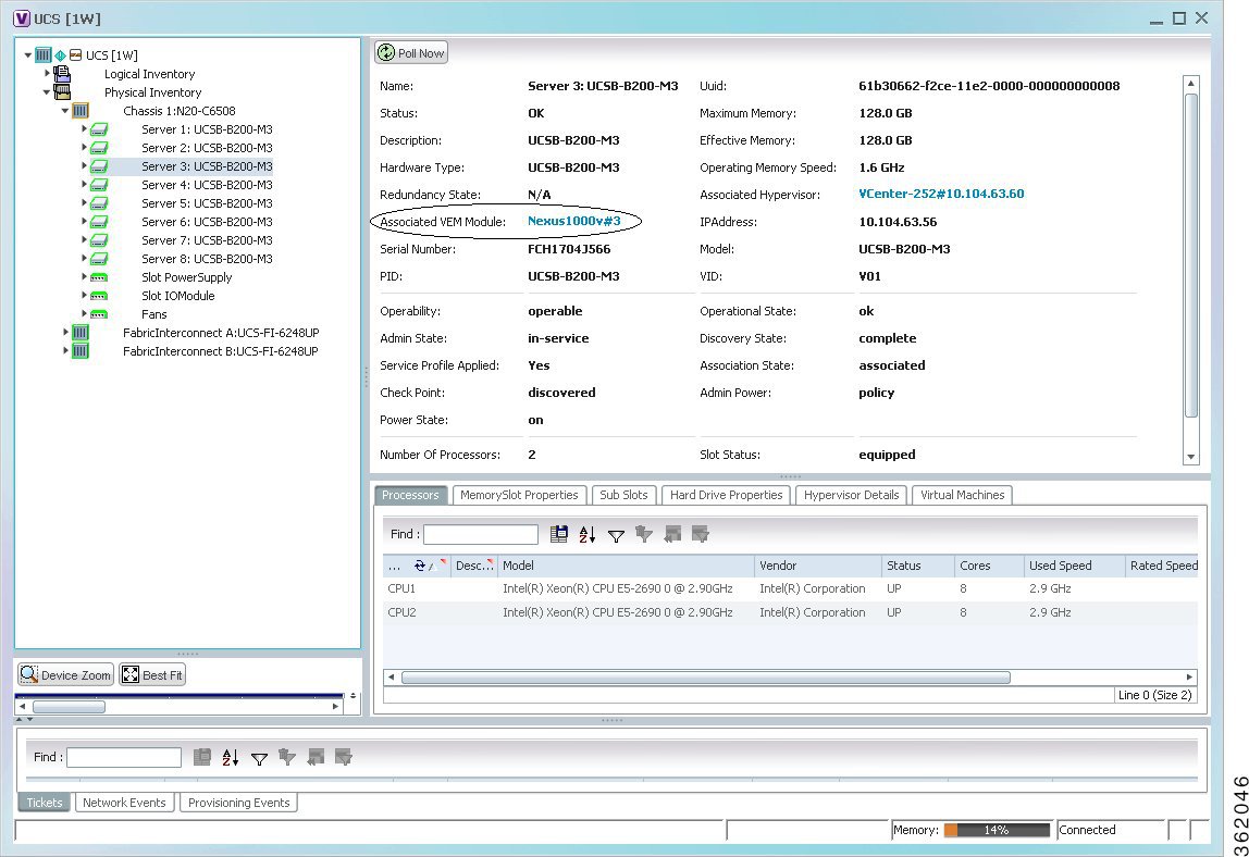
In other words, you can view the hosts under vCenter to which the device provides switching support and the underlying blade servers that are connected to the device.
Step 1![]() Right-click on the vCenter device and choose the Inventory option.
Right-click on the vCenter device and choose the Inventory option.
Step 2![]() In the Inventory window, choose Logical Inventory > Compute Virtualization > Virtual Data Center > Host Servers > Host Server.
In the Inventory window, choose Logical Inventory > Compute Virtualization > Virtual Data Center > Host Servers > Host Server.
Step 3![]() In the content pane, click the link in the Associated VEM Module field. You can view the details of the UCS blade server of the Nexus 1000v device to which the vCenter is connected to.
In the content pane, click the link in the Associated VEM Module field. You can view the details of the UCS blade server of the Nexus 1000v device to which the vCenter is connected to.
Viewing the VSG Properties
The Cisco Virtual Security Gateway (VSG) is a virtual firewall appliance that provides trusted access to virtual data center and cloud environments. The Cisco VSG enables a broad set of multi tenant workloads that have varied security profiles to share a common compute infrastructure in a virtual data center private cloud or in a public cloud. By associating one or more virtual machines (VMs) into distinct trust zones, the Cisco VSG ensures that access to trust zones is controlled and monitored through established security policies.
Figure 28-14 depicts the deployment of VSG:
Figure 28-14 Deployment of VSG
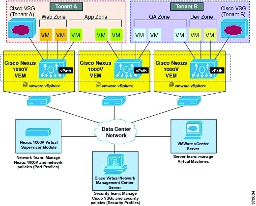
The Cisco VSG operates with the Cisco Nexus 1000V in the VMware vSphere hypervisor, and the Cisco VSG leverages the virtual network service datapath (vPath) that is embedded in the Nexus 1000V Virtual Ethernet Module (VEM). A VEM can be associated to a Cisco VSG.
Step 1![]() In the Vision client, open a map that contains the VSG device.
In the Vision client, open a map that contains the VSG device.
Step 2![]() Right-click and choose the Inventory option to open the Inventory window.
Right-click and choose the Inventory option to open the Inventory window.
Step 3![]() In the Inventory window, click the device name to view the Element properties. For more information about the properties window, see Drilling Down into the Properties of a Network Element
In the Inventory window, click the device name to view the Element properties. For more information about the properties window, see Drilling Down into the Properties of a Network Element
Note![]() The VSG device is associated with a hypervisor and physically available on a blade server. The links to the hypervisor and blade server are displayed in the Properties window.
The VSG device is associated with a hypervisor and physically available on a blade server. The links to the hypervisor and blade server are displayed in the Properties window.
Step 4![]() Under the Logical Inventory node, you can view the Access Lists, Cisco Discovery Protocol, Operating System requirements, and Routing Entities. For more information about the logical inventory properties, see Viewing the Logical Properties of a Device (Traffic, Routing, Information, Tunnels, Data Link Aggregations, Processes).
Under the Logical Inventory node, you can view the Access Lists, Cisco Discovery Protocol, Operating System requirements, and Routing Entities. For more information about the logical inventory properties, see Viewing the Logical Properties of a Device (Traffic, Routing, Information, Tunnels, Data Link Aggregations, Processes).
Step 5![]() Under the Physical Inventory node, you can view only one slot.
Under the Physical Inventory node, you can view only one slot.
Viewing the Compute Server Support Details
Prime Network provides support for the following compute servers:
- UCS B-Series Servers—The Cisco UCS B-Series Blade Servers are crucial building blocks of the Cisco Unified Computing System and are designed to increase performance, energy efficiency, and flexibility for demanding virtualized and non virtualized applications. Each Cisco UCS B-Series Blade Server uses converged network adapters (CNAs) for access to the unified fabric. This design reduces the number of adapters, cables, and access-layer switches while still allowing traditional LAN and SAN connectivity.
- UCS C-Series Servers—Cisco UCS C-Series Rack Servers deliver unified computing in an industry-standard form factor to reduce total cost of ownership and increase agility
- Third party or Non-Cisco servers—Includes support for non-UCS servers such as HP, Dell or IBM.
In Prime Network, the UCS B-Series and UCS C-Series servers are modelled as part of the UCS VNE. The UCS C-Series (standalone) and non-Cisco servers are modelled as individual VNEs.
Note![]() For a Cisco UCS device, you can also view the physical inventory, which includes the blade server, Fabric InterConnect and IO Modules. You can also view the physical layout and topology for the UCS device on the map. For more information, see Viewing the Map Node for an UCS Network Element.
For a Cisco UCS device, you can also view the physical inventory, which includes the blade server, Fabric InterConnect and IO Modules. You can also view the physical layout and topology for the UCS device on the map. For more information, see Viewing the Map Node for an UCS Network Element.
Note![]() There is also a direct correlation between the blade server and its associated virtual entities. For instance, if the blade server is shut down, then the associated entities such as the virtual machines and hypervisor will also be shut down.
There is also a direct correlation between the blade server and its associated virtual entities. For instance, if the blade server is shut down, then the associated entities such as the virtual machines and hypervisor will also be shut down.
To view the UCS server details:
Step 1![]() In the Vision client, right-click a UCS device and choose the Inventory option.
In the Vision client, right-click a UCS device and choose the Inventory option.
Step 2![]() In the Inventory window, expand the Physical Inventory node.
In the Inventory window, expand the Physical Inventory node.
Step 3![]() Select Chassis > Blade Server. The blade server configuration details are displayed in the content pane as shown in Figure 28-15.
Select Chassis > Blade Server. The blade server configuration details are displayed in the content pane as shown in Figure 28-15.
Figure 28-15 Blade Server Configuration Details
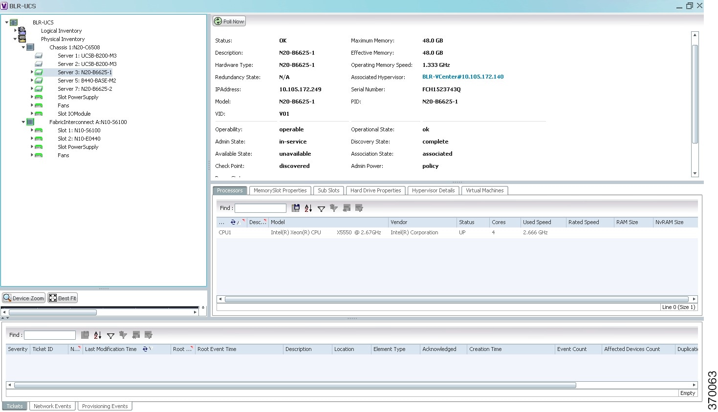
Table 28-10 describes the configuration details of a blade server.
Note![]() The Hypervisor and Virtual Machine tabs will be displayed only if the compute server is managed by a VMware VCenter, which is monitored by the same instance of Prime Network.
The Hypervisor and Virtual Machine tabs will be displayed only if the compute server is managed by a VMware VCenter, which is monitored by the same instance of Prime Network.
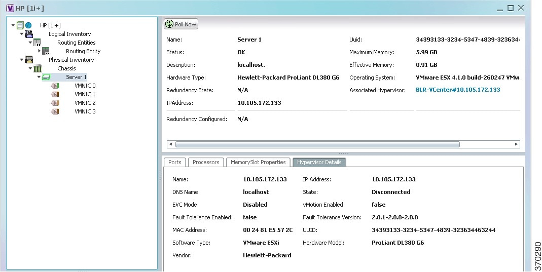
Viewing the Non Cisco Server Details
In Prime Network, non Cisco servers such as IBM, HP, and Dell are modeled as individual VNEs. These servers are modeled based on the operating system installed on them, and not on the native hardware pr management applications (except Supported Management Applications) running on these hardware.
The following operating systems are supported for modeling:
- Windows
- Linux
- VMWare ESXi
- Any other operating system that supports MIB2, RFC-1213-MIB, HOST-RESOURCE-MIB
Supported Management Applications
Prime Network supports only the following Linux-based management applications as individual VNEs:
Note![]() When ESXi is modeled on VMWare, ensure that SSH is also modeled along with it.
When ESXi is modeled on VMWare, ensure that SSH is also modeled along with it.
To view the non Cisco server details:
Step 1![]() In the Vision client, right-click Non-Cisco device and choose the Inventory option.
In the Vision client, right-click Non-Cisco device and choose the Inventory option.
Step 2![]() In the Inventory window, expand the Physical Inventory node.
In the Inventory window, expand the Physical Inventory node.
Step 3![]() Select the Server node. The server configuration details are displayed in the content pane along with the details of the operating system available in the server. The following tabs are also available:
Select the Server node. The server configuration details are displayed in the content pane along with the details of the operating system available in the server. The following tabs are also available:
Viewing the Mapping between the Compute Server and Hypervisor
The Cisco and non Cisco servers also support hypervisory functions to support various operating systems. Prime Network allows you to view the mapping details between the compute server and the hypervisor.
To view the mapping between the compute server and hypervisor:
Step 1![]() In the Vision client, right-click a UCS device and choose the Inventory option.
In the Vision client, right-click a UCS device and choose the Inventory option.
Step 2![]() In the Inventory window, expand the Physical Inventory node.
In the Inventory window, expand the Physical Inventory node.
Step 3![]() Select Chassis > Blade Server. The blade server configuration details are displayed in the content pane.
Select Chassis > Blade Server. The blade server configuration details are displayed in the content pane.
Step 4![]() Click the link in the Associated Hypervisor field to go to the relevant hypervisor under the vCenter node. The details of the hypervisor are displayed in the content pane, which also includes the Associated Compute Server field that contains a link to the relevant compute server.
Click the link in the Associated Hypervisor field to go to the relevant hypervisor under the vCenter node. The details of the hypervisor are displayed in the content pane, which also includes the Associated Compute Server field that contains a link to the relevant compute server.
Each blade server under the Chassis in the Physical inventory will link to the associated hypervisor. This is also applicable to the third party servers. In other words, the third party server also contains a link to the associated hypervisor.
Viewing the Storage Area Network Support Details
A storage area network (SAN) is a dedicated network that provides access to consolidated, block level data storage. SANs are primarily used to make storage devices, such as disk arrays, tape libraries, and optical jukeboxes, accessible to servers so that the devices appear like locally attached devices to the operating system. A SAN typically has its own network of storage devices that are generally not accessible through the local area network by other devices.
A virtual storage area network (VSAN) is a collection of ports from a set of connected Fibre Channel switches, that form a virtual fabric. Ports within a single switch can be partitioned into multiple VSANs, despite sharing hardware resources. Conversely, multiple switches can join a number of ports to form a single VSAN.
Most storage networks use the SCSI protocol for communication between servers and disk drive devices. A mapping layer to other protocols is used to form a network.
In Prime Network, the following technologies are used for storage area networks:
- Fibre Channel (FC)—Fibre Channel is a high-speed network technology (commonly running at 2-, 4-, 8- and 16-gigabit speeds) primarily used for storage networking. It was primarily used in the supercomputer field, but has now become the standard connection type for storage area networks (SAN) in enterprise storage. Fibre Channel can help with design of large-scale, storage-intensive systems. It can also provide a solution that allows rapid storage and retrieval of information, while simplifying the interconnection of different components in the system
- Fibre Channel over Ethernet (FCoE)—Fibre Channel over Ethernet is an encapsulation of Fibre Channel frames over Ethernet networks. This allows Fibre Channel to use 10 Gigabit Ethernet networks (or higher speeds) while preserving the Fibre Channel protocol. It drastically reduces the number of I/O adapters, cables, and switches in the data center, while providing a wire-once, agile infrastructure. Based on lossless, reliable 10 Gigabit Ethernet, FCoE networks combine LAN and multiple storage protocols on a single converged network.
For information on the devices that support VSAN, refer to Cisco Prime Network 4.1 Supported VNEs.
Note![]() The Cisco Fabric InterConnect UCS devices only supports the Fibre Channel over Ethernet technology.
The Cisco Fabric InterConnect UCS devices only supports the Fibre Channel over Ethernet technology.
Viewing the Storage Area Network Configuration Details
To view the VSAN configuration details:
Step 1![]() In the Vision client, right-click the required device and choose the Inventory option.
In the Vision client, right-click the required device and choose the Inventory option.
Step 2![]() In the Inventory window, expand the Logical Inventory node.
In the Inventory window, expand the Logical Inventory node.
Step 3![]() Select VSANs > VSAN service. The VSAN configuration details are displayed in the content pane as shown in the Figure 28-16.
Select VSANs > VSAN service. The VSAN configuration details are displayed in the content pane as shown in the Figure 28-16.
Figure 28-16 VSAN Configuration Details
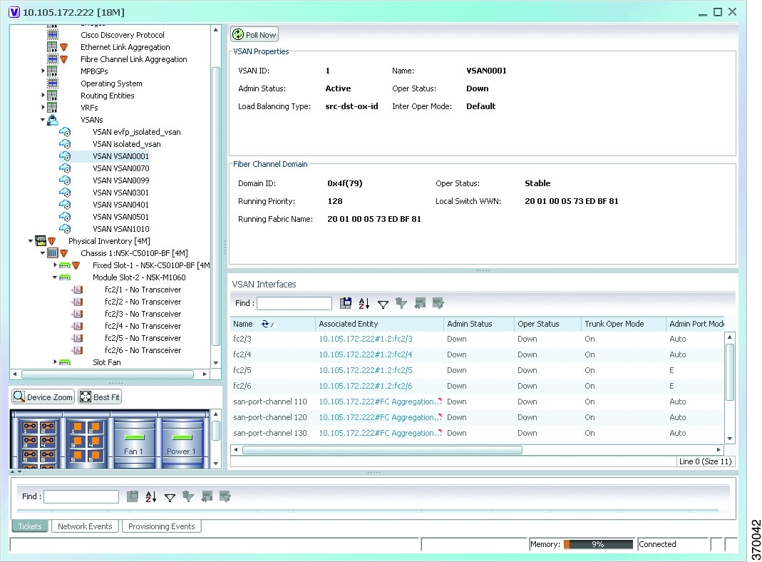
Table 28-10 describes the VSAN configuration details.
Note![]() For more information about the alarms relating to FC and FCoE, see the Cisco Prime Network 5.2 Supported Service Alarms.
For more information about the alarms relating to FC and FCoE, see the Cisco Prime Network 5.2 Supported Service Alarms.
Viewing the FC Interface Details
To view the FC Interface details:
Step 1![]() In the Vision client, right-click the required device and choose the Inventory option.
In the Vision client, right-click the required device and choose the Inventory option.
Step 2![]() In the Inventory window, expand the Physical Inventory node.
In the Inventory window, expand the Physical Inventory node.
Step 3![]() Select Chassis > Module Slot > Fibre channel interface. The FC interface details are displayed in the content pane.
Select Chassis > Module Slot > Fibre channel interface. The FC interface details are displayed in the content pane.
Table 28-11 describes the FC configuration details.
Viewing the FCoE Interface Details
To view the FCoE Interface details:
Step 1![]() In the Vision client, right-click the required device and choose the Inventory option.
In the Vision client, right-click the required device and choose the Inventory option.
Step 2![]() In the Inventory window, expand the Physical Inventory node.
In the Inventory window, expand the Physical Inventory node.
Step 3![]() Select Chassis > Fixed Slot > FCoE interface. The FCoE interface details are displayed in the content pane. The following information is displayed in the content pane:
Select Chassis > Fixed Slot > FCoE interface. The FCoE interface details are displayed in the content pane. The following information is displayed in the content pane:
Table 28-12 describes the FCoE configuration details.
Note![]() For more information about the other sections in this window, see Table 28-11.
For more information about the other sections in this window, see Table 28-11.
Viewing the Fibre Channel Link Aggregation
To view the Fiber Channel Link Aggregation details:
Step 1![]() In the Vision client, right-click the required device and choose the Inventory option.
In the Vision client, right-click the required device and choose the Inventory option.
Step 2![]() In the Inventory window, expand the Logical Inventory node.
In the Inventory window, expand the Logical Inventory node.
Step 3![]() Select the Fibre Channel Link Aggregation option. The list of aggregations are displayed in the content pane.
Select the Fibre Channel Link Aggregation option. The list of aggregations are displayed in the content pane.
Step 4![]() Double-click on an aggregation. The Fibre Channel Link Aggregation Properties window is displayed as shown in Figure 28-17.
Double-click on an aggregation. The Fibre Channel Link Aggregation Properties window is displayed as shown in Figure 28-17.
Figure 28-17 Fibre Channel Link Aggregation
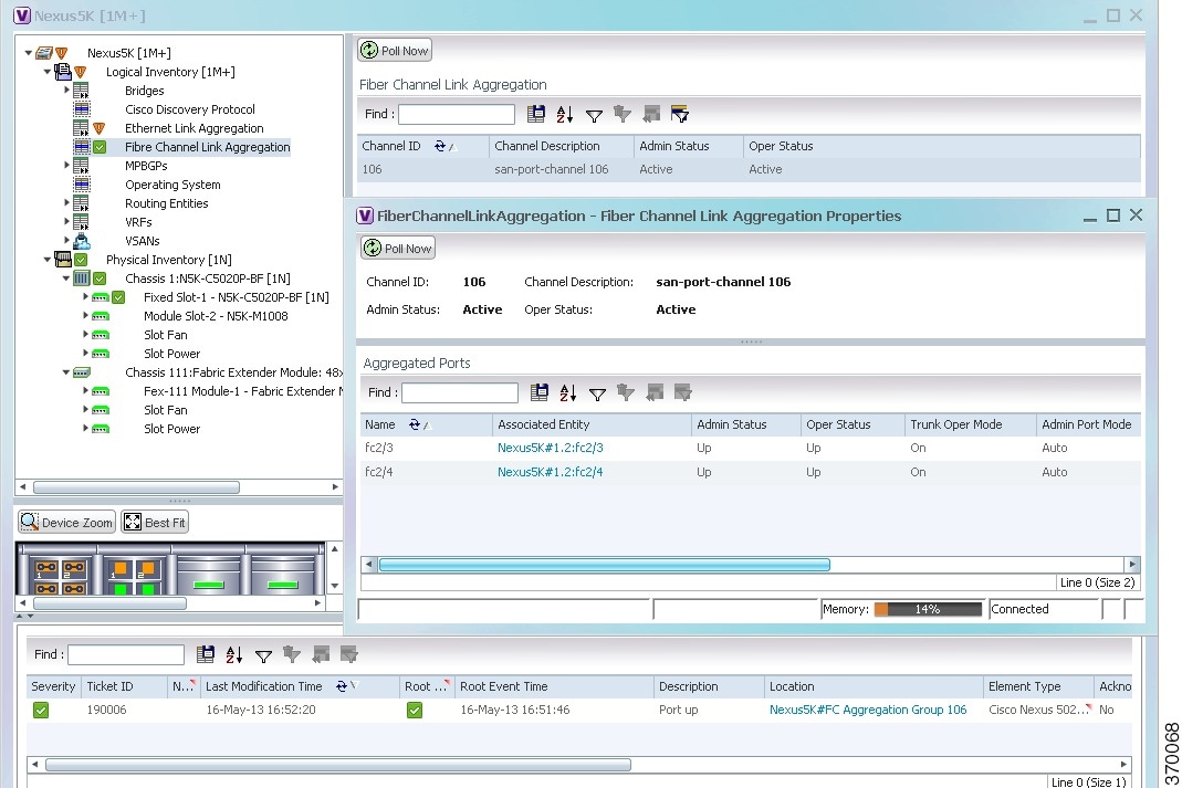
Table 28-13 describes the Fibre Channel Link Aggregation Properties.
|
|
|
|---|---|
The associated port, which when clicked will take you to the relevant FC or FCoE port. |
|
The number of VSANs that are active and allowed to receive data. |
|
Viewing Fibre Channel Links Between Devices in a Map
To view the FC links between devices in a map:
Step 1![]() In the Vision client, open the map that contains the Fibre Channel links.
In the Vision client, open the map that contains the Fibre Channel links.
Step 2![]() Click on the Filter icon in the navigation menu and select only the Fibre Channel check box. Click OK. The map that you have opened only displays the Fibre Channel links between devices. For more information about viewing these link properties, see Viewing the Map Node for an UCS Network Element.
Click on the Filter icon in the navigation menu and select only the Fibre Channel check box. Click OK. The map that you have opened only displays the Fibre Channel links between devices. For more information about viewing these link properties, see Viewing the Map Node for an UCS Network Element.
Searching for Compute Services
The Compute Services Search feature in Prime Network allows you to search for the following entities:
- Virtual Machines (can be found in the VCenter device)
- Hypervisors (can be found in the VCenter device)
- Bare Metal (For example, the blade servers, which can be found in a UCS device)
To use the Compute services search feature:
Step 1![]() In the Vision client, select Network Inventory > Compute Services.
In the Vision client, select Network Inventory > Compute Services.
Step 2![]() In the Compute Services window, select the Search radio button.
In the Compute Services window, select the Search radio button.
Step 3![]() From the Search drop down box, select any one of the following options:
From the Search drop down box, select any one of the following options:
Step 4![]() In the text box available, enter the name based on the option selected in the Search drop-down box.
In the text box available, enter the name based on the option selected in the Search drop-down box.
Step 5![]() Click Go. The entity details are displayed in the table below as shown in Figure 28-18.
Click Go. The entity details are displayed in the table below as shown in Figure 28-18.
Figure 28-18 Compute Service Search
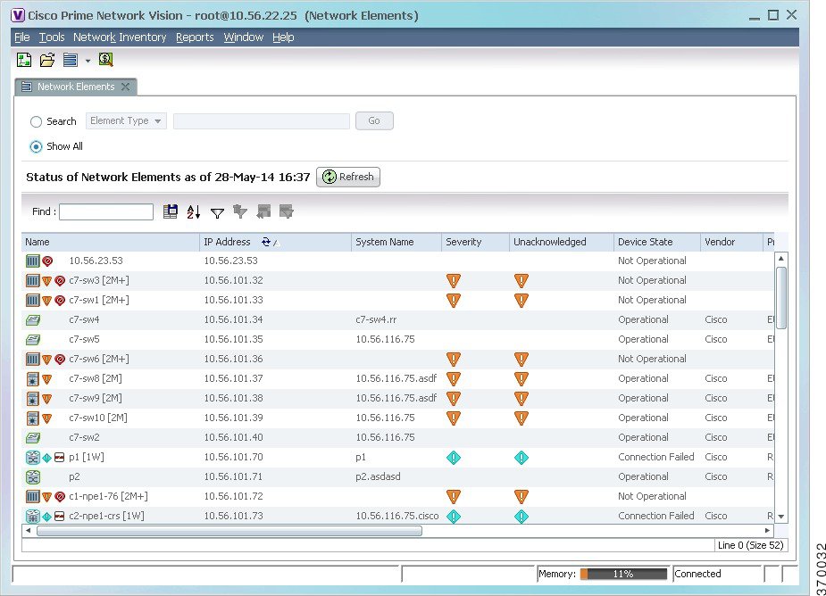
Note![]() You can also click the Show All radio button to view a list of devices with hypervisors, blade servers, and virtual machines.
You can also click the Show All radio button to view a list of devices with hypervisors, blade servers, and virtual machines.
Table 28-14 describes the compute services search results.
Monitoring Virtualized Service Module
Virtualized Service Module (VSM)
The Cisco ASR 9000 VSM Card is a service card built specifically for the Cisco ASR9000 platform. The Cisco ASR 9000 VSM Card is supported on any slot on the Cisco ASR 9000 Series Aggregation Services Router (ASR90xx and ASR99xx). The Cisco ASR 9000 VSM Card has the capability to run a hypervisor on it. The hypervisor (example KVM) can host a single VM.
Service Enablement
Service Enablement provides the ability to install and uninstall a service without impacting the other services running on the Cisco ASR 9000 VSM Card. Service enablement allows you to instantiate a service instance by specifying the name and location of the service image package and the target of the service.
For more information on virtual service package and its installation, refer Configuring Virtual Services on the Cisco ASR 9000 Series Router.
Viewing VSM Properties in Physical Inventory
To view VSM properties in the physical inventory:
Step 1![]() In the Vision client, double-click the device in which the VSM card is configured.
In the Vision client, double-click the device in which the VSM card is configured.
Step 2![]() In the inventory window, expand the Physical Inventory node.
In the inventory window, expand the Physical Inventory node.
Step 3![]() Choose Chassis > Server <Number>: Card A9K-VSM-500. The server configuration details are displayed in the content pane.
Choose Chassis > Server <Number>: Card A9K-VSM-500. The server configuration details are displayed in the content pane.
Table 28-15 describes configuration details of the server configured with ASR 9000 series VSM service information.
Step 4![]() Choose Server <Number>: Card A9K-VSM-500 > Subslot <Number>: Subcard – A9K-MODULEv. The slot details configured with VSM card is displayed in the content pane.
Choose Server <Number>: Card A9K-VSM-500 > Subslot <Number>: Subcard – A9K-MODULEv. The slot details configured with VSM card is displayed in the content pane.
Table 28-16 describes slot configuration details with ASR 9000 series VSM service information.
Step 5![]() Choose Server No: Card A9K-VSM-500 > Subslot <Number>: Subcard – A9K-MODULEv > Interface Name. The port details configured with VSM card is displayed in the content pane.
Choose Server No: Card A9K-VSM-500 > Subslot <Number>: Subcard – A9K-MODULEv > Interface Name. The port details configured with VSM card is displayed in the content pane.
You can view the information displayed for the interface in the physical inventory.
The following information is displayed, depending on the interface and its configuration:
Viewing VSM Properties in Logical Inventory
To view VSM properties in the logical inventory:
Step 1![]() In the Vision client, double-click the device in which the VSM card is configured.
In the Vision client, double-click the device in which the VSM card is configured.
Step 2![]() In the inventory window, expand the Logical Inventory node.
In the inventory window, expand the Logical Inventory node.
Step 3![]() Choose Compute Virtualization> Virtual DataCenter - Default > Host Servers > Host server (KVM). The configuration details of KVM host server are displayed in the content pane.
Choose Compute Virtualization> Virtual DataCenter - Default > Host Servers > Host server (KVM). The configuration details of KVM host server are displayed in the content pane.
Table 28-17 describes KVM host configuration details.
Step 4![]() Choose Compute Virtualization > Virtual DataCenter - Default > Host Servers > Host server (KVM) > WSG. The configuration details of virtual service gateway such as Wireless Security Gateway (WSG) are displayed in the content pane.
Choose Compute Virtualization > Virtual DataCenter - Default > Host Servers > Host server (KVM) > WSG. The configuration details of virtual service gateway such as Wireless Security Gateway (WSG) are displayed in the content pane.
Table 28-18 describes virtual service gateway configuration details.
Step 5![]() Choose Compute Virtualization> Virtual Machines (All Datacenters). The virtual machine details are displayed in the content pane.
Choose Compute Virtualization> Virtual Machines (All Datacenters). The virtual machine details are displayed in the content pane.
 Feedback