- Overview of Prime Network GUI clients
- Setting Up the Prime Network Clients
- Setting Up Change and Configuration Management
- Setting Up Vision Client Maps
- Setting Up Native Reports
- Setting Up Fault Management and the Events Client Default Settings
- Viewing Devices, Links, and Services in Maps
- Drilling Down into an NE’s Physical and Logical Inventories and Changing Basic NE Properties
- Manage Device Configurations and Software Images
- How Prime Network Handles Incoming Events
- Managing Tickets with the Vision Client
- Viewing All Event Types in Prime Network
- Cisco Path Tracer
- Managing IP Address Pools
- Monitoring AAA Configurations
- Managing DWDM Networks
- Managing MPLS Networks
- Managing Carrier Ethernet Configurations
- Managing Ethernet Networks Using Operations, Administration, and Maintenance Tools
- Monitoring Carrier Grade NAT Configurations
- Monitoring Quality of Service
- Managing IP Service Level Agreement (IP SLA) Configurations
- Monitoring IP and MPLS Multicast Configurations
- Managing Session Border Controllers
- Monitoring BNG Configurations
- Managing Mobile Transport Over Pseudowire (MToP) Networks
- Managing Mobile Networks
- Managing Data Center Networks
- Monitoring Cable Technologies
- Monitoring ADSL2+ and VDSL2 Technologies
- Monitoring Quantum Virtualized Packet Core
- VSS Redundancy System
- Icon Reference
- Permissions Required to Perform Tasks Using the Prime Network Clients
- Correlation Examples
- Managing certificates
Monitoring Cable Technologies
Cable broadband communication operates in compliance with the Data Over Cable Service Interface Specification (DOCSIS) standard which prescribes multivendor interoperability and promotes a retail model for the consumer's direct purchase of a cable modem (CM) of choice. Figure 29-1 depicts the architecture of the cable broadband in compliance with this standard:
Figure 29-1 Cable Broadband Architecture
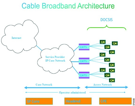
DOCSIS defines two key devices necessary for broadband cable communication:
- Cable Modem Termination System (CMTS) is a piece of equipment typically located in a cable company's headend or hubsite, and used to provide high speed data services, such as cable Internet or voice over Internet Protocol, to cable subscribers. A CMTS provides many of the same functions provided by the DSLAM in a DSL system. In order to provide these high speed data services, a cable company will connect its headend to the Internet via very high capacity data links to a network service provider. On the subscriber side of the headend, the CMTS enables the communication with subscribers' cable modems. A single CMTS can accommodate thousands of cable modems, and provides the connection point to the Internet backbone.
- Cable Modem (CM) is a type of network bridge and modem that provides bi-directional data communication via radio frequency channels on a hybrid fiber-coaxial (HFC) and RFoG infrastructure. Cable modems are primarily used to deliver broadband Internet access in the form of cable Internet, taking advantage of the high bandwidth of a HFC and RFoG network. Usually located at the customer premises, terminates the cable line, and modulates/demodulates signals to and from the CMTS.
Data flowing from the CMTS to the Cable Modem is deemed downstream traffic. Data from the Cable Modem to the CMTS is upstream traffic. A DOCSIS binary configuration file provides the appropriate ISP parameters for cable modems to connect to the network.
There are two types of CMTS systems, which are explained below:
- Integrated CMTS (I-CMTS)—In this type of CMTS, the contents of the downstream channel are directly modulated and transmitted by the Downstream RF Port.
- Modular CMTS (M-CMTS)—In this type of CMTS, the contents of the downstream channel are encapsulated into a DEPI tunnel for transmission.
Cisco Systems offers a complete portfolio of standards-based cable products, solutions, and network management systems that enable integration of data, voice, and video services on a single multiservice cable IP network. For information on supported CMTS systems, refer to Cisco Prime Network 5.0 Supported VNEs.
These topics describe how to use the Vision client to manage cable networks. If you cannot perform an operation that is described in these topics, you may not have sufficient permissions; see Permissions for Managing Cable Technologies.
Viewing the Cable Broadband Configuration Details
You can view the following Cable technology configurations:
- DTI Client—The DOCSIS Timing Interface (DTI) client collects DTI server master clock, DOCSIS timestamp, and Time of Day information from the DTI Server. It interfaces with the DTI Server to provide Time, Frequency and Management interfaces to the Modular Cable Modem Termination System (M-CMTS) device.
- QAM Domain—Quadrature Amplitude Modulation (QAM) domain
- MAC Domain—A MAC domain is a logical subcomponent of a Cisco CMTS router and is responsible for implementing all DOCSIS functions on a set of downstream and upstream channels. The CMTS MAC domain typically includes one or more downstream paths and one or more upstream paths. Depending on the CMTS configuration, the CMTS MAC domain can be defined to have its downstream on one cable interface line card with its upstreams on another card, or one or more CMTS MAC domains per cable interface line card.
- Narrowband Channels—A Narrowband Channel is a logical representation of a non-bonded channel that is a standard DOCSIS 1.x/2.0 protocol downstream channel that contains one RF channel. The wideband protocol utilizes the existing narrowband downstream channel for carrying the MAC management and signaling messages and the associated narrowband upstream for return data traffic and signaling.
- Wideband Channels—A Wideband Channel or Bonded Group (BG) is a logical grouping of one or more physical RF channels over which MPEG-TS packets are carried. Wideband channel carries DOCSIS bonded packets encapsulated in MPEG-TS packets from a WCMTS to one or more WCMs. The wideband channel, comprising of one or more RF channels on the EQAM device, is used for DS data traffic. The US channels on interface line cards—such as the Cisco uBR-MC3GX60V or Cisco uBR10-MC5X20—are used for US traffic.
- Fiber Node—A Fiber Node allows the Multiple Server Operator (MSO) or service provider to configure the CMTS to be more intelligent by making Cisco IOS aware of how the cable plant is wired. The downstream channels of the cable plant must be accurately configured in the CMTS fiber nodes. This allows the CMTS to accurately signal the wideband modems on which the wideband channels are available to the modem.
Viewing the DTI Client Configuration Details
To view the DTI Client configuration details:
Step 1![]() Right-click the required device in the Vision client and choose Inventory.
Right-click the required device in the Vision client and choose Inventory.
Step 2![]() In the logical inventory window, choose Logical Inventory > DTI Client. The DTI Client details are displayed in the content pane.
In the logical inventory window, choose Logical Inventory > DTI Client. The DTI Client details are displayed in the content pane.
Table 29-1 describes the DTI Client configuration details.

Viewing the QAM Domain Configuration Details
To view the QAM domain configuration details:
Step 1![]() Right-click the required device in the Vision client and choose Inventory.
Right-click the required device in the Vision client and choose Inventory.
Step 2![]() In the logical inventory window, choose Logical Inventory > QAM Domain > QAM Domain name. The QAM Domain details are displayed north content pane.
In the logical inventory window, choose Logical Inventory > QAM Domain > QAM Domain name. The QAM Domain details are displayed north content pane.
Table 29-2 describes the QAM Domain configuration details.
|
|
|
|---|---|
The starting port in the range of UDP ports for the video route. |
|
The ending port in the range of UDP ports for the video route. |
|
Viewing the MAC Domain Configuration Details
To view the MAC domain configuration details:
Step 1![]() Right-click the required device in the Vision client and choose Inventory.
Right-click the required device in the Vision client and choose Inventory.
Step 2![]() In the logical inventory window, choose Logical Inventory > MAC Domains > MAC Domain name. The MAC Domain configuration details are displayed in the content pane.
In the logical inventory window, choose Logical Inventory > MAC Domains > MAC Domain name. The MAC Domain configuration details are displayed in the content pane.
Table 29-3 describes the MAC Domain configuration details.
Viewing the Narrowband Channels Configuration Details
To view the Narrowband channels configuration details:
Step 1![]() Right-click the required device in the Vision client and choose Inventory.
Right-click the required device in the Vision client and choose Inventory.
Step 2![]() In the logical inventory window, choose Logical Inventory > Narrowband Channels > Narrowband channel cable. The Narrowband channels configuration details are displayed in the content pane.
In the logical inventory window, choose Logical Inventory > Narrowband Channels > Narrowband channel cable. The Narrowband channels configuration details are displayed in the content pane.
Table 29-4 describes the Narrowband channels configuration details.
Viewing the Wideband Channels Configuration Details
To view the Wideband channels configuration details:
Step 1![]() Right-click the required device in the Vision client and choose Inventory.
Right-click the required device in the Vision client and choose Inventory.
Step 2![]() In the logical inventory window, choose Logical Inventory > Wideband Channels > Wideband cable. The Wideband channels configuration details are displayed in the content pane.
In the logical inventory window, choose Logical Inventory > Wideband Channels > Wideband cable. The Wideband channels configuration details are displayed in the content pane.
Table 29-5 describes the Wideband channels configuration details.
Viewing the Fiber Node Configuration Details
To view the Fiber Node configuration details:
Step 1![]() Right-click the required device in the Vision client and choose Inventory.
Right-click the required device in the Vision client and choose Inventory.
Step 2![]() In the logical inventory window, choose Logical Inventory > Fiber NOde. The Fiber Node configuration details are displayed in the content pane.
In the logical inventory window, choose Logical Inventory > Fiber NOde. The Fiber Node configuration details are displayed in the content pane.
Table 29-6 describes the Fiber Node configuration details.
Configure Cable Ports and Interfaces
These cable port and interface commands can be launched from the Vision client. Your permissions determine whether you can run these commands (see Permissions for Vision Client NE-Related Operations). To find out if a device supports these commands, see the Cisco Prime Network 5.2 Supported Cisco VNEs.
Configure Cable Ports
Configure Cable Interfaces
View Upstream and Downstream Configuration for Cable
Use the following command to view the cable upstream and downstream configuration. Your permissions determine whether you can run these commands (see Permissions for Vision Client NE-Related Operations). To find out if a device supports these commands, see the Cisco Prime Network 5.2 Supported Cisco VNEs.
Configure and View QAM
The following commands configure the Quadrature Amplitude Modulation (QAM) domain for the RF channel. Your permissions determine whether you can run these commands (see Permissions for Vision Client NE-Related Operations). To find out if a device supports these commands, see the Cisco Prime Network 5.2 Supported Cisco VNEs.
Configure RF and Frequency Profiles
Configure QAM Port and Channel
|
|
|
|
|---|---|---|
Physical Inventory > Chassis > Slot > QAM > Commands > Configuration |
View QAM Configurations
|
|
|
|
|---|---|---|
| Displays cable information configured on the QAM channel and port. |
||
Configure DEPI and L2TP
These commands configure the Downstream External PHY Interface (DEPI) and Layer 2 Tunnel Protocol (L2TP). The table below lists the navigation of each of these commands. Your permissions determine whether you can run these commands (see Permissions for Vision Client NE-Related Operations). To find out if a device supports these commands, see the Cisco Prime Network 5.2 Supported Cisco VNEs.
Configure DEPI Class and Tunnel
|
|
|
|
|---|---|---|
| Configures template of DEPI control plane and tunnel configuration settings. |
||
Configure L2TP Class
|
|
|
|
|---|---|---|
| Configures a template of Layer 2 Tunnel Protocol (L2TP) control plane configuration settings. |
||
View DEPI Tunnel, DEPI Session, and L2TP Class
|
|
|
|
|---|---|---|
Displays Layer 2 Tunnel Protocol control plane configuration settings. |
||
Displays DEPI session information and DEPI sessions configured on the line card. |
 Feedback