- Preface
- Product Overview
- Graphical User Interface
- Device and Subdevice Manager
- Users Account Manager
- Configuration and Image Update Jobs Manager
- Groups
- Namespace Manager
- Query Manager
- Data Manager
- Directory Manager
- Parameters Manager
- Templates
- Security Manager
- Log Manager
- Service Manager
- Bulk Data Manager
- Email Manager
- Image Service
- Upgrade or Downgrade Cisco IOS Image
- Backup and Restore
- PIX Firewall Device Support
- ASA Firewall Device Support
- IMGW Device Module Development Kit
- Troubleshooting
- Software Licenses and Acknowledgements
- Index
- Viewing Device Configuration
- Previewing Device Configuration
- Adding Devices
- Discovering Devices
- Editing Devices
- Resynchronizing Devices
- Cloning Devices
- Deleting Devices
- Updating Device Configurations and Images
Device and Subdevice Manager
To access Device tasks, log into the system (see “Logging In” section). Then, from the Home page, click the Devices tab.
Viewing Device Configuration
Step 1![]() From the Devices Functional Overview page, click
View Device
.
From the Devices Functional Overview page, click
View Device
.
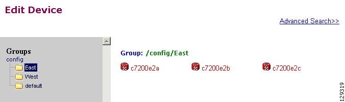
Step 2![]() From the Groups list, select the group that holds the device you want to view.
From the Groups list, select the group that holds the device you want to view.

Note You can also use the Advance Search feature on many GUI pages to locate devices based on user-define search parameters (see “Using Advanced Search Feature” section).
Step 3![]() The View Device list page appears (see Figure 3-1).
The View Device list page appears (see Figure 3-1).
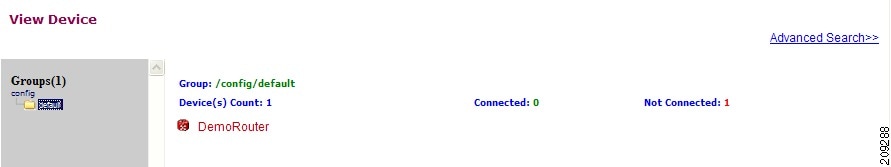
Step 4![]() Click on the icon for the device you want to view.
Click on the icon for the device you want to view.
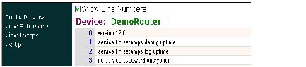
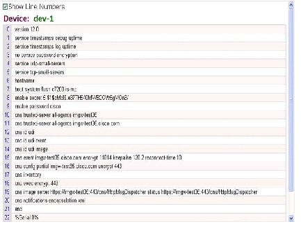
The Configuration for that device appears (see Figure 3-2).
Figure 3-2 Device Configuration

Note The device configuration displayed is the configuration as it appears at the configuration server. It might not be the configuration running on the device.
Step 5![]() To view subdevices (if applicable), in the left navigation pane, click View Subdevices.
To view subdevices (if applicable), in the left navigation pane, click View Subdevices.
Step 6![]() To view Images associated with this device (if applicable), in the left navigation pane, click View Images.
To view Images associated with this device (if applicable), in the left navigation pane, click View Images.
Previewing Device Configuration
Step 1![]() From the Devices Functional Overview page, click Edit Device. The Groups list appears.
From the Devices Functional Overview page, click Edit Device. The Groups list appears.
Step 2![]() From the Groups list, select the group that holds the device in question. The Edit Device list appears.
From the Groups list, select the group that holds the device in question. The Edit Device list appears.
Step 3![]() Form the Edit Device list, select the group that holds the device you want to Preview Device Configuration or
Form the Edit Device list, select the group that holds the device you want to Preview Device Configuration or
Step 4![]() From the Devices Functional Overview page, click View Device. The Groups list appears (see Figure 3-3).
From the Devices Functional Overview page, click View Device. The Groups list appears (see Figure 3-3).
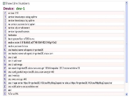
Figure 3-3 Preview Device Configuration
Step 5![]() From the Groups list, select the group that holds the device you want to Preview Device Configuration (see Figure 3-4).
From the Groups list, select the group that holds the device you want to Preview Device Configuration (see Figure 3-4).
Figure 3-4 Device Configuration
Step 6![]() To preview subdevices configuration (if applicable), in the left navigation pane, click View Subdevices.
To preview subdevices configuration (if applicable), in the left navigation pane, click View Subdevices.
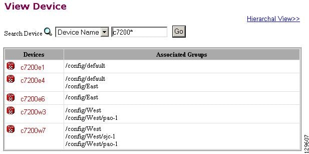
Using Advanced Search Feature
Step 1![]() From the Hierarchal View of groups (for example, see Figure 3-1), click
Advanced Search
.
From the Hierarchal View of groups (for example, see Figure 3-1), click
Advanced Search
.
Step 2![]() Use the drop-down arrow to select:
Config ID
,
Event ID
, or
Device Name
for the desired device.
Use the drop-down arrow to select:
Config ID
,
Event ID
, or
Device Name
for the desired device.
Step 3![]() Then enter a value that corresponds to the first part of the argument, then click
Go
.
Then enter a value that corresponds to the first part of the argument, then click
Go
.
The results of the search are listed (see Figure 3-5).
Figure 3-5 Advanced Search Page
Adding Devices
There are three variations to the Add Device procedures based on Device Type :
- Non-Agent Enabled Device (see below).
- Agent Enabled Device (see “Adding Agent Enabled Devices” section).
- PIX Firewall Device (see “Adding PIX Firewall Devices” section).
- ASA Firewall Device (see “Adding ASA Firewall Devices” section).
Adding Non-agent Enabled Devices
Step 1![]() From the Devices Functional Overview page, click
Add Device
.
From the Devices Functional Overview page, click
Add Device
.
The Device Information page appears (see Figure 3-6).
Figure 3-6 Device Information Page
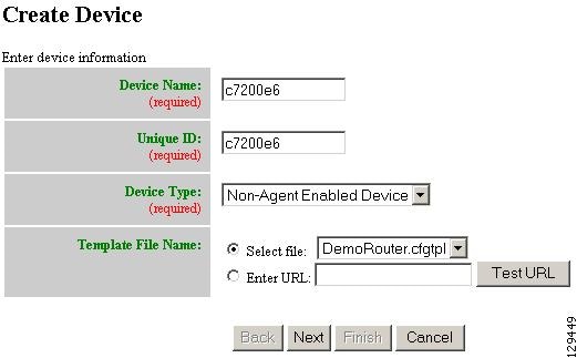
Step 2![]() Enter a valid value (no spaces) in the
Device Name
field.
Enter a valid value (no spaces) in the
Device Name
field.
Table 3-1 shows valid values for these attributes.
Default or |
||
Name of the configuration template to associate with the device. |
Step 3![]() In the
Unique ID
field, accept the default value that appears or enter another valid value (no spaces).
In the
Unique ID
field, accept the default value that appears or enter another valid value (no spaces).
Step 4![]() For Device Type, from the drop-down list, select
Non-Agent Enabled Device
.
For Device Type, from the drop-down list, select
Non-Agent Enabled Device
.
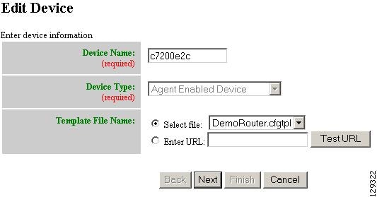
Step 5![]() Select the Template file name, then click
Next
.
Select the Template file name, then click
Next
.
The Group Membership page appears (see Figure 3-7).
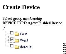

Tip Use the Group Manager to set up groups before you add a device (see “Creating Groups” section).
Step 6![]() Check to select the group(s) of which you want this device to become a member, then click
Next
.
Check to select the group(s) of which you want this device to become a member, then click
Next
.
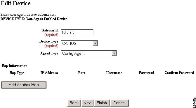
The non-agent information (IMGW) page appears (see Figure 3-8).
Figure 3-8 Non-agent (IMGW) Information Page
Step 7![]() Enter the name of the device in the
Device Name
field.
Enter the name of the device in the
Device Name
field.
Table 3-2 lists valid values for these fields.
Gateway identifier for this device.
This value is established during
Setup
. |
||
Step 8![]() Enter the gateway ID in the
Gateway Id
field.
Enter the gateway ID in the
Gateway Id
field.
Note This value is established during Setup. See Cisco Configuration Engine Installation and Configuration Guide.
Step 9![]() Enter the appropriate Device and Hop information.
Enter the appropriate Device and Hop information.
Tip Before you enter Hop information, see “Hop Tables” section.
Table 3-3 shows valid values for these fields.
Step 10![]() To add another hop, click
Add Another Hop
, then enter hop information.
To add another hop, click
Add Another Hop
, then enter hop information.
Step 11![]() To go back one page, click
Back
.
To go back one page, click
Back
.
Step 12![]() To end this task, click
Finish
.
To end this task, click
Finish
.
Step 13![]() To continue, click
Next
.
To continue, click
Next
.
Step 14![]() To go back one page, click
Back
.
To go back one page, click
Back
.
Step 15![]() To end this task, click
Finish
.
To end this task, click
Finish
.
Step 16![]() To continue, click
Next
.
To continue, click
Next
.
If you click Next , the Image Association page appears (see Figure 3-10).
Figure 3-10 Create Device > Image Association
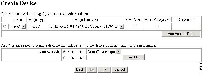
Step 17![]() Select the image from the Name drop-down list.
Select the image from the Name drop-down list.
The Image Type field and Image Location drop-down box are populated with corresponding information for the image.
Step 18![]() From the Image Location drop-down list, select the desired location.
From the Image Location drop-down list, select the desired location.
Step 19![]() To add another row for image location, click Add Another Row.
To add another row for image location, click Add Another Row.
You can locate multiple copies of an image on separate servers. This allows you to do load-sharing when updating a large number of devices. Each device in a large group can be associated with a copy of the image located at one of many server locations.
Step 20![]() In the Destination field, enter a valid URL where the image will be copied.
In the Destination field, enter a valid URL where the image will be copied.
Step 21![]() To indicate which image is to be activated on the device after distribution, select the radio button in front of each row.
To indicate which image is to be activated on the device after distribution, select the radio button in front of each row.
Step 22![]() Select the Configuration Control template file you want to send to this device for activation of a new image:
Select the Configuration Control template file you want to send to this device for activation of a new image:
Tip Use the Configuration Control template that contains the CLI commands required for image activation for this device (see “Configuration Control Templates” section). If you do not have such a template, see “Adding a Template” section.
a.![]() To select a template file from the drop-down list
, click the Select file radio button
.
To select a template file from the drop-down list
, click the Select file radio button
.
b.![]() Use the drop-down list to choose a template file.
Use the drop-down list to choose a template file.
b.![]() Enter the full URL for the server, directory, and filename where the template is stored. Currently, only
http
is supported.
Enter the full URL for the server, directory, and filename where the template is stored. Currently, only
http
is supported.
c.![]() To test access to the external template, click
Test URL
.
To test access to the external template, click
Test URL
.
If the server is unavailable or the external template cannot be accessed, an error appears. You can still save this logical device, but the template is not available until you have access to the external template.
Step 23![]() To clear this task, click
Cancel
.
To clear this task, click
Cancel
.
Step 24![]() To go back to the previous page, click Back.
To go back to the previous page, click Back.
Step 25![]() To finish creating this device, click
Finish
.
To finish creating this device, click
Finish
.
Hop Tables
To access devices by means of Telnet, it is necessary to construct hop tables (see “HopInfo Examples” section). These are tables that indicate what network path exists to the device, and all the authentication information necessary at each stage, or hop.
What You Should Know About Device Hop Information
The Hop Information (HopInfo) structure describes one portion of the path between source and destination. HopInfo can be chained together to specify how to login to a device. Examples of uses of this structure include:
- Devices with basic authentication mode requiring IP address, username, and password
- Devices with additional authentication modes such as Cisco IOS enable mode
- Embedded-within-embedded applications such as line cards on a Catalyst switch
The latter two examples require a login, but not a hop to a different device. Therefore, they are referred to as virtual hops.
Table 3-4 shows the fields in the HopInfo structure:
Currently Supported Device Types
Table 3-5 through Table 3-12 provide the HopInfo list for devices that are directly accessible on the network by IMGW. For accessing devices by way of Commserver, see Table 3-13.
All the rows in these tables are mandatory. Also, the hop_type fields cannot be NULL or empty. The fields marked with X are mandatory in IMGW unless they are not required on the device-side.
When any of the above devices is accessed by way of a Commserver (such as a Cisco 2511 Access Server), the resultant HopInfo list has the following two rows prepended to the respective HopInfo list for that device:
Note Because the current release does not support port username, the username field of HopInfo structure for COMMSERVER is always ignored by IMGW. Do not set up the port username on the Commserver.
Adding Agent Enabled Devices
Step 1![]() From the Devices Functional Overview page, click
Add Device
.
From the Devices Functional Overview page, click
Add Device
.
The Device Information page appears (see Figure 3-11).
Figure 3-11 Device Information Page
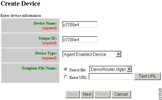
Step 2![]() Enter a valid value (no spaces) in the
Device Name
field.
Enter a valid value (no spaces) in the
Device Name
field.
Table 3-19 shows valid values for these attributes.
Step 3![]() In the
Unique ID
field, accept the default value that appears or enter another valid value (no spaces).
In the
Unique ID
field, accept the default value that appears or enter another valid value (no spaces).
Step 4![]() For Device Type, from the drop-down list, select
Agent Enabled Device
.
For Device Type, from the drop-down list, select
Agent Enabled Device
.
Step 5![]() Select the Template file name, then click
Next
.
Select the Template file name, then click
Next
.
Note To associate an external template to this device, select Enter URL with the appropriate path.
The Group Membership page appears (see Figure 3-12).
Figure 3-12 Group Membership Page
Tip Use the Group Manager to set up groups before you add a device (see “Creating Groups” section).
Step 6![]() Check to select the group(s) of which you want this device to become a member, then click
Next
.
Check to select the group(s) of which you want this device to become a member, then click
Next
.
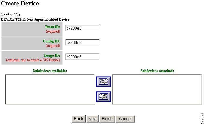
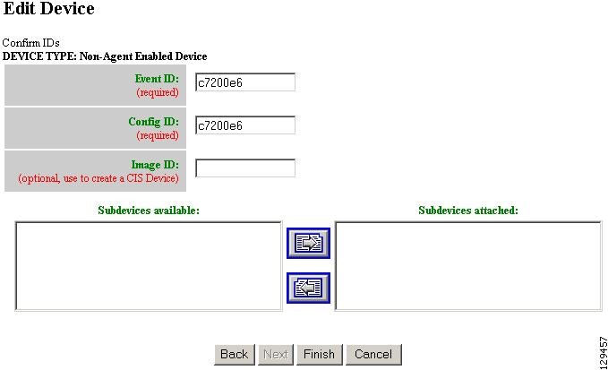
The device IDs page appears (see Figure 3-13).
Step 7![]() Enter the appropriate IDs.
Enter the appropriate IDs.
Table 3-20 shows valid values for these attributes.
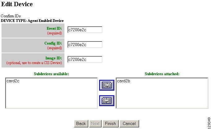
Step 8![]() If applicable, select and assign subdevices to this device.
If applicable, select and assign subdevices to this device.
Step 9![]() To go back one page, click
Back
.
To go back one page, click
Back
.
Step 10![]() To end this task, click
Finish
.
To end this task, click
Finish
.
Step 11![]() To continue by associating this device with an image, click
Next
.
To continue by associating this device with an image, click
Next
.
If you click Next , the Image Association page appears (see Figure 3-14).
Figure 3-14 Create Device > Image Association
Step 12![]() Select the image from the Name drop-down list.
Select the image from the Name drop-down list.
The Image Type field and Image Location drop-down box are populated with corresponding information for the image.
Step 13![]() From the Image Location drop-down list, select the desired location.
From the Image Location drop-down list, select the desired location.
Step 14![]() To add another row for image location, click Add Another Row.
To add another row for image location, click Add Another Row.
You can locate multiple copies of an image on separate servers. This allows you to do load-sharing when updating a large number of devices. Each device in a large group can be associated with a copy of the image located at one of many server locations.
Step 15![]() In the Destination field, enter a valid URL where the image will be copied.
In the Destination field, enter a valid URL where the image will be copied.
Step 16![]() To indicate which image is to be activated on the device after distribution, select the radio button in front of each row.
To indicate which image is to be activated on the device after distribution, select the radio button in front of each row.
Step 17![]() Select the Configuration Control template file you want to send to this device for activation of a new image:
Select the Configuration Control template file you want to send to this device for activation of a new image:
Tip Use the Configuration Control template that contains the CLI commands required for image activation for this device (see “Configuration Control Templates” section). If you do not have such a template, see “Adding a Template” section.
a.![]() To select a template file from the drop-down list
, click the Select file radio button
.
To select a template file from the drop-down list
, click the Select file radio button
.
b.![]() Use the drop-down list to choose a template file.
Use the drop-down list to choose a template file.
b.![]() Enter the full URL for the server, directory, and filename where the template is stored. Currently, only
http
is supported.
Enter the full URL for the server, directory, and filename where the template is stored. Currently, only
http
is supported.
c.![]() To test access to the external template, click
Test URL
.
To test access to the external template, click
Test URL
.
If the server is unavailable or the external template cannot be accessed, an error appears. You can still save this logical device, but the template is not available until you have access to the external template.
Step 18![]() To clear this task, click
Cancel
.
To clear this task, click
Cancel
.
Step 19![]() To go back to the previous page, click Back.
To go back to the previous page, click Back.
Step 20![]() To finish creating this device, click
Finish
.
To finish creating this device, click
Finish
.
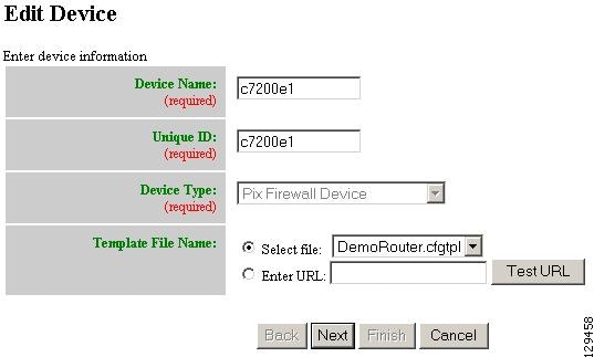
Adding PIX Firewall Devices
Step 1![]() From the Devices Functional Overview page, click
Add Device
.
From the Devices Functional Overview page, click
Add Device
.
The Device Information page appears (see Figure 3-15).
Figure 3-15 Device Information Page
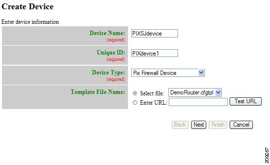
Step 2![]() Enter a valid value (no spaces) in the
Device Name
field.
Enter a valid value (no spaces) in the
Device Name
field.
Table 3-21 shows valid values for these attributes.
Step 3![]() In the
Unique ID
field, accept the default value that appears or enter another valid value (no spaces).
In the
Unique ID
field, accept the default value that appears or enter another valid value (no spaces).
Step 4![]() For Device Type, from the drop-down list, select
PIX Firewall Device
.
For Device Type, from the drop-down list, select
PIX Firewall Device
.
Step 5![]() Select the Template file name, then click
Next
.
Select the Template file name, then click
Next
.
The Group Membership page appears (see Figure 3-16).
Figure 3-16 Group Membership Page
Tip Use the Group Manager to set up groups before you add a device (see “Creating Groups” section).
Step 6![]() Check to select the group(s) of which you want this device to become a member, then click
Next
.
Check to select the group(s) of which you want this device to become a member, then click
Next
.
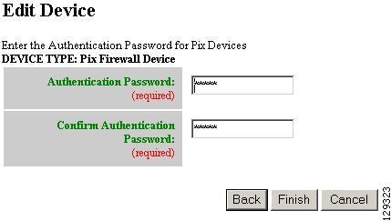
The PixAuthentication Password page appears (see Figure 3-17).
Figure 3-17 PIX Authentication Password Page
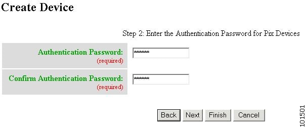
Step 7![]() Enter authentication password for PIX devices.
Enter authentication password for PIX devices.
A case-sensitive password of up to 16 alphanumeric and special characters. Any character can be used in the password except a question mark and a space.
Step 8![]() Click the Next button. The PIX Configuration and Error Actions Type page appears (see Figure 3-18).
Click the Next button. The PIX Configuration and Error Actions Type page appears (see Figure 3-18).
Figure 3-18 PIX Configuration and Error Actions Type Page
Step 9![]() From the Configuration and Error Actions Type page, choose the appropriate options (Replace, Merge, Continue, Revert, and Stop).
From the Configuration and Error Actions Type page, choose the appropriate options (Replace, Merge, Continue, Revert, and Stop).
Step 10![]() To go back one page, click
Back
.
To go back one page, click
Back
.
Step 11![]() To end this task, click
Finish
.
To end this task, click
Finish
.
Step 12![]() To continue by associating this device with an image, click
Next
.
To continue by associating this device with an image, click
Next
.
Step 13![]() If you click
Next
, the Image Association page for PIX Firewall Devices appears.
If you click
Next
, the Image Association page for PIX Firewall Devices appears.
Step 14![]() Select the image from the Name drop-down list.
Select the image from the Name drop-down list.
The Image Type field and Image Location drop-down box are populated with corresponding information for the image.
Note Only PIX or PDM images can be associated with a PIX device.
Step 15![]() From the Image Location drop-down list, select the desired location.
From the Image Location drop-down list, select the desired location.
Step 16![]() To add another row for image location, click Add Another Row.
To add another row for image location, click Add Another Row.
Note For PIX devices, you can have only one PIX image and one PDM image.
Step 17![]() To indicate whether the image is to be activated on the device after distribution, check the box in front of each row.
To indicate whether the image is to be activated on the device after distribution, check the box in front of each row.
Step 18![]() To cancel creating a device and return to the Devices main menu, click
Cancel
.
To cancel creating a device and return to the Devices main menu, click
Cancel
.
Step 19![]() To go back to the previous page, click Back.
To go back to the previous page, click Back.
Step 20![]() To finish creating this device, click
Finish
.
To finish creating this device, click
Finish
.
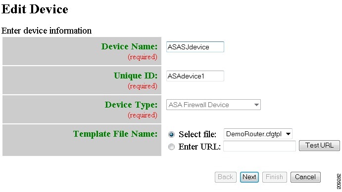
Adding ASA Firewall Devices
Step 1![]() From the Devices Functional Overview page, click
Add Device
.
From the Devices Functional Overview page, click
Add Device
.
The Device Information page appears (see Figure 3-19).
Figure 3-19 Device Information Page
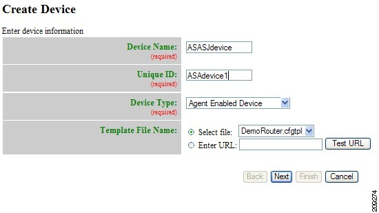
Step 2![]() Enter a valid value (no spaces) in the
Device Name
field.
Enter a valid value (no spaces) in the
Device Name
field.
Table 3-22 shows valid values for these attributes.
Step 3![]() In the
Unique ID
field, accept the default value that appears or enter another valid value (no spaces).
In the
Unique ID
field, accept the default value that appears or enter another valid value (no spaces).
Step 4![]() For Device Type, from the drop-down list, select
ASA Firewall Device
.
For Device Type, from the drop-down list, select
ASA Firewall Device
.
Step 5![]() Select the Template file name, then click
Next
.
Select the Template file name, then click
Next
.
The Group Membership page appears (see Figure 3-20).
Figure 3-20 Group Membership Page
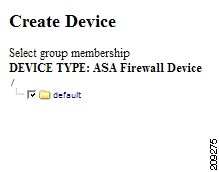
Tip Use the Group Manager to set up groups before you add a device (see “Creating Groups” section).
Step 6![]() Check to select the group(s) of which you want this device to become a member, then click
Next
.
Check to select the group(s) of which you want this device to become a member, then click
Next
.
The ASA Authentication Password page appears (see Figure 3-21).
Figure 3-21 ASA Authentication Password Page
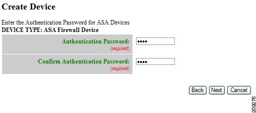
Step 7![]() Enter authentication password for ASA devices.
Enter authentication password for ASA devices.
A case-sensitive password of up to 16 alphanumeric and special characters. Any character can be used in the password except a question mark and a space.
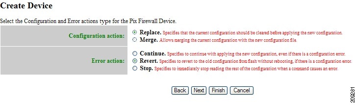
Step 8![]() Click the Next button. The ASA Configuration and Error Actions Type page appears (see Figure 3-17).
Click the Next button. The ASA Configuration and Error Actions Type page appears (see Figure 3-17).
Figure 3-22 ASA Configuration and Error Actions Type Page
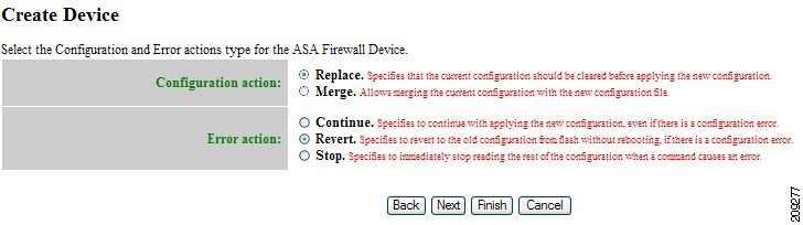
Step 9![]() From the Configuration and Error Actions Type page, choose the appropriate options (Replace, Merge, Continue, Revert, and Stop).
From the Configuration and Error Actions Type page, choose the appropriate options (Replace, Merge, Continue, Revert, and Stop).
Step 10![]() To go back one page, click
Back
.
To go back one page, click
Back
.
Step 11![]() To end this task, click
Finish
.
To end this task, click
Finish
.
Step 12![]() To continue by associating this device with an image, click
Next
.
To continue by associating this device with an image, click
Next
.
Step 13![]() If you click
Next
, the Image Association page for PIX Firewall Devices appears.
If you click
Next
, the Image Association page for PIX Firewall Devices appears.
Step 14![]() Select the image from the Name drop-down list.
Select the image from the Name drop-down list.
The Image Type field and Image Location drop-down box are populated with corresponding information for the image.
Note Only ASA or ASDM images can be associated with a ASA device.
Step 15![]() From the Image Location drop-down list, select the desired location.
From the Image Location drop-down list, select the desired location.
Step 16![]() To add another row for image location, click Add Another Row.
To add another row for image location, click Add Another Row.
Note For ASA devices, you can have only one ASA image and one ASDM image.
Step 17![]() To indicate whether the image is to be activated on the device after distribution, check the box in front of each row.
To indicate whether the image is to be activated on the device after distribution, check the box in front of each row.
Step 18![]() To cancel creating a device and return to the Devices main menu, click
Cancel
.
To cancel creating a device and return to the Devices main menu, click
Cancel
.
Step 19![]() To go back to the previous page, click Back.
To go back to the previous page, click Back.
Step 20![]() To finish creating this device, click
Finish
.
To finish creating this device, click
Finish
.
Discovering Devices
Cisco Configuration Engine can discover a device once the device (for this example: router-3460) is configured for CNS. For more information about this, see CNS Image Agent at:
http://www.cisco.com/en/US/docs/net_mgmt/configuration_engine/3.5/installation/guide/CE_3_ig_security.html
During the execution of setup.sh for the Cisco Configuration Engine host, the settings configured would be:
For detail information about the parameters in this setup, refer to “Cisco Configuration Engine Administration Guide."
Enable cryptographic (crypto) operation between Event Gateway(s)/Config server and device(s) (y/n)? n
Note For more information about running setup.sh, see the Cisco Configuration Engine Installation and Configuration Guide.
Step 2![]() Using the Cisco IOS CLI command:
show running configuration
, verify that
router-3460
is configured with IP routing. For example:
Using the Cisco IOS CLI command:
show running configuration
, verify that
router-3460
is configured with IP routing. For example:
hostname router-3460
...
ip cef
ip host ce_host 10.1.2.3
...
interface Ethernet0/0
ip address 10.1.2.4 255.255.255.0
...
ip default-gateway 10.1.2.1
...
ip classless
ip route 0.0.0.0 0.0.0.0 10.1.2.1
...
ip cef
ip host ce_host 10.1.2.3
...
interface Ethernet0/0
ip address 10.1.2.4 255.255.255.0
...
ip default-gateway 10.1.2.1
...
ip classless
ip route 0.0.0.0 0.0.0.0 10.1.2.1
router-3460 is the hostname identifying the device for Cisco Configuration Engine and 10.1.2.3 is the IP address of the Cisco Configuration Engine.
Step 3![]() Log in to
router-3640
and perform the following operations:
Log in to
router-3640
and perform the following operations:
configure terminal
ip host ce_host 10.1.2.3
cns trusted-server all-agents ce_host
cns id string router-3460
cns id string router-3460 event
cns event ce_host 11013
cns config notify all interval 1 old-format
cns config partial ce_host 80
cns exec 80
Note The above configuration will support Discover Device as well as downloading a configuration, which requires cns config partial ce_host 80.
Step 4![]() Verify IP connectivity between
ce_host
and
router-3640
by issuing the
ping
command from
ce_host
to
router-3640
and from
router-3640
to
ce_host
.
Verify IP connectivity between
ce_host
and
router-3640
by issuing the
ping
command from
ce_host
to
router-3640
and from
router-3640
to
ce_host
.
For our example, name it router-3460 .
You must insert a minimum of one line in the template. You can add a ! for this.
Note For more information about creating a template, see Chapter12, “Templates”
Step 6![]() On the Device Functional Overview page, choose
Discover Device
.
On the Device Functional Overview page, choose
Discover Device
.
Figure 3-23 Discover Device Page
When the discovery task completes, the following information appears:
Device Name DeviceID Connected Time Template Name Group Name
router-3640 router-3640 1/19/06 9:46:03 AM
router-3640 router-3640 1/19/06 9:46:03 AM
Step 7![]() Click on the check box for
router-3640
, then click on the radio button and move the cursor to
router-3640.cfgtpl
.
Click on the check box for
router-3640
, then click on the radio button and move the cursor to
router-3640.cfgtpl
.
The following information appears:
Status of Discovered Device Creation:
Device Name Template Name Status
router-3640 router-3640.cfgtpl Success
Device Name Template Name Status
router-3640 router-3640.cfgtpl Success
Step 9![]() On the Device Functional Overview page, choose
View Device
.
On the Device Functional Overview page, choose
View Device
.
You should see an icon for router-3640 .
The icon color should be green indicating communication between ce_host and router-3640 has been established.
1.![]() Before a device is discovered or created, we recommend that you configure a template for the device. When Cisco Configuration Engine discovers a device, or you create a device, you then must associate the device with a template. Although Cisco Configuration Engine has a default sample template (DemoRouter.cfgtpl) already created, it is very unlikely that your device will be configured using DemoRouter.cfgtpl. Therefore, create a new template.
Before a device is discovered or created, we recommend that you configure a template for the device. When Cisco Configuration Engine discovers a device, or you create a device, you then must associate the device with a template. Although Cisco Configuration Engine has a default sample template (DemoRouter.cfgtpl) already created, it is very unlikely that your device will be configured using DemoRouter.cfgtpl. Therefore, create a new template.
2.![]() If
Create Device
is performed after configuring a template for
router-c3460
, then Cisco Configuration Engine will not discover this router (you will not see an icon for
router-c3460
when Discover Device is selected). If you want Cisco Configuration Engine to discover the device then create only a template for the device—DO NOT use the
Create Device
operation. If you use
Create Device
, and you go to
Discover Device
, you will not see an icon for
router-c3460
. However, in either case,
View Device
should show an icon for
router-c3460
.
If
Create Device
is performed after configuring a template for
router-c3460
, then Cisco Configuration Engine will not discover this router (you will not see an icon for
router-c3460
when Discover Device is selected). If you want Cisco Configuration Engine to discover the device then create only a template for the device—DO NOT use the
Create Device
operation. If you use
Create Device
, and you go to
Discover Device
, you will not see an icon for
router-c3460
. However, in either case,
View Device
should show an icon for
router-c3460
.
3.![]() The Cisco Configuration Engine host uses odd numbered event ports for messages sent in plain text. For example, the default Cisco Configuration Engine setting is 5 event gateway ports without crypto enabled. Devices use ports 11013, 11015, 11017, 11019, 11021 depending on what you configured on the device (for cns event 10.1.2.3 11013 this means event gateway port 11013 is used by router-c3640 to communicate with the Cisco Configuration Engine host, 10.1.2.3).
The Cisco Configuration Engine host uses odd numbered event ports for messages sent in plain text. For example, the default Cisco Configuration Engine setting is 5 event gateway ports without crypto enabled. Devices use ports 11013, 11015, 11017, 11019, 11021 depending on what you configured on the device (for cns event 10.1.2.3 11013 this means event gateway port 11013 is used by router-c3640 to communicate with the Cisco Configuration Engine host, 10.1.2.3).
4.![]() The Cisco Configuration Engine host uses even numbered event ports for message sent encrypted starting with 11014. For example, if you set the number of event gateways to 2 during setup, then ports 11014 and 11016 would be available for use by a device.
The Cisco Configuration Engine host uses even numbered event ports for message sent encrypted starting with 11014. For example, if you set the number of event gateways to 2 during setup, then ports 11014 and 11016 would be available for use by a device.
Note • The ports for Event Gateways with crypto operation are even numbers that start from 11012.
Editing Devices
Step 1![]() From the Devices Functional Overview page, click
Edit Device
.
From the Devices Functional Overview page, click
Edit Device
.
Step 2![]() From the Groups list, select the group that holds the device in question.
From the Groups list, select the group that holds the device in question.
The Edit Device list appears (see Figure 3-24).
Step 3![]() Click on the icon for the device you want to edit. The device configuration appears (see Figure 3-25).
Click on the icon for the device you want to edit. The device configuration appears (see Figure 3-25).
Figure 3-25 Device Configuration
Step 4![]() From the left navigation pane, choose the edit function you want to use.
From the left navigation pane, choose the edit function you want to use.
Editing Non-agent Enabled Device Information
Step 1![]() From the Edit Device page, click
Edit Information
.
From the Edit Device page, click
Edit Information
.
The device information editor page appears (see Figure 3-26).
Figure 3-26 Non-agent Device Information Editor
Step 2![]() To modify the device name, enter a valid value (no spaces) in the
Device Name
field, then click
Next
.
To modify the device name, enter a valid value (no spaces) in the
Device Name
field, then click
Next
.
Step 3![]() Select Group Membership, then click
Next
.
Select Group Membership, then click
Next
.
The Non-agent Edit Device Information page appears (see Figure 3-27).
Figure 3-27 Non-agent Information Page
Step 4![]() Edit all appropriate fields, then to end this task, click
Finish
.
Edit all appropriate fields, then to end this task, click
Finish
.
Step 5![]() To continue, click
Next
.
To continue, click
Next
.
The device IDs page appears (see Figure 3-28).
Figure 3-28 Edit Non-agent Device IDs Page
Step 6![]() Modify devices IDs as required, then click
Finish
.
Modify devices IDs as required, then click
Finish
.
Editing Agent Enabled Device Information
Step 1![]() From the Edit Device page, click
Edit Information
.
From the Edit Device page, click
Edit Information
.
The device information editor page appears (see Figure 3-29).
Figure 3-29 Agent Enabled Device Information Page
Step 2![]() To modify the device name, enter a valid value (no spaces) in the
Device Name
field, then click
Next
.
To modify the device name, enter a valid value (no spaces) in the
Device Name
field, then click
Next
.
Step 3![]() Select Group Membership, then click
Next
.
Select Group Membership, then click
Next
.
The device IDs page appears (see Figure 3-30).
Figure 3-30 Agent enabled Device IDs Page
Step 4![]() Modify device IDs as required, then click
Finish
.
Modify device IDs as required, then click
Finish
.
Editing PIX Device Information
Step 1![]() From the Edit Device page, click
Edit Information
.
From the Edit Device page, click
Edit Information
.
The device information editor page appears (see Figure 3-31).
Figure 3-31 PIX Device Information Page
Step 2![]() To modify the device name and Image ID, if applicable, then click
Next
.
To modify the device name and Image ID, if applicable, then click
Next
.
Step 3![]() Select Group Membership, then click
Next
.
Select Group Membership, then click
Next
.
The PIX Device Authentication Password page appears, see Figure 3-32.
Figure 3-32 PIX Device Authentication Password
Step 4![]() Modify the authentication password if required, then click
Finish
.
Modify the authentication password if required, then click
Finish
.
A case-sensitive password of up to 16 alphanumeric and special characters. Any character can be used in the password except a question mark and a space.
Editing ASA Device Information
Step 1![]() From the Edit Device page, click
Edit Information
.
From the Edit Device page, click
Edit Information
.
The device information editor page appears (see Figure 3-33).
Figure 3-33 ASA Device Information Page
Step 2![]() To modify the device name and Image ID, if applicable, then click
Next
.
To modify the device name and Image ID, if applicable, then click
Next
.
Step 3![]() Select Group Membership, then click
Next
.
Select Group Membership, then click
Next
.
The ASA Device Authentication Password page appears, see Figure 3-34.
Figure 3-34 ASA Device Authentication Password
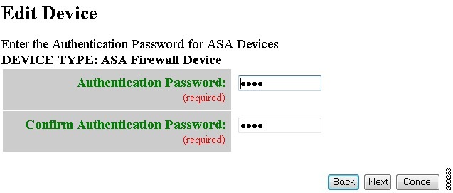
Step 4![]() Modify the authentication password if required, then click
Finish
.
Modify the authentication password if required, then click
Finish
.
A case-sensitive password of up to 16 alphanumeric and special characters. Any character can be used in the password except a question mark and a space.
Editing Device Templates
Step 1![]() From the Edit Device page, click
Edit Template
.
From the Edit Device page, click
Edit Template
.
The template editor appears (see Figure 3-35).
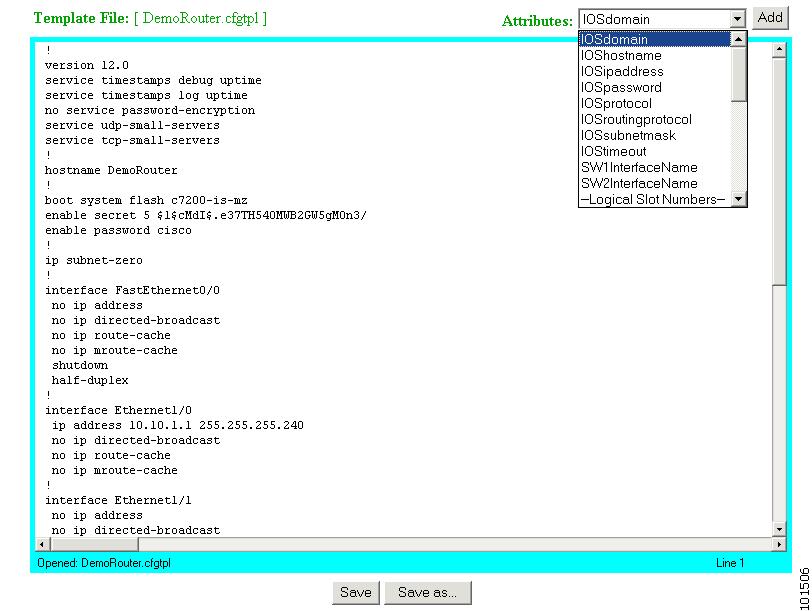
Step 2![]() In the
Attributes
field, click the drop-down arrow.
In the
Attributes
field, click the drop-down arrow.
Step 3![]() Choose the attribute you want to add to the template, then click
Add
.
Choose the attribute you want to add to the template, then click
Add
.
Step 4![]() Repeat Steps 2 and 3 for all attributes you want to add to the template file.
Repeat Steps 2 and 3 for all attributes you want to add to the template file.
Step 5![]() Delete all unusable strings from the template file.
Delete all unusable strings from the template file.
Step 6![]() Edit strings as necessary.
Edit strings as necessary.
The default multi-line begin and end tags are ^C and ^C respectively. The delimiter for these tags are: ~ ! @ ^ & * - = |. Do not use # or %.
For example, a multi-line test banner might be:
Step 7![]() To save your edits, click
Save
.
To save your edits, click
Save
.
Step 8![]() To save this version as a new template, click
Save as
.
To save this version as a new template, click
Save as
.
Editing Device Parameters
Step 1![]() From the Edit Device page:
From the Edit Device page:
a.![]() If you have administrator-level access click
Edit Parameter-admin
.
If you have administrator-level access click
Edit Parameter-admin
.
b.![]() To use Operator-level access click
Edit Parameter-operator
.
To use Operator-level access click
Edit Parameter-operator
.
The parameters editor appears.
Step 2![]() Edit all active lines as required.
Edit all active lines as required.
Step 3![]() To save your edits, click
Save Parameters
.
To save your edits, click
Save Parameters
.
Editing Contact Information
Step 1![]() From the Edit Device page, click
Edit ContactInfo
.
From the Edit Device page, click
Edit ContactInfo
.
The contact information appears.
Step 2![]() Edit all active fields as required.
Edit all active fields as required.
Step 3![]() To clear your entries, click
Reset
.
To clear your entries, click
Reset
.
Step 4![]() To save your edits, click
Update
.
To save your edits, click
Update
.
Editing Subdevices
For complete information about working with subdevices, including editing (except PIX devices), see “Working with Subdevices” section.
Resynchronizing Devices
If the password of a device becomes corrupted so that there is a mismatch between the device and the corresponding password information help in the directory, you can resynchronize the device with the Cisco Configuration Engine by using the Resync Device function.
Step 1![]() From the Devices Functional Overview page, click
Resync Device
.
From the Devices Functional Overview page, click
Resync Device
.
Step 2![]() From the Resync Device page, click on the icon for the device you want to re-synchronize.
From the Resync Device page, click on the icon for the device you want to re-synchronize.
Note PIX devices will not be visible on this page.
Step 3![]() In the confirmation window that appears, click
Ok
.
In the confirmation window that appears, click
Ok
.
Cloning Devices
Step 1![]() From the Devices Functional Overview page, click
Clone Device
.
From the Devices Functional Overview page, click
Clone Device
.
Step 2![]() From the Groups list, select the group that holds the device you want to clone.
From the Groups list, select the group that holds the device you want to clone.
The Clone Device list appears (see Figure 3-36).
Step 3![]() Select a device to clone.
Select a device to clone.
The Step 1 page appears (see Figure 3-37).
Figure 3-37 Clone Device > Number of Copies
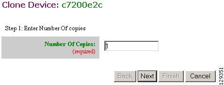
Step 4![]() Determine the number of copies, then click
Next
.
Determine the number of copies, then click
Next
.
The Step 2 page appears (see Figure 3-38).
Figure 3-38 Clone Device > Name and IDs
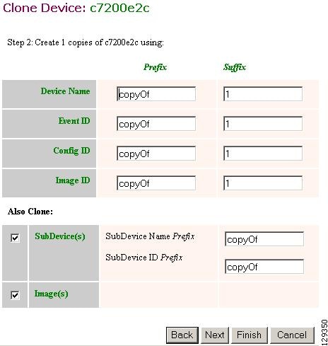
Step 5![]() Enter prefix and suffix for each device copy, then click
Next
.
Enter prefix and suffix for each device copy, then click
Next
.
The Step 3 page appears (see Figure 3-39).
Figure 3-39 Clone Device > Review Parameters
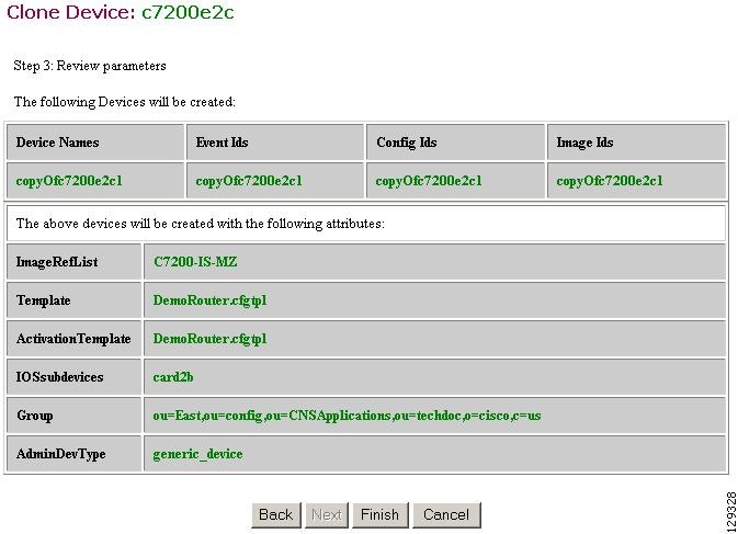
Step 6![]() Review the parameters you set for this clone.
Review the parameters you set for this clone.
Step 7![]() If you want to make changes, click
Back
.
If you want to make changes, click
Back
.
Step 8![]() To finish this task, click
Finish
.
To finish this task, click
Finish
.
Deleting Devices
Step 1![]() From the Devices Functional Overview page, click
Delete Device
.
From the Devices Functional Overview page, click
Delete Device
.
Step 2![]() From the Groups list, select the group that holds the device you want to delete.
From the Groups list, select the group that holds the device you want to delete.
Step 3![]() Click the check box for the device(s) you want to delete.
Click the check box for the device(s) you want to delete.
A list of devices selected for deletion appears.
Step 5![]() To continue, click Delete.
To continue, click Delete.
Updating Device Configurations and Images
To send an updated version of the configuration or a new image to a device, from the Devices Functional Overview page, click Update Device . The Update Device Functional Overview page appears showing:
Updating Device Configurations
Step 1![]() From the Update Devices Functional Overview page, click
Update Config
.
From the Update Devices Functional Overview page, click
Update Config
.
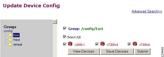
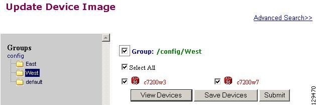
Step 2![]() From the Groups list, select the group that holds the device you want to update.
From the Groups list, select the group that holds the device you want to update.
Step 3![]() Click the check box next to the icon for the device(s) you want to update (see Figure 3-40).
Click the check box next to the icon for the device(s) you want to update (see Figure 3-40).
Figure 3-40 Update Config Group/Device Selection Page
Note PIX devices will not be visible on this page.
The update notification page appears (see Figure 3-41).
Figure 3-41 Update Configuration Notification Information
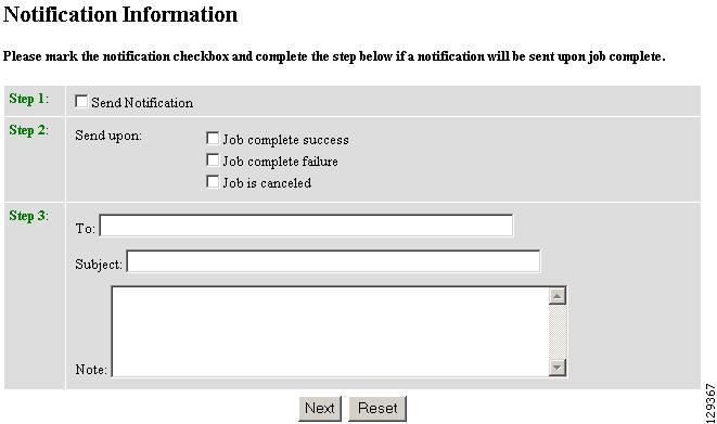
Step 5![]() If you want an email notification sent when the update job completes, fill in the information on this page, then click
Next
.
If you want an email notification sent when the update job completes, fill in the information on this page, then click
Next
.
Note This page is optional. You can skip to the next page by clicking Next.
The update task dialog box appears (see Figure 3-42).
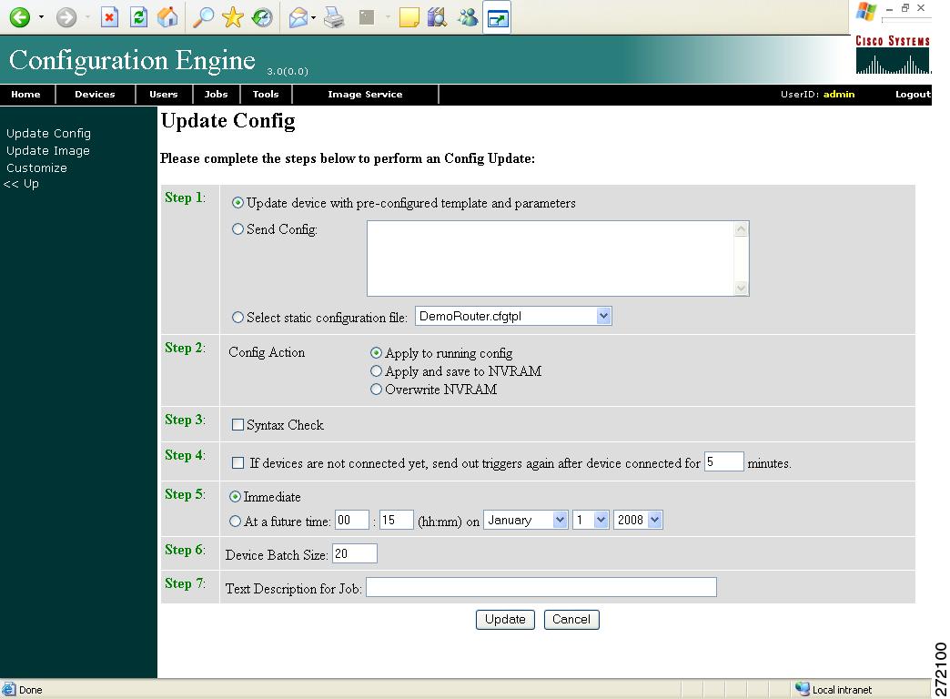
Step 6![]() For Step 1, select the source of the configuration.
For Step 1, select the source of the configuration.
Step 7![]() For Step 2, choose the
Config Action
task you require.
For Step 2, choose the
Config Action
task you require.
- Apply to running config – applies the configuration to the current running configuration.
- Apply and save to NVRAM – applies the configuration without causing it to persist in NVRAM.
- Overwrite NVRAM – applies the change and causes it to persists in NVRAM.
Step 8![]() For Step 3, if required, check the Syntax Check check box.
For Step 3, if required, check the Syntax Check check box.
Step 9![]() For Step 4, if devices are not connected, check this check box to send out triggers.
For Step 4, if devices are not connected, check this check box to send out triggers.
Step 10![]() For Step 5, select the date and time to send the configuration update.
For Step 5, select the date and time to send the configuration update.
Step 11![]() For Step 6, determine the batch size.
For Step 6, determine the batch size.
Tip The max batch size for IMGW should be set at 25.
Step 12![]() For Step 7, if applicable, enter a description for this update job.
For Step 7, if applicable, enter a description for this update job.
Updating Device Images
Step 1![]() From the Update Device Functional Overview page, click Update Image.
From the Update Device Functional Overview page, click Update Image.
Step 2![]() From the Groups list, select the group that holds the device you want to update.
From the Groups list, select the group that holds the device you want to update.
Step 3![]() Click the check box next to the icon for the device(s) you want to update (see Figure 3-43).
Click the check box next to the icon for the device(s) you want to update (see Figure 3-43).
Figure 3-43 Update Image Group/Device Selection Page
Note PIX/ASA devices will not be visible on this page.
The update notification page appears (see Figure 3-41).
Step 5![]() If you want a notification sent when the update job completes, fill in the information on this page, then click
Next
.
If you want a notification sent when the update job completes, fill in the information on this page, then click
Next
.
Note This page is optional. You can skip to the next page by clicking Next.
The Update Image page appears (see Figure 3-44).
Figure 3-44 Image Selection Page
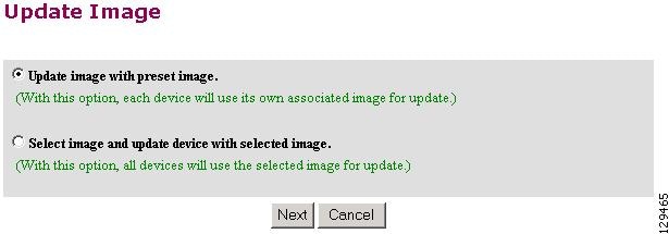
Step 6![]() Select the image you want to use for updates, then click
Next
.
Select the image you want to use for updates, then click
Next
.
If you select to update the device by selecting an image other than its present image, the next page gives you a list of images from which to select.
The Update Image worksheet appears (see Figure 3-45).
Figure 3-45 Update Image Worksheet
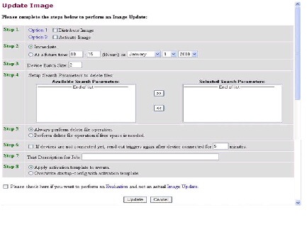
Step 7![]() To distribute the image, click the check box for Distribute Image.
To distribute the image, click the check box for Distribute Image.
Step 8![]() To activate the image, click the check box for Activate Image.
To activate the image, click the check box for Activate Image.
Tip All three agents (event, partial config, and image) must be running on the device for the activation process to succeed.
Note For the image to become active on the device, you must have a Configuration Control template associated with this device that contains the CLI commands for image activation (see “Configuration Control Templates” section).
Step 9![]() To update the image immediately, click the radio button for Immediate.
To update the image immediately, click the radio button for Immediate.
Step 10![]() To update the image at a specified time in the future, click the radio button for At a future time:
To update the image at a specified time in the future, click the radio button for At a future time:
Step 11![]() Set the Device Batch Size.
Set the Device Batch Size.
This is the number of concurrent image updates. This feature allows you to limit the number of concurrent requests to a server. When one batch of image update requests has been satisfied, the next batch starts.
Tip The max batch size for IMGW should be set at 25. And for HTTP only (no event agent) mode, the batch size must be same as the number devices in the submitted job.
Note If you are running a device image update session to a mix of IMGW and agent devices, the effective device batch size limit for IMGW devices—concurrent Telnet session limit—is equal to the value (default = 25) set for this attribute in the Setup program (see Cisco Configuration Engine Installation and Configuration Guide).
Step 12![]() If applicable, enter a text description of the job.
If applicable, enter a text description of the job.
Step 13![]() To perform an evaluation rather than an actual update, click the check box at the bottom of this pane.
To perform an evaluation rather than an actual update, click the check box at the bottom of this pane.
Step 14![]() To continue, complete the steps called for, then click
Update.
To continue, complete the steps called for, then click
Update.
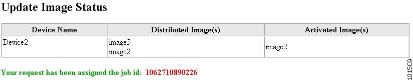
The Update Image Status page appears (see Figure 3-46). You can use this Job ID to perform job-related tasks (see Chapter 5, “Configuration and Image Update Jobs Manager”).
Figure 3-46 Job ID for Update Image
Customize Job Template
Step 1![]() From the Update Device Functional Overview page, click
Customize
.
From the Update Device Functional Overview page, click
Customize
.
Step 2![]() From the Groups list, select the group that holds the device you want to update.
From the Groups list, select the group that holds the device you want to update.
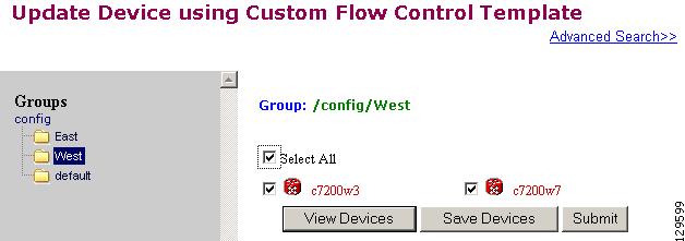
Step 3![]() Click the check box next to the icon for the device(s) you want to update (see Figure 3-47).
Click the check box next to the icon for the device(s) you want to update (see Figure 3-47).
Figure 3-47 Custom Flow Control Device Update Selection Page
Note PIX devices will not be visible on this page.
The Update Device using Customized Job Template appears (see Figure 3-48).
Figure 3-48 Customized Job Template Form
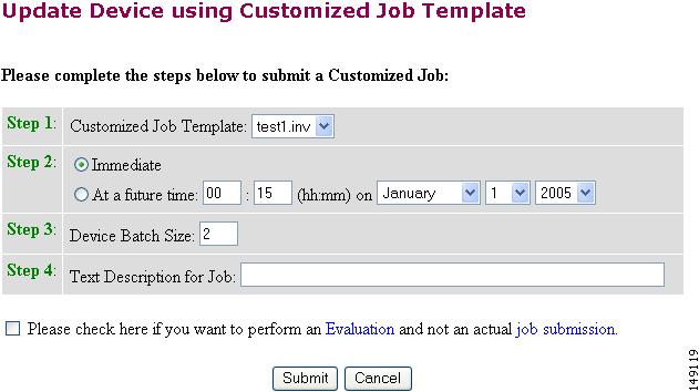
Step 5![]() Complete the Customized Job Template form, then click
Submit
.
Complete the Customized Job Template form, then click
Submit
.
The next page shows the Job ID for this update task.
Step 6![]() To check the status of this job go to
Jobs > Query Jobs
, then click on the Job ID for this Job.
To check the status of this job go to
Jobs > Query Jobs
, then click on the Job ID for this Job.
Configuration Control Template
To restart a device with a new image, you must issue the CLI commands that you would normally enter from the device console to activate a new image.
For example, if you want to restart a Cisco 3600 Series router with an image named 3600.image, from the device console, you would issue the following CLI commands:
no boot system
boot system flash:3600.image
you must provide the device with a Configuration Control template that contains the required CLI commands for image activation.
If you do not have such a template, see “Adding a Template” section. Also, you must associate this Configuration Control template with the particular device (see “Adding Devices” section).
The content of the Configuration Control template for image activation should contain the CLI commands that you would normally enter from the device console to activate a new image on the device.
Working with Subdevices
A subdevice is a configuration object for network modules in a modular router. When working with subdevices, it is very important to pick the correct type of interface card or module.
Note PIX Firewall devices do not have subdevices.
To work with subdevices, from the Devices Functional Overview page, click Subdevices .
The Subdevices Functional Overview page appears showing:
Viewing Subdevices
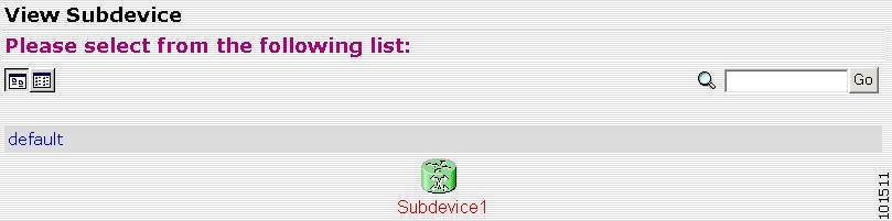
Step 1![]() From the Subdevices Functional Overview page, select
View Subdevice
.
From the Subdevices Functional Overview page, select
View Subdevice
.
The list of subdevices appears (see Figure 3-49).
Step 2![]() Click on the icon for the device configuration you want to view.
Click on the icon for the device configuration you want to view.
The Configuration for that device appears.
Note The subdevice configuration displayed is the configuration as it appears at the configuration server. It might not be the configuration running on the subdevice.
Adding Subdevices
Step 1![]() From the Subdevices Functional Overview page, click
Add Subdevice
.
From the Subdevices Functional Overview page, click
Add Subdevice
.
The Subdevice Information page appears (see Figure 3-50).
Figure 3-50 Subdevice Information Page
Step 2![]() Enter a valid value (no spaces) in the
Device Name
field.
Enter a valid value (no spaces) in the
Device Name
field.
Table 3-23 shows valid values for this task.
Step 3![]() Accept the default value that appears or enter another valid value (no spaces) in the
Config ID
field.
Accept the default value that appears or enter another valid value (no spaces) in the
Config ID
field.
Step 4![]() From the
Device Type
drop-down list, choose the type of device to which this subdevice is associated.
From the
Device Type
drop-down list, choose the type of device to which this subdevice is associated.
Device type is the name of the network module as defined in the Cisco product catalog (price list).
Step 5![]() Choose a template file.
Choose a template file.
To use a template on your Cisco Configuration Engine:
b.![]() Use the drop-down list to choose a template.
Use the drop-down list to choose a template.
b.![]() Enter the full URL for the server, directory, and filename where the template is stored. Currently, only
http
is supported.
Enter the full URL for the server, directory, and filename where the template is stored. Currently, only
http
is supported.
c.![]() To test access to the external template, click
Test URL
.
To test access to the external template, click
Test URL
.
If the server is unavailable or the external template cannot be accessed, an error appears. You can still save this logical subdevice, but the template is not available until you have access to the external template.
Step 6![]() To clear your entries, click
Reset
.
To clear your entries, click
Reset
.
Step 7![]() To add this device, click
Add
.
To add this device, click
Add
.
Editing Subdevices
Step 1![]() From the Subdevices Functional Overview page, click
Edit Subdevice
.
From the Subdevices Functional Overview page, click
Edit Subdevice
.
Step 2![]() From the Edit Subdevice page, click on the icon for the subdevice you want to edit.
From the Edit Subdevice page, click on the icon for the subdevice you want to edit.
The subdevice configuration appears with a menu of edit functions in the left navigation pane:
- Edit Information
- Edit Template
- Edit Parameter-Admin – Administrator-level view
- Edit Parameter-Operator – Operator-level view; used by Administrator to verify what Operator can see after Administrator has used Edit > AttributInfo under the Template Manager
- Edit ContactInfo
Step 3![]() From the left navigation pane, choose the edit function you want to use.
From the left navigation pane, choose the edit function you want to use.
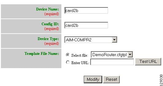
Editing Subdevice Information
Step 1![]() From the Edit Subdevice page, click
Edit Information
.
From the Edit Subdevice page, click
Edit Information
.
The subdevice information editor dialog box appears (see Figure 3-50).
Step 2![]() Modify all applicable fields.
Modify all applicable fields.
For valid values, see Table 3-23 .
Step 3![]() To clear your entries, click
Reset
.
To clear your entries, click
Reset
.
Step 4![]() To update device information, click
Modify
.
To update device information, click
Modify
.
Editing Subdevice Template
Step 1![]() From the Edit Subdevice left navigation pane, click
Edit Template
.
From the Edit Subdevice left navigation pane, click
Edit Template
.
Step 2![]() In the
Attributes
field, click the drop-down arrow.
In the
Attributes
field, click the drop-down arrow.
Step 3![]() Choose the attribute you want to add to the template, then click
Add
.
Choose the attribute you want to add to the template, then click
Add
.
Step 4![]() Repeat Steps 2 and 3 for all attributes you want to add to the template file.
Repeat Steps 2 and 3 for all attributes you want to add to the template file.
Step 5![]() Delete all unusable strings from the template file.
Delete all unusable strings from the template file.
Step 6![]() Edit strings as necessary.
Edit strings as necessary.
The default multi-line begin and end tags are ^C and ^C respectively. The delimiter for these tags are: ~ ! @ ^ & * - = |. Do not use # or %.
A multi-line test banner might be:
Step 7![]() To save your edits, click
Save
.
To save your edits, click
Save
.
Step 8![]() To save this version as a new template, click
Save as
.
To save this version as a new template, click
Save as
.
Editing Subdevice Parameters
Step 1![]() From the Edit Subdevice left navigation pane, click
Edit Parameter-Admin
.
From the Edit Subdevice left navigation pane, click
Edit Parameter-Admin
.
The parameters editor appears.
Note Operator-level privileges do not include access to these parameters.
Step 2![]() Modify parameters values as required.
Modify parameters values as required.
Step 3![]() To save your edits, click
Save Parameters
.
To save your edits, click
Save Parameters
.
Editing Contact Information
Step 1![]() From the Edit Device left navigation pane, click
Edit ContactInfo
.
From the Edit Device left navigation pane, click
Edit ContactInfo
.
The contact information appears.
Step 2![]() Edit all active fields as required.
Edit all active fields as required.
Step 3![]() To clear your entries, click
Reset
.
To clear your entries, click
Reset
.
Step 4![]() To save your edits, click
Update
.
To save your edits, click
Update
.
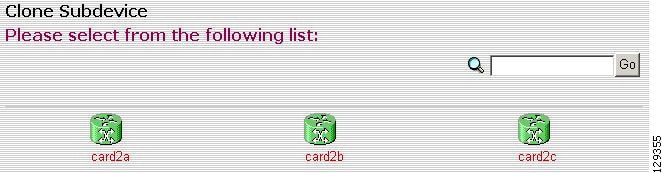
Cloning Subdevices
Step 1![]() From the Subdevices Functional Overview page, click
Clone Subdevice
.
From the Subdevices Functional Overview page, click
Clone Subdevice
.
The Subdevice list appears (see Figure 3-51).
Figure 3-51 Clone Subdevice Device List
Step 2![]() The Step 1 page appears (see Figure 3-52).
The Step 1 page appears (see Figure 3-52).
Figure 3-52 Clone Subdevice > Number of Copies
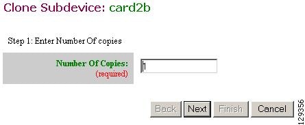
Enter the number of copies you want to make, then click Next .
The Step 2 page appears (see Figure 3-53).
Figure 3-53 Clone Subdevice > Name and IDs
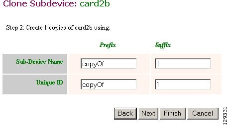
Step 3![]() Enter prefix and suffix for each device copy, click
Next
.
Enter prefix and suffix for each device copy, click
Next
.
The Step 3 page appears (see Figure 3-54).
Figure 3-54 Clone Subdevice > Review Parameters
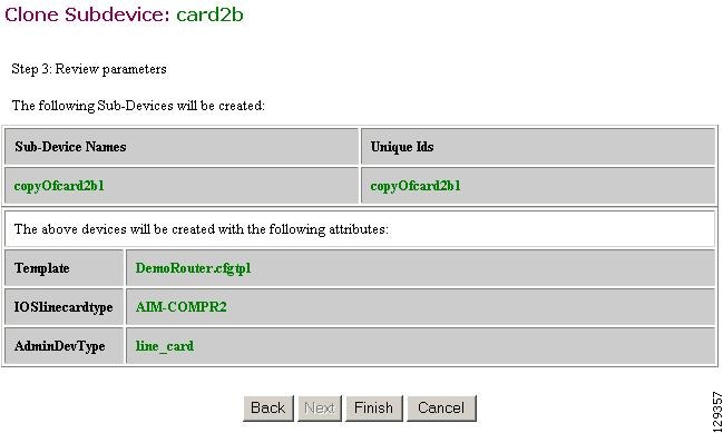
Step 4![]() Review the parameters you set for this clone.
Review the parameters you set for this clone.
Step 5![]() If you want to make changes, click
Back
.
If you want to make changes, click
Back
.
Step 6![]() To finish this task, click
Finish
.
To finish this task, click
Finish
.
Deleting Subdevices
Step 1![]() From the Subdevices Functional Overview page, click
Delete Device
.
From the Subdevices Functional Overview page, click
Delete Device
.
The Delete Subdevice page appears (see Figure 3-55).
Figure 3-55 Select Subdevices to Delete
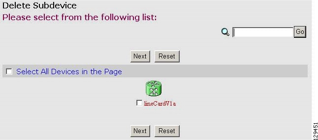
Step 2![]() Check to select the subdevice(s) you want to delete.
Check to select the subdevice(s) you want to delete.
Step 3![]() To proceed, click
Next
.
To proceed, click
Next
.
A status page appears indicating that the subdevice has been selected for deletion (see Figure 3-56).
Figure 3-56 Delete Subdevices Confirmation
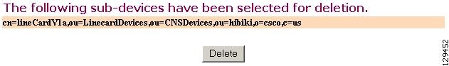
Step 4![]() To delete this subdevice, click
Delete
.
To delete this subdevice, click
Delete
.
Querying Device Inventory
You can use the Query Device Inventory feature to get a reports from devices about:
Step 1![]() From the Devices Functional Overview page, click
Query Device Inventory
.
From the Devices Functional Overview page, click
Query Device Inventory
.
The Query Device Inventory screen appears.
Figure 3-57 Query Device Inventory Page
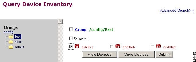
Step 2![]() Check the device(s) for which you want to get an inventory report(s), then click Submit.
Check the device(s) for which you want to get an inventory report(s), then click Submit.
The Query Notification Information page appears (see Figure 3-58).
Figure 3-58 Query Notification Information Page
Step 3![]() If you want an email notification sent when the query completes, fill in the information on this page, then click
Next
.
If you want an email notification sent when the query completes, fill in the information on this page, then click
Next
.
Note This page is optional. You can continue by clicking Next.
The Query Attributes Page appears (see Figure 3-59).
Figure 3-59 Query Attributes Page.
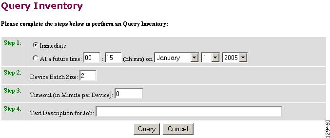
Step 4![]() Set all applicable attributes, then click
Query
.
Set all applicable attributes, then click
Query
.
The query is submitted as a Job . A page appears indicating the job number for this query.
Step 5![]() To check the status of this job, go to
Jobs > Query Job
.
To check the status of this job, go to
Jobs > Query Job
.
Step 6![]() Use the drop-down arrow to select Completed Jobs.
Use the drop-down arrow to select Completed Jobs.
Step 7![]() For the Inventory Job you want, click either the job number or the entry in the Status column.
For the Inventory Job you want, click either the job number or the entry in the Status column.
The Job Status page appears (see Figure 3-60).
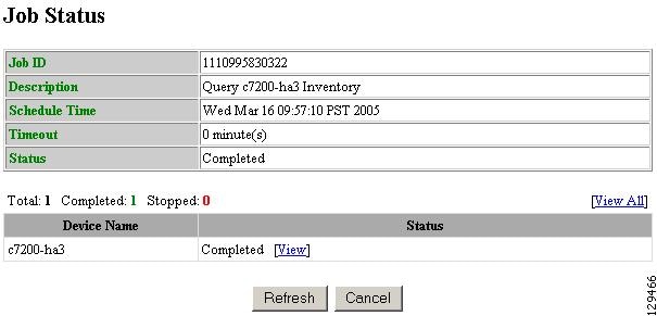
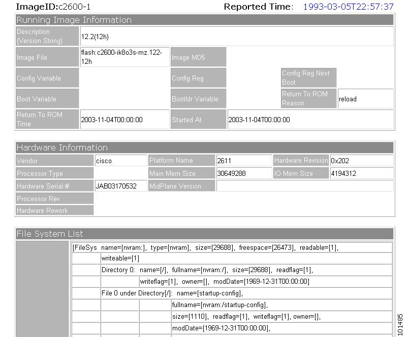
Step 8![]() To view the inventory report, click
View
.
To view the inventory report, click
View
.
Device inventory report appears (see Figure 3-61).
Figure 3-61 Sample Device Inventory Report
Delete Files on Device
Step 1![]() From the Devices Functional Overview page, click
Delete Files on Device
.
From the Devices Functional Overview page, click
Delete Files on Device
.
The Delete File on Device page appears (see Figure 3-62).
Figure 3-62 Delete Files on Device Page
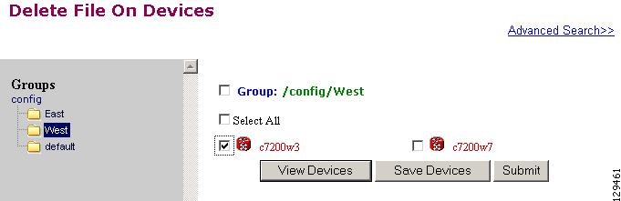
Step 2![]() Check the device(s) on which you want to delete files, then click Submit.
Check the device(s) on which you want to delete files, then click Submit.
The Delete Device Files Notification Information page appears (see Figure 3-63).
Figure 3-63 Delete Device Files Notification Information Page
Step 3![]() If you want an email notification sent when the query completes, fill in the information on this page, then click
Next
.
If you want an email notification sent when the query completes, fill in the information on this page, then click
Next
.
This page is optional. You can continue by clicking Next .
The Delete Files parameter page appears (see Figure 3-64).
Figure 3-64 Delete Files Parameter Page
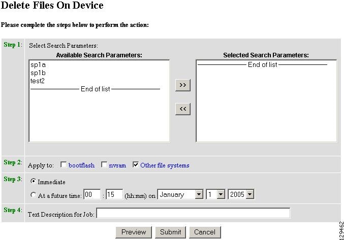
Step 4![]() Complete the steps on this page, then to preview, click
Preview
.
Complete the steps on this page, then to preview, click
Preview
.
Step 5![]() When you are satisfied with the task parameters, click
Submit
.
When you are satisfied with the task parameters, click
Submit
.
Dynamic Operations
Dynamic Operations allows you to perform operations on devices that all respond to having the same attributes based on the Query used to find them.
To use this feature you must have query objects available before starting Dynamic Operations. If no Queries have been created, you will see a message stating that there are no query objects available.
To create a Query, go to the “Creating Queries” section.
Step 1![]() From the Devices Functional Overview page, click
Dynamic Operations
.
From the Devices Functional Overview page, click
Dynamic Operations
.
The Dynamic Operations page appears (see Figure 3-65).
Figure 3-65 Dynamic Operations Page
Step 2![]() Use the down-arrow key to select the Query you want to use.
Use the down-arrow key to select the Query you want to use.
Step 3![]() Select the operation you want to perform on devices that respond to the Query, then click
List Devices
.
Select the operation you want to perform on devices that respond to the Query, then click
List Devices
.
The result of the Query appears (see Figure 3-66).
Figure 3-66 Devices Responding to Query
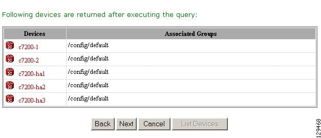
Step 4![]() To continue with the selected operation, click
Next
.
To continue with the selected operation, click
Next
.
 Feedback