IP Addresses and Services Configuration Guide for Cisco 8000 Series Routers, IOS XR Releases

PDF

IP Addresses and Services Configuration Guide for Cisco 8000 Series Routers, IOS XR Releases

IPv6 addresses

Want to summarize with AI?

Log in

Describes IPv6 interface addressing, including address-space scale, syntax, unicast types, packet headers, multicast groups, virtual management addresses, ICMP rate limiting, dual-stack configuration, and source-address selection.


An IPv6 address is an interface address that

  • enables forwarding of IPv6 traffic on a router interface

  • uses hexadecimal fields separated by colons, and

  • uses a prefix length to identify the network portion of the address.

By default, IPv6 addresses are not configured on interfaces.

The ipv6-prefix argument in the ipv6 address command must use hexadecimal values between colons. The prefix-length argument is a decimal value that identifies how many high-order contiguous bits compose the network portion of the address. A slash must precede the prefix length.

The maximum number of characters allowed for a prefix name is 128. Invalid prefix names are rejected.

The ipv6-address argument in the ipv6 address link-local command must use hexadecimal values between colons.


Larger IPv6 address space

Use this reference to compare the IPv6 address space with IPv4 and identify the operational effects of the larger IPv6 address space.

IPv6 address space characteristics include the following details:

  • IPv6 increases network address bits from 32 bits in IPv4 to 128 bits in IPv6.

  • IPv6 supports a much larger supply of globally unique IP addresses.

  • Globally unique IPv6 addresses support global reachability and end-to-end security for networked devices.

  • The flexibility of the IPv6 address space reduces the need for private addresses and Network Address Translation.

  • Mobile Internet-enabled devices, home-area networks, and wireless data services drive demand for globally unique IP addresses.

  • The IPv6 address space enables application protocols that do not require special processing by border routers at the edge of networks.


IPv6 address formats

An IPv6 address format is a text representation that

  • uses the format x:x:x:x:x:x:x:x

  • allows one double colon to compress the longest sequence of zero fields, and

  • uses a slash and prefix length to represent contiguous blocks of IPv6 address space.

The hexadecimal letters in IPv6 addresses are not case-sensitive. Two colons, ::, can be used only once in an IPv6 address.

Table 1. Compressed IPv6 address formats

IPv6 address type

Preferred format

Compressed format

Unicast

2001:0DB8:0:0:0:800:200C:417A

2001:DB8::800:200C:417A

Multicast

FF01:0:0:0:0:0:0:101

FF01::101

Loopback

0:0:0:0:0:0:0:1

::1

Unspecified

0:0:0:0:0:0:0:0

::

The IPv6 loopback address can be used by a node to send an IPv6 packet to itself. The loopback address cannot be assigned to a physical interface, and IPv6 routers do not forward packets that have the IPv6 loopback address as the source or destination address.

The unspecified IPv6 address indicates the absence of an IPv6 address. The unspecified address cannot be assigned to an interface and must not be used as a destination address in IPv6 packets or the IPv6 routing header.

An IPv6 address prefix uses the format ipv6-prefix/prefix-length. For example, 2001:0DB8:8086:6502::/32 is a valid IPv6 prefix.


IPv6 unicast addresses

An IPv6 unicast address is an address that

  • identifies one interface on one node

  • delivers a packet to the interface identified by that address, and

  • can be used for global, site-local, link-local, or IPv4-compatible IPv6 addressing.

Cisco IOS XR software supports these IPv6 unicast address types:

  • Aggregatable global addresses

  • Site-local addresses

  • Link-local addresses

  • IPv4-compatible IPv6 addresses


Aggregatable global IPv6 addresses

An aggregatable global IPv6 address is an IPv6 unicast address that

  • comes from the aggregatable global unicast prefix

  • supports strict aggregation of routing prefixes to limit global routing table entries, and

  • is used on links that are aggregated upward through organizations and Internet service providers.

Routing aggregation

The structure of aggregatable global IPv6 addresses enables strict aggregation of routing prefixes. This aggregation limits the number of routing table entries in the global routing table.

Aggregatable global addresses are used on links that are aggregated upward through organizations and eventually to Internet service providers.

Address structure

Aggregatable global IPv6 addresses are defined by these parts:

  • Global routing prefix

  • Subnet ID

  • Interface ID

Except for addresses that start with binary 000, all global unicast addresses have a 64-bit interface ID. The current global unicast address allocation uses the address range that starts with binary value 001, represented as 2000::/3.

Addresses with a prefix from 2000::/3 through E000::/3 are required to have 64-bit interface identifiers in the extended universal identifier 64-bit format.

The Internet Assigned Numbers Authority allocates IPv6 address space in the range 2000::/16 to regional registries.

Global routing prefix and subnet ID

The aggregatable global address typically consists of a 48-bit global routing prefix and a 16-bit subnet ID or Site-Level Aggregator.

In the IPv6 aggregatable global unicast address format document, RFC 2374, the global routing prefix included two additional hierarchically structured fields: Top-Level Aggregator and Next-Level Aggregator. The IETF removed the Top-Level Aggregator and Next-Level Aggregator fields from the RFCs because these fields are policy-based.

Some IPv6 networks that were deployed before the change might still use networks based on the older RFC 2374 architecture.

The 16-bit subnet ID can be used by individual organizations to create a local addressing hierarchy and identify subnets. A subnet ID is similar to a subnet in IPv4, except that an organization with an IPv6 subnet ID can support up to 65,535 individual subnets.

Interface ID requirements

An interface ID identifies interfaces on a link. The interface ID must be unique to the link and might also be unique over a broader scope.

In many cases, an interface ID is the same as, or based on, the link-layer address of an interface.

Interface IDs used in aggregatable global unicast and other IPv6 address types must be 64 bits long and constructed in the modified EUI-64 format.

Modified EUI-64 interface ID construction

For IEEE 802 interface types, such as Ethernet and FDDI interfaces, the modified EUI-64 interface ID is constructed from the 48-bit MAC address:

  • The first three octets, or 24 bits, are taken from the Organizationally Unique Identifier of the MAC address.

  • The fourth and fifth octets, or 16 bits, use the fixed hexadecimal value FFFE.

  • The last three octets, or 24 bits, are taken from the last three octets of the MAC address.

  • The Universal/Local bit, which is the seventh bit of the first octet, is set to indicate whether the IPv6 interface identifier is locally administered or globally unique.

A Universal/Local bit value of 0 indicates a locally administered identifier. A value of 1 indicates a globally unique IPv6 interface identifier.

For tunnel interface types that are used with IPv6 overlay tunnels, the interface ID is the IPv4 address assigned to the tunnel interface with all zeros in the high-order 32 bits of the identifier.

PPP and fallback interface ID behavior

For interfaces that use Point-to-Point Protocol, the interfaces at both ends of the connection might have the same MAC address. In this case, the interface identifiers used at both ends of the connection are negotiated, and reconstructed if necessary, until both identifiers are unique.

The first MAC address in the router is used to construct the identifier for interfaces that use Point-to-Point Protocol.

If no IEEE 802 interface types exist in the router, link-local IPv6 addresses are generated on the interfaces in this sequence:

  1. The router is queried for MAC addresses from the pool of MAC addresses in the router.

  2. If no MAC address is available, the serial number of the route processor or line card is used to form the link-local address.


Enable IPv6

Enable IPv6 processing to activate IPv6 on an interface and automatically configure a link-local address.

Procedure

  1. Enter interface configuration mode.

    Example:

    Router# configure
    Router(config)# interface HundredGigE 0/0/0/33
  2. Enable IPv6 processing on the interface.

    Example:

    Router(config-if)# ipv6 enable
  3. Enable the interface and commit the configuration.

    Example:

    Router(config-if)# no shutdown
    Router(config-if)# commit
  4. Verify the running configuration.

    Example:

    Router# show running-config interface HundredGigE 0/0/0/33
    interface HundredGigE0/0/0/33
     ipv6 enable
    !
  5. Verify that IPv6 is enabled.

    Example:

    Router# show ipv6 interface HundredGigE 0/0/0/33
    HundredGigE0/0/0/33 is Up, ipv6 protocol is Up, Vrfid is default (0x60000000)
    IPv6 is enabled, link-local address is fe80::7ae7:abff:febd:d4e4
    No global unicast address is configured
    Joined group address(es): ff02::1:ffbd:d4e4 ff02::2 ff02::1
    MTU is 1514 (1500 is available to IPv6)
    ICMP redirects are disabled
    ICMP unreachables are enabled
    ND DAD is enabled, number of DAD attempts 1

IPv6 is enabled on the interface with an automatically generated link-local address.


Configure IPv6 addresses

Configure an IPv6 address on an interface to enable IPv6 forwarding and create the associated link-local address.

Procedure

  1. Enter interface configuration mode.

    Example:

    Router# configure
    Router(config)# interface HundredGigE 0/0/0/25
  2. Assign the IPv6 address to the interface.

    Example:

    Router(config-if)# ipv6 address 2001:0DB8:0:1::1/64
  3. Enable the interface and commit the configuration.

    Example:

    Router(config-if)# no shutdown
    Router(config-if)# commit
  4. Verify the running configuration.

    Example:

    Router# show running-config interface HundredGigE 0/0/0/25
    interface HundredGigE0/0/0/25
     ipv6 address 2001:db8:0:1::1/64
    !
  5. Verify that the interface is active and IPv6 is enabled.

    Example:

    Router# show ipv6 interface HundredGigE 0/0/0/25
    HundredGigE0/0/0/25 is Up, ipv6 protocol is Up, Vrfid is default (0x60000000)
    IPv6 is enabled, link-local address is fe80::7ae7:abff:febd:d4c4
    Global unicast address(es):
      2001:db8:0:1::1, subnet is 2001:db8:0:1::/64
      2001:db8:0:1:7ae7:abff:febd:d4c4, subnet is 2001:db8:0:1::/64
    Joined group address(es): ff02::1:ff00:1 ff02::1:ffbd:d4c4 ff02::2
    ff02::1
    MTU is 1514 (1500 is available to IPv6)
    ICMP redirects are disabled
    ICMP unreachables are enabled
    ND DAD is enabled, number of DAD attempts 1
    Table Id is 0xe0800000

The interface has an IPv6 address, IPv6 is enabled, and the interface has joined the required IPv6 multicast groups.


Configure IPv6 addresses with EUI-64 interface identifiers

Configure the eui-64 keyword when only the 64-bit network prefix is specified and the interface identifier must be computed automatically.

Procedure

  1. Enter interface configuration mode.

    Example:

    Router# configure
    Router(config)# interface HundredGigE 0/0/0/35
  2. Assign the IPv6 prefix with the eui-64 keyword.

    Example:

    Router(config-if)# ipv6 address 2001:0DB8:0:1::/64 eui-64
  3. Enable the interface and commit the configuration.

    Example:

    Router(config-if)# no shutdown
    Router(config-if)# commit
  4. Verify the running configuration.

    Example:

    Router# show running-config interface HundredGigE 0/0/0/35
    interface HundredGigE0/0/0/35
     ipv6 address 2001:db8:0:1::/64 eui-64
    !
  5. Verify that the interface is active and IPv6 is enabled.

    Example:

    Router# show ipv6 interface HundredGigE 0/0/0/35
    HundredGigE0/0/0/35 is Up, ipv6 protocol is Up, Vrfid is default (0x60000000)
    IPv6 is enabled, link-local address is fe80::7ae7:abff:febd:d4ec
    Global unicast address(es):
      2001:db8:0:1:7ae7:abff:febd:d4ec, subnet is 2001:db8:0:1::/64
    Joined group address(es): ff02::1:ffbd:d4ec ff02::2 ff02::1
    MTU is 1514 (1500 is available to IPv6)
    ICMP redirects are disabled
    ICMP unreachables are enabled
    ND DAD is enabled, number of DAD attempts 1

The interface has an IPv6 address whose interface identifier is generated automatically from EUI-64 information.


IPv4-compatible IPv6 addresses

An IPv4-compatible IPv6 address is an IPv6 unicast address that

  • has zeros in the high-order 96 bits

  • contains an IPv4 address in the low-order 32 bits, and

  • is assigned to nodes that support both IPv4 and IPv6 protocol stacks.

The format of an IPv4-compatible IPv6 address is 0:0:0:0:0:0:A.B.C.D or ::A.B.C.D.

The entire 128-bit IPv4-compatible IPv6 address is used as the IPv6 address of a node. The embedded IPv4 address is used as the IPv4 address of the node.

IPv4-compatible IPv6 addresses are used in automatic tunnels.

This figure displays the format of an IPv4-compatible IPv6 address.

Figure 2. IPv4-compatible IPv6 address format
ipv4-compatible ipv6 address format

IPv6 packet headers

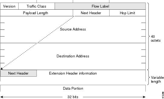
An IPv6 packet header is a network-layer header that

  • uses eight fields in the basic IPv6 packet header

  • has a total basic header size of 40 octets, and

  • can be followed by optional extension headers and the packet data.

IPv6 removes fields from the IPv4 packet header because IPv6 fragmentation is handled by the packet source and network-layer checksums are not used. Checksums are used at the data-link and transport layers. The basic IPv6 packet header and options fields are aligned to 64 bits.

Table 2. Basic IPv6 packet header fields

Field

Description

Version

Identifies the packet as IPv6 by using the value 6.

Traffic Class

Tags packets with a traffic class used in differentiated services.

Flow Label

Tags packets with a specific flow that differentiates packets at the network layer.

Payload Length

Identifies the total length of the data portion of the packet.

Next Header

Identifies the type of information that follows the basic IPv6 header, such as a transport-layer packet or extension header.

Hop Limit

Specifies the maximum number of routers an IPv6 packet can pass through before the packet is considered invalid.

Source Address

Contains a 128-bit IPv6 source address.

Destination Address

Contains a 128-bit IPv6 destination address.

There is no fixed number of extension headers in an IPv6 packet. Extension headers form a chain, and each extension header is identified by the Next Header field of the previous header.

Figure 3. IPv6 packet header format
ipv6 packet header format

IPv6 extension header chain

The optional extension headers and the packet data follow the eight fields of the basic IPv6 packet header.

If extension headers are present, each extension header is aligned to 64 bits. An IPv6 packet does not have a fixed number of extension headers. The extension headers form a chain, and each extension header is identified by the Next Header field of the previous header.

Typically, the final extension header has a Next Header field value for a transport-layer protocol, such as TCP or UDP.

Figure 4. IPv6 extension header format
ipv6 extension header format
Table 3. IPv6 extension header types

Header type

Next Header value

Description

Hop-by-hop options header

0

Processed by all hops in the packet path.

Destination options header

60

The destination options header can appear in either of these positions:

  • After a hop-by-hop options header: The destination options header is processed at the final destination and at each visited address specified by a routing header.

  • After an Encapsulating Security Payload (ESP) header: The destination options header is processed only at the final destination.

Routing header

43

Used for source routing.

Fragment header

44

Used when a source must fragment a packet that is larger than the path MTU. The Fragment header is used in each fragmented packet.

Authentication header and ESP header

51 and 50

Used by IPSec to provide authentication, integrity, and confidentiality. These headers are identical for both IPv4 and IPv6.

Upper-layer header

6 (TCP) and 17 (UDP)

Identifies TCP or UDP transport headers.

Mobility header

Assigned by IANA

Used by mobile nodes, correspondent nodes, and home agents for mobility binding messages.


IPv6 multicast groups

IPv6 multicast groups are link-scoped group addresses that

  • are joined automatically when IPv6 is configured on an interface

  • support neighbor discovery and router discovery, and

  • include solicited-node, all-nodes, and all-routers groups.

An IPv6 address must be configured on an interface for the interface to forward IPv6 traffic. Configuring a global IPv6 address automatically configures a link-local address and activates IPv6 on the interface.

The configured interface automatically joins these required multicast groups for the link:

  • Solicited-node multicast group FF02:0:0:0:0:1:FF00::/104 for each unicast address assigned to the interface

  • All-nodes link-local multicast group FF02::1

  • All-routers link-local multicast group FF02::2

The solicited-node multicast address is used in the neighbor discovery process.


Configure IPv4 and IPv6 protocol stacks

Configure both IPv4 and IPv6 on an interface when the interface must send and receive data on IPv4 and IPv6 networks.

Procedure

  1. Enter interface configuration mode.

    Example:

    Router# configure
    Router(config)# interface HundredGigE 0/0/0/31
  2. Assign the IPv4 address.

    Example:

    Router(config-if)# ipv4 address 192.0.2.1 255.255.255.0
  3. Assign the IPv6 address.

    Example:

    Router(config-if)# ipv6 address 2001:0DB8:c18:1::3/64
  4. Enable the interface and commit the configuration.

    Example:

    Router(config-if)# no shutdown
    Router(config-if)# commit
  5. Verify the running configuration.

    Example:

    Router# show running-config interface HundredGigE 0/0/0/31
    interface HundredGigE0/0/0/31
     ipv4 address 192.0.2.1 255.255.255.0
     ipv6 address 2001:db8:c18:1::3/64
    !
  6. Verify that IPv4 is enabled.

    Example:

    Router# show ipv4 interface HundredGigE 0/0/0/31
    HundredGigE0/0/0/31 is Up, ipv4 protocol is Up
    Vrf is default (vrfid 0x60000000)
    Internet address is 192.0.2.1/24
    MTU is 1514 (1500 is available to IP)
    Helper address is not set
    Directed broadcast forwarding is disabled
    ICMP redirects are never sent
    ICMP unreachables are always sent
    Table Id is 0xe0000000
  7. Verify that IPv6 is enabled.

    Example:

    Router# show ipv6 interface HundredGigE 0/0/0/31
    HundredGigE0/0/0/31 is Up, ipv6 protocol is Up, Vrfid is default (0x60000000)
    IPv6 is enabled, link-local address is fe80::7ae7:abff:febd:d4dc
    Global unicast address(es):
      2001:db8:c18:1::3, subnet is 2001:db8:c18:1::/64
    Joined group address(es): ff02::1:ff00:3 ff02::1:ffbd:d4dc ff02::2
    ff02::1
    MTU is 1514 (1500 is available to IPv6)
    ICMP redirects are disabled
    ICMP unreachables are enabled
    ND DAD is enabled, number of DAD attempts 1

The interface forwards both IPv4 and IPv6 traffic.


IPv6 virtual addresses

An IPv6 virtual address is a management address that

  • lets you access the router from a single IPv6 address on a management network without knowing which route processor is active

  • persists across route processor failover, and

  • must share a common IPv6 subnet with a Management Ethernet interface on both route processors.

VRF support

The vrf keyword supports virtual addresses on a per-VRF basis.

Source address selection

The use-as-src-addr keyword eliminates the need to configure a loopback interface as the update source for management applications.

When an update source is not configured, management applications allow transport processes such as TCP, UDP, and raw_ip to select a suitable source address. The transport processes consult the FIB to select the source address.

If a Management Ethernet IPv6 address is selected and use-as-src-addr is configured, the transport process substitutes the Management Ethernet IPv6 address with the relevant virtual IPv6 address. This behavior works across route processor switchovers.

If use-as-src-addr is not configured, the source address selected by the transport process can change after failover, and the network management system might not be able to handle the change.

Protocol source address behavior

Protocol configuration, such as tacacs source-interface , snmp-server trap-source , ntp source , and logging source-interface , does not use the virtual management IPv6 address as its source by default.

Use the ipv6 virtual address use-as-src-addr command to ensure that the protocol uses the virtual IPv6 address as its source address.

Alternatively, configure a loopback address with the required IPv6 address and set it as the source interface for the protocol, such as TACACS+, by using tacacs source-interface .


Configure IPv6 virtual addresses

Configure IPv6 virtual addresses to provide stable management access across route processor failover.

The virtual IPv6 address must share a common IPv6 subnet with a Management Ethernet interface on both route processors.

Procedure

  1. Configure the IPv6 virtual address.

    Example:

    Router# configure terminal
    Router(config)# ipv6 virtual address 2001:0DB8:0:1::1/64
    Router(config)# commit
  2. Configure the Management Ethernet interface in the same subnet.

    Example:

    Router# configure terminal
    Router(config)# ipv6 virtual address 2001:DB8:0:1::1/64
    Router(config)# interface MgmtEth 0/RP0/CPU0/0
    Router(config-if)# ipv6 address 2001:0DB8:0:1::1/64
    Router(config-if)# no shutdown
    Router(config-if)# commit
    Router(config-if)# exit
  3. Verify the Management Ethernet interface configuration.

    Example:

    Router# show running-config interface MgmtEth 0/RP0/CPU0/0
    interface MgmtEth0/RP0/CPU0/0
     ipv6 address 2001:db8:0:1::1/64
    !
  4. Configure the IPv6 virtual address for a VRF.

    Example:

    Router# configure terminal
    Router(config)# ipv6 virtual address vrf Test 2001:0DB8:0:1::1/64
    Router(config)# interface MgmtEth 0/RP0/CPU0/0
    Router(config-if)# ipv6 address 2001:0DB8:0:1::1/64
    Router(config-if)# no shutdown
    Router(config-if)# commit
  5. Verify the VRF interface configuration.

    Example:

    Router# show running-config interface MgmtEth 0/RP0/CPU0/0
    interface MgmtEth0/RP0/CPU0/0
     ipv6 address 2001:db8:0:1::1/64
    !

IPv6 ICMP rate limiting

IPv6 ICMP rate limiting is an error-message control feature that

  • limits the rate at which IPv6 ICMP error messages are sent on the network

  • uses tokens to represent permission to send error messages, and

  • allows a burst of error messages until the token bucket is empty.

A token bucket scheme lets applications such as traceroute receive replies to a group of requests sent in rapid succession. Each error message removes one token from the bucket. When the bucket is empty, IPv6 ICMP error messages are not sent until a new token is added.

The token bucket algorithm is more flexible than a fixed time interval scheme and does not increase the average rate-limiting time interval.


Configure IPv6 ICMP rate limiting

Configure IPv6 ICMP rate limiting to control how often IPv6 ICMP error messages are sent.

The milliseconds argument specifies the interval between tokens being added to the bucket. The optional bucketsize argument defines the maximum number of tokens stored in the bucket.

Procedure

  1. Configure the interval and bucket size for IPv6 ICMP error messages.

    Example:

    Router# configure
    Router(config)# ipv6 icmp error-interval 50 20
    Router(config)# commit
  2. Verify the IPv6 ICMP error interval configuration.

    Example:

    Router# show running-config | include ipv6 icmp
    ipv6 icmp error-interval 50 20

The IPv6 ICMP error interval is configured with a 50 millisecond token interval and a bucket size of 20 tokens.


Flexible source IP

Flexible source IP is an ICMP source-address selection behavior that

  • selects the source IP address in ICMP response packets

  • helps respond to packet-forwarding failures, and

  • can be configured for RFC-compliant IPv4 ICMP source address selection.

The related command family includes icmp ipv4 source vrf .


Configure flexible source IP for ICMP

Configure flexible source IP for ICMP when ICMP response packets must use RFC-compliant source address selection.

Procedure

  1. Enable RFC-compliant source address selection for IPv4 ICMP.

    Example:

    Router# configure
    Router(config)# icmp ipv4 source rfc
    Router(config)# commit
  2. Verify the source address selection configuration.

    Example:

    Router# show running-config | include source rfc
    icmp ipv4 source rfc

RFC-compliant source address selection is enabled for IPv4 ICMP response packets.