IP Addresses and Services Configuration Guide for Cisco 8000 Series Routers, IOS XR Releases

PDF

IP Addresses and Services Configuration Guide for Cisco 8000 Series Routers, IOS XR Releases

How to implement network stack IPv4 and IPv6

Want to summarize with AI?

Log in

Describes IPv4 implementation workflows, including access prerequisites, primary and secondary interface addressing, virtual management addresses, ICMP rate limiting, and unnumbered point-to-point interfaces.


Prerequisites for implementing network stack IPv4 and IPv6

Use this reference to confirm the required authorization before you configure network stack IPv4 and IPv6 features.

Network Stack IPv4 and IPv6 tasks require the correct user group assignment:

  • You must be in a user group that is associated with a task group that includes the required task IDs.

  • The command reference guides list the task IDs required for each command.

  • If user group assignment prevents command use, contact your AAA administrator for assistance.
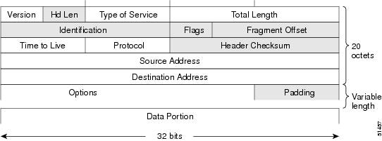

IPv4 packet headers

An IPv4 packet header is a network-layer packet header that

  • contains 12 basic fields

  • has a basic header size of 20 octets, or 160 bits, and

  • can include an Options field before the packet data portion.

Basic header size

The basic IPv4 packet header has 12 fields with a total size of 20 octets, or 160 bits.

Options and data portion

The 12 basic header fields can be followed by an Options field. The Options field is followed by the data portion, which is usually the transport-layer packet.

The variable length of the Options field adds to the total size of the IPv4 packet header.

Header fields

This figure displays IPv4 packet header format.

Figure 1. IPv4 packet header format
IPv4 packet header

The IPv4 packet header format includes these fields and areas:

  • Version

  • Header Length

  • Type of Service

  • Total Length

  • Identification

  • Flags

  • Fragment Offset

  • Time to Live

  • Protocol

  • Header Checksum

  • Source Address

  • Destination Address

  • Options

  • Padding

  • Data Portion


IPv4 addresses

An IPv4 address is an interface identifier that

  • identifies a location where IPv4 datagrams can be sent

  • enables communication with hosts on the configured interface, and

  • uses a network mask or prefix length to identify the network portion of the address.

An interface can have one primary IPv4 address and multiple secondary IPv4 addresses. Packets generated by the software use the primary IPv4 address. Therefore, all networking devices on a segment should share the same primary network number.

Starting with Cisco IOS XR Release 7.10.2, the CLI does not accept IPv4 addresses with leading zeros. Use canonical dotted-decimal IPv4 addresses, such as 198.51.100.1. NETCONF and YANG reject IPv4 addresses that contain leading zeros.

Cisco supports only network masks that use contiguous bits that are flush left against the network field.

A network mask can be a four-part dotted decimal address, such as 255.255.255.0, or a slash and prefix length, such as /24. In prefix-length notation, the slash must immediately follow the IPv4 address.


Configure IPv4 addresses

Configure IPv4 addresses on interfaces to enable IPv4 communication with hosts on those interfaces.

Before you configure IPv4 on an interface, confirm the primary address, prefix length, and network mask requirements.

Procedure

  1. Enter interface configuration mode.

    Example:

    Router# configure
    Router(config)# interface HundredGigE 0/0/0/24
  2. Assign the IPv4 address and prefix length to the interface.

    Example:

    Router(config-if)# ipv4 address 198.51.100.1/24
  3. Enable the interface and commit the configuration.

    Example:

    Router(config-if)# no shutdown
    Router(config-if)# commit
  4. Verify the running configuration.

    Example:

    Router# show running-config interface HundredGigE 0/0/0/24
    interface HundredGigE0/0/0/24
     ipv4 address 198.51.100.1 255.255.255.0
    !
  5. Verify that the interface is active and IPv4 is enabled.

    Example:

    Router# show ipv4 interface HundredGigE 0/0/0/24
    HundredGigE0/0/0/24 is Up, ipv4 protocol is Up
    Vrf is default (vrfid 0x60000000)
    Internet address is 198.51.100.1/24
    MTU is 1514 (1500 is available to IP)
    Helper address is not set
    Directed broadcast forwarding is disabled
    Outgoing access list is not set
    Inbound common access list is not set, access list is not set
    Proxy ARP is disabled
    ICMP redirects are never sent
    ICMP unreachables are always sent
    ICMP mask replies are never sent
    Table Id is 0xe0000000

The interface has a primary IPv4 address and IPv4 is operational on the interface.


IPv4 virtual addresses

An IPv4 virtual address is a management address that

  • lets you access the router from a single IPv4 address without knowing which route processor is active

  • persists across route processor failover, and

  • must share a common IPv4 subnet with a Management Ethernet interface on both route processors.

The vrf keyword supports virtual addresses on a per-VRF basis.

The use-as-src-addr keyword lets management applications use a relevant virtual IPv4 address as the source address when the transport process selects a Management Ethernet address. This behavior works across route processor switchovers. Without the keyword, the selected source address can change after failover and network management software might not handle the change.

Protocol configurations such as tacacs source-interface , snmp-server trap-source , ntp source , and logging source-interface do not use the virtual management IPv4 address as the source by default. Use the ipv4 virtual address use-as-src-addr command, or configure a loopback address and set it as the source interface for the protocol.


Configure IPv4 virtual addresses

Configure IPv4 virtual addresses to provide stable management access across route processor failover.

The virtual IPv4 address must share a common IPv4 subnet with a Management Ethernet interface on both route processors.

Procedure

  1. Configure the IPv4 virtual address.

    Example:

    Router# configure terminal
    Router(config)# ipv4 virtual address 192.0.2.28/24
    Router(config)# commit
  2. Configure the Management Ethernet interface in the same subnet.

    Example:

    Router# configure terminal
    Router(config)# ipv4 virtual address 192.0.2.28/24
    Router(config)# interface MgmtEth 0/RP0/CPU0/0
    Router(config-if)# ipv4 address 192.0.2.28/24
    Router(config-if)# no shutdown
    Router(config-if)# commit
    Router(config-if)# exit
  3. Verify the Management Ethernet interface configuration.

    Example:

    Router# show running-config interface MgmtEth 0/RP0/CPU0/0
    interface MgmtEth0/RP0/CPU0/0
     ipv4 address 192.0.2.28 255.255.255.0
    !
  4. Configure the Management Ethernet interface in a VRF when virtual management access is required for that VRF.

    Example:

    Router# configure terminal
    Router(config)# interface MgmtEth 0/RP0/CPU0/0
    Router(config-if)# vrf test
    Router(config-if)# ipv4 address 192.0.2.29 255.255.255.0
    Router(config-if)# no shutdown
    Router(config-if)# commit
  5. Verify the VRF interface configuration.

    Example:

    Router# show running-config interface MgmtEth 0/RP0/CPU0/0
    interface MgmtEth0/RP0/CPU0/0
     vrf test
     ipv4 address 192.0.2.29 255.255.255.0
    !

The IPv4 virtual address and Management Ethernet interface configuration are available for management access.


IPv4 ICMP rate limiting

IPv4 ICMP rate limiting is a control-plane protection feature that

  • limits the rate at which IPv4 ICMP destination unreachable messages are generated

  • uses one timer for general destination unreachable messages, and

  • uses a separate timer for Don't Fragment (DF) destination unreachable messages when the DF keyword is configured.

The general destination unreachable timer and DF destination unreachable timer share the same limits and defaults. When the DF keyword is configured, the DF timer remains independent from the general destination unreachable timer.

The optional DF keyword limits ICMP destination unreachable messages sent when code 4 fragmentation is needed and Don't Fragment is set in the IP header.

Use the show ipv4 traffic command to identify how many ICMP unreachable messages were sent or received.


Configure IPv4 ICMP rate limiting

Configure IPv4 ICMP rate limiting to control the rate at which IPv4 ICMP destination unreachable messages are generated.

Configure the general destination unreachable rate limit and, when required, configure an independent DF destination unreachable rate limit.

Procedure

  1. Configure the general IPv4 ICMP destination unreachable rate limit.

    Example:

    Router# configure
    Router(config)# icmp ipv4 rate-limit unreachable 1000
  2. Configure the DF destination unreachable rate limit.

    Example:

    Router(config)# icmp ipv4 rate-limit unreachable DF 1000
    Router(config)# commit
  3. Verify the ICMP rate-limit configuration.

    Example:

    Router# show running-config | in icmp
    Building configuration...
    icmp ipv4 rate-limit unreachable DF 1000
    icmp ipv4 rate-limit unreachable 1000
  4. Verify that IPv4 is operational on the interface.

    Example:

    Router# show ipv4 interface HundredGigE0/0/0/2
    HundredGigE0/0/0/2 is Up, ipv4 protocol is Up
    Vrf is default (vrfid 0x60000000)
    Internet address is 192.0.2.2/24
    MTU is 1514 (1500 is available to IP)
    Helper address is not set
    Multicast reserved groups joined: 224.0.0.2 224.0.0.1 224.0.0.2
    224.0.0.5 224.0.0.6
    Directed broadcast forwarding is disabled
    Outgoing access list is not set
    Inbound common access list is not set, access list is not set
    Proxy ARP is disabled
    ICMP redirects are never sent
    ICMP unreachables are always sent
    ICMP mask replies are never sent
    Table Id is 0xe0000000
  5. Verify the ICMP unreachable counters.

    Example:

    Router# show ipv4 traffic
    ICMP statistics:
    Sent: 0 admin unreachable, 5 network unreachable
    0 host unreachable, 0 protocol unreachable
    0 port unreachable, 0 fragment unreachable
    0 time to live exceeded, 0 reassembly ttl exceeded
    0 echo request, 0 echo reply
    0 mask request, 0 mask reply
    0 parameter error, 0 redirects
    5 total
    Rcvd: 0 admin unreachable, 0 network unreachable
    0 host unreachable, 0 protocol unreachable
    0 port unreachable, 0 fragment unreachable
    0 time to live exceeded, 0 reassembly ttl exceeded
    0 echo request, 0 echo reply
    0 mask request, 0 mask reply
    0 redirect, 0 parameter error
    0 source quench, 0 timestamp, 0 timestamp reply
    0 router advertisement, 0 router solicitation
    0 total, 0 checksum errors, 0 unknown

IPv4 processing on an unnumbered interface

IPv4 processing on an unnumbered interface is an interface addressing method that

  • enables IPv4 on a point-to-point interface without assigning an explicit IPv4 address to that interface

  • uses the address of a specified interface as the source address for generated packets, and

  • uses the specified interface address to determine which routing processes send updates over the unnumbered interface.

An unnumbered interface has no IPv4 address of its own. You cannot use the ping EXEC command to determine whether the unnumbered interface is up. Use SNMP to remotely monitor interface status.

IP security options are not supported on an unnumbered interface.


Enable IPv4 processing on unnumbered interfaces

Enable IPv4 processing on an unnumbered interface when a point-to-point interface must use the IPv4 address of another interface as its source address.

Identify the point-to-point interface and the loopback interface whose IPv4 address the unnumbered interface must use.

Procedure

  1. Enter interface configuration mode for the point-to-point interface.

    Example:

    Router# configure
    Router(config)# interface HundredGigE 0/0/0/25
  2. Enable IPv4 point-to-point processing and commit the configuration.

    Example:

    Router(config-if)# ipv4 point-to-point
    Router(config-if)# commit
  3. Configure the interface to use the loopback interface IPv4 address and commit the configuration.

    Example:

    Router(config-if)# ipv4 unnumbered loopback 0
    Router(config-if)# commit
  4. Verify the unnumbered interface configuration.

    Example:

    Router# show running-config interface HundredGigE 0/0/0/25
    interface HundredGigE0/0/0/25
     ipv4 point-to-point
     ipv4 unnumbered Loopback0
    !
  5. Verify that the unnumbered interface is up.

    Example:

    Router# show interface HundredGigE 0/0/0/25
    HundredGigE0/0/0/25 is up, line protocol is up
    Interface state transitions: 5
    Hardware is HundredGigE, address is 00e2.2a33.445b (bia 00e2.2a33.445b)
    Layer 1 Transport Mode is LAN
    Internet address is 192.0.2.1/24
    MTU 1514 bytes, BW 10000000 Kbit (Max: 10000000 Kbit)
    reliability 255/255, txload 194/255, rxload 0/255
    Encapsulation ARPA,
    Full-duplex, 10000Mb/s, link type is force-up
  6. Verify the loopback interface configuration.

    Example:

    Router# show running-config interface Loopback 0
    interface Loopback0
     ipv4 address 192.0.2.1 255.255.255.255

Secondary IPv4 addresses on network interfaces

A secondary IPv4 address is an additional interface address that

  • supplements the primary IPv4 address on a network interface

  • lets one interface support more than one logical IPv4 subnet on the same physical segment, and

  • is configured with the secondary keyword.

Cisco IOS XR software supports multiple secondary IPv4 addresses per interface.

For IPv6, an interface can have multiple IPv6 addresses without the secondary keyword.


Guidelines for secondary IPv4 addresses on network interfaces

Use these guidelines before you configure secondary IPv4 addresses on a network segment.

Table 1. Secondary IPv4 address guidelines

Guideline

Details

Use secondary addresses when a segment needs more host addresses.

If subnetting allows up to 254 hosts per logical subnet but a physical subnet needs 300 host addresses, secondary IPv4 addresses let routers or access servers support two logical subnets on one physical subnet.

Use secondary addresses during migration from bridged networks.

Older Layer 2 bridged networks that were not subnetted can use secondary IPv4 addresses during migration to a subnetted, router-based network. Routers on the segment can become aware that many subnets are on that segment.

Use secondary addresses to join separated subnets of the same network.

You can create a single network from subnets that are physically separated by another network by using a secondary address. In this design, the first network is extended or layered on top of the second network.

Do not place the same subnet on more than one active interface.

A subnet cannot appear on more than one active interface of the router at a time.

Keep secondary-address use consistent across the segment.

If any router on a network segment uses a secondary IPv4 address, all other routers on that same segment must also use a secondary address from the same network or subnet.

Avoid inconsistent secondary-address use.

Inconsistent use of secondary addresses on a network segment can quickly cause routing loops.


Configure secondary IPv4 addresses on network interfaces

Configure secondary IPv4 addresses when an interface must support more than one IPv4 subnet on the same physical network segment.

Identify the interface, primary IPv4 address, and secondary IPv4 address before you configure the secondary address.

Procedure

  1. Enter interface configuration mode.

    Example:

    Router# configure
    Router(config)# interface HundredGigE 0/0/0/24
  2. Assign the secondary IPv4 address to the interface and commit the configuration.

    Example:

    Router(config-if)# ipv4 address 192.0.2.1 255.255.255.0 secondary
    Router(config-if)# commit
  3. Verify the running configuration.

    Example:

    Router# show running-config interface HundredGigE 0/0/0/24
    interface HundredGigE0/0/0/24
     ipv4 address 192.0.2.27 255.255.255.0
     ipv4 address 192.0.2.1 255.255.255.0 secondary
    !
  4. Verify that the interface lists the secondary IPv4 address.

    Example:

    Router# show ipv4 interface HundredGigE 0/0/0/24
    HundredGigE0/0/0/24 is Up, ipv4 protocol is Up
    Vrf is default (vrfid 0x60000000)
    Internet address is 192.0.2.27/24
    Secondary address 192.0.2.1/24
    MTU is 1514 (1500 is available to IP)
    Helper address is not set
    Directed broadcast forwarding is disabled
    Outgoing access list is not set
    Inbound common access list is not set, access list is not set
    Proxy ARP is disabled
    ICMP redirects are never sent
    ICMP unreachables are always sent
    ICMP mask replies are never sent
    Table Id is 0xe0000000