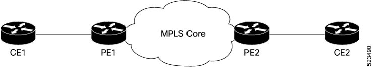
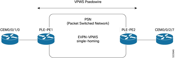
EVPN MPLS single-homing mode
EVPN MPLS single-homing is a network connectivity mode that
-
enables a single connection between a customer edge (CE) device and a provider edge (PE) device using MPLS as the transport protocol
-
simplifies network design by eliminating the need for redundant connections at the CE level, and
-
provides efficient Layer 2 and Layer 3 connectivity over an MPLS backbone.
EVPN MPLS single-homing is a cost-effective and simplified network solution designed for scenarios prioritizing cost efficiency and simplicity over redundancy. This mode is commonly used in environments where the customer edge (CE) device does not require a backup connection to the provider edge (PE) device, and is ideal for non-critical applications, such as small enterprises connecting branch offices to an MPLS network, as it reduces costs, simplifies deployment, and minimizes operational complexity.
EVPN control plane using BGP distributes MAC address information learned from the single-homed CE to other PEs, enabling Layer 2 bridging across the MPLS network.
EVPN MPLS single-homing mode services
The EVPN MPLS single-homing mode supports various service types to provide diverse network connectivity options. These services are designed to replace legacy technologies, offering enhanced flexibility, scalability, and fault tolerance. Both services utilize the EVPN control plane for scalability, redundancy, and efficient MAC address learning.
The EVPN MPLS single-homing mode supports these services:
-
EVPN E-LAN—EVPN E-LAN in EVPN MPLS single-homing offers multipoint-to-multipoint Layer 2 connectivity, enabling seamless communication among multiple sites as if they were on the same LAN. This solution is particularly suitable for scenarios requiring interconnectivity among more than two locations, such as data center interconnects or corporate WANs. For example, a company with offices in New York, London, and Tokyo can utilize EVPN E-LAN to interconnect these offices, allowing all sites to communicate as part of the same Ethernet network.
-
EVPN E-Line—EVPN E-Line in EVPN MPLS single-homing provides point-to-point Layer 2 connectivity between two endpoints, such as customer sites or data centers, making it an ideal solution for scenarios where direct communication is required over a service provider's MPLS or IP backbone. For instance, a business with offices in two cities can leverage EVPN E-Line to establish a direct, transparent Ethernet connection between the sites, ensuring seamless and efficient communication.
This table compares the key features and use cases of EVPN E-LAN and EVPN E-Line services.
|
Feature |
EVPN E-LAN |
EVPN E-Line |
|---|---|---|
|
Connectivity type |
Multipoint-to-Multipoint |
Point-to-Point |
|
Typical use cases |
Multi-site connectivity, interconnecting multiple locations |
Data center interconnects, connecting two sites |
|
MAC address learning |
Across all endpoints in the E-LAN |
Limited to two endpoints |
 Feedback