Advanced EVPN Configurations and Extensions

This chapter covers advanced EVPN E-LAN configurations, including VRF leaking for inter-VRF communication, MAC mobility with duplicate address detection for seamless device movement, and EVPN designated forwarder election. Users learn to enhance network resilience, optimize traffic distribution, and minimize disruptions during failover and recovery.

VRF leaking for EVPN E-LAN

A virtual routing and forwarding (VRF) instance is a network virtualization technology that

  • provides logical separation of network resources by creating multiple isolated virtual networks

  • operates independently with its own routing table, forwarding behavior, and network policies, and

  • enables communication among devices within the same VRF while isolating them from devices in other VRFs.

Table 1. Feature History Table

Feature Name

Release Information

Feature Description

VRF leaking for EVPN E-LAN

Release 25.3.1

Introduced in this release on: Centralized Systems (8400 [ASIC: K100]) (select variants only*)

*This feature is now supported on the Cisco 8404-SYS-D routers.

VRF leaking for EVPN E-LAN

Release 24.4.1

Introduced in this release on: Fixed Systems (8700) (select variants only*)

* The VRF leaking functionality is now extended to the Cisco 8712-MOD-M routers.

VRF leaking for EVPN E-LAN

Release 24.3.1

Introduced in this release on: Fixed Systems (8200, 8700); Modular Systems (8800 [LC ASIC: P100]) (select variants only*)

* The VRF leaking functionality is now extended to:

  • 8212-48FH-M

  • 8711-32FH-M

  • 88-LC1-52Y8H-EM

  • 88-LC1-12TH24FH-E

VRF leaking for EVPN E-LAN

Release 24.2.11

Introduced in this release on: Modular Systems (8800 [LC ASIC: P100]) (select variants only*)

* The VRF leaking functionality is now extended to routers with the 88-LC1-36EH line cards.

VRF leaking for EVPN E-LAN

Release 7.11.1

We now allow for seamless intercommunication between different VRF instances in an EVPN domain, thus enabling controlled inter-VRF communication and resource-sharing, which is helpful in multi-tenancy environments, data center deployments, and hybrid cloud scenarios.

This feature is supported only on Q200-based line cards.

Features of Layer 2 interconnection using VRF leaking

Layer 2 interconnection using VRF leaking in an EVPN network provides these features:

  • Enables controlled Layer 2 communication between different VRF instances by selectively sharing routes.

  • Maintains VRF isolation and segmentation while allowing traffic interconnection through EVPN Route type 2 (MAC+IP) import.

  • Permits interconnection of VRFs at Layer 2 using gateways or bridges that forward traffic between VRFs.

  • Allows definition of traffic policies to control flow, including filtering based on EVPN EVI and MAC addresses.

  • Forwards Layer 2 frames between VRFs while preserving Layer 3 isolation.

Configure VRF leaking for EVPN E-LAN

This procedure enables controlled route leaking between the global routing table and a VRF routing table within an EVPN E-LAN environment. VRF leaking allows selective sharing of routes between VRFs and the global routing table, facilitating communication across different routing domains while maintaining segmentation and policy control. This is essential in multi-tenant or segmented network architectures where certain routes need to be shared securely and efficiently.

Procedure


Step 1

Configure BGP where the router performs the route leak.

Example:

Router(config)# router bgp 100
Router(config-bgp)# bgp router-id 10.10.10.10
Router(config-bgp)# address-family ipv4 unicast
Router(config-bgp-af)# network 172.16.20.0/24
Router(config-bgp-af)# exit
Router(config-bgp)# address-family vpnv4 unicast
Router(config-bgp-af)# exit
Router(config-bgp)# vrf ORANGE
Router(config-bgp-vrf)# rd 100:100
Router(config-bgp-vrf)# address-family ipv4 unicast
Router(config-bgp-vrf-af)# network 192.168.10.0/24
Router(config-bgp-vrf-af)# commit

Step 2

Configure the route policies.

These policies help you filter which prefixes are permitted to be leaked. In this example, the route-policy GLOBAL-2-VRF and route-policy VRF-2-GLOBAL are used.

Example:

Router(config)# route-policy GLOBAL-2-VRF
Router(config-rpl)# if destination in (172.16.20.0/24) then
Router(config-rpl-if)# pass
Router(config-rpl-if)# endif
Router(config-rpl)# end-policy
Router(config)# route-policy VRF-2-GLOBAL
Router(config-rpl)# if destination in (192.168.10.0/24 le 32) then
Router(config-rpl-if)# pass
Router(config-rpl-if)# endif
Router(config-rpl)# end-policy

Step 3

Configure the VRF and apply the route-policy.

Example:


Router(config)# vrf ORANGE
Router(config-vrf)# address-family ipv4 unicast
Router(config-vrf-af)# import from default-vrf route-policy GLOBAL-2-VRF
Router(config-vrf-af)# import route-target
Router(config-vrf-import-rt)# 100:100
Router(config-vrf-import-rt)# exit
Router(config-vrf-af)# export to default-vrf route-policy VRF-2-GLOBAL
Router(config-vrf-af)# export route-target
Router(config-vrf-export-rt)# 100:100
Router(config-vrf-export-rt)# commit

Step 4

Running configuration of VRF leaking.

Example:


router bgp 100
 bgp router-id 10.10.10.10
 address-family ipv4 unicast
  network 172.16.20.0/24
 !
 address-family vpnv4 unicast
 !
 vrf ORANGE
  rd 100:100
  address-family ipv4 unicast
   network 192.168.10.0/24
  !
 !
!
route-policy GLOBAL-2-VRF
  if destination in (172.16.20.0/24) then
    pass
  endif
end-policy
!
route-policy VRF-2-GLOBAL
  if destination in (192.168.10.0/24 le 32) then
    pass
  endif
end-policy
!
vrf ORANGE
 address-family ipv4 unicast
  import from default-vrf route-policy GLOBAL-2-VRF
  import route-target
   100:100
  !
  export to default-vrf route-policy VRF-2-GLOBAL
  export route-target
   100:100
  !
 !
!

Step 5

Use the show route command to verify the prefixes appear in the RIB and BGP tables.

Example:

Router# show route
Codes: C - connected, S - static, R - RIP, B - BGP, (>) - Diversion path
       D - EIGRP, EX - EIGRP external, O - OSPF, IA - OSPF inter area
       N1 - OSPF NSSA external type 1, N2 - OSPF NSSA external type 2
       E1 - OSPF external type 1, E2 - OSPF external type 2, E - EGP
       i - ISIS, L1 - IS-IS level-1, L2 - IS-IS level-2
       ia - IS-IS inter area, su - IS-IS summary null, * - candidate default
       U - per-user static route, o - ODR, L - local, G  - DAGR, l - LISP
       A - access/subscriber, a - Application route
       M - mobile route, r - RPL, t - Traffic Engineering, (!) - FRR Backup path

Gateway of last resort is not set

C    10.88.174.0/24 is directly connected, 1d20h, MgmtEth0/RSP0/CPU0/0
L    10.88.174.223/32 is directly connected, 1d20h, MgmtEth0/RSP0/CPU0/0
L    10.10.10.10/32 is directly connected, 04:33:44, Loopback100
C    172.16.20.0/24 is directly connected, 07:03:18, HundredGigE0/0/0/24
L    172.16.20.1/32 is directly connected, 07:03:18, HundredGigE0/0/0/24
B    192.168.10.0/24 is directly connected, 03:02:21, HundredGigE0/0/0/0 (nexthop in vrf ORANGE)

Router# show ip bgp
BGP router identifier 10.10.10.10, local AS number 100
BGP generic scan interval 60 secs
Non-stop routing is enabled
BGP table state: Active
Table ID: 0xe0000000   RD version: 5
BGP main routing table version 5
BGP NSR Initial initsync version 3 (Reached)
BGP NSR/ISSU Sync-Group versions 0/0
BGP scan interval 60 secs

Status codes: s suppressed, d damped, h history, * valid, > best
              i - internal, r RIB-failure, S stale, N Nexthop-discard
Origin codes: i - IGP, e - EGP, ? - incomplete
   Network            Next Hop            Metric LocPrf Weight Path
*> 172.16.20.0/24     0.0.0.0                  0         32768 i
*> 192.168.10.0/24    0.0.0.0                  0         32768 i

Processed 2 prefixes, 2 paths

This show output displays the information for the VRF ORANGE:

Router# show route vrf ORANGE 
Codes: C - connected, S - static, R - RIP, B - BGP, (>) - Diversion path
       D - EIGRP, EX - EIGRP external, O - OSPF, IA - OSPF inter area
       N1 - OSPF NSSA external type 1, N2 - OSPF NSSA external type 2
       E1 - OSPF external type 1, E2 - OSPF external type 2, E - EGP
       i - ISIS, L1 - IS-IS level-1, L2 - IS-IS level-2
       ia - IS-IS inter area, su - IS-IS summary null, * - candidate default
       U - per-user static route, o - ODR, L - local, G  - DAGR, l - LISP
       A - access/subscriber, a - Application route
       M - mobile route, r - RPL, t - Traffic Engineering, (!) - FRR Backup path

Gateway of last resort is not set

B    172.16.20.0/24 is directly connected, 01:43:49, HundredGigE0/0/0/24 (nexthop in vrf default)
   C    192.168.10.0/24 is directly connected, 07:06:38, HundredGigE0/0/0/24
   L    192.168.10.2/32 is directly connected, 07:06:38, HundredGigE0/0/0/0


Router# show bgp vrf ORANGE
BGP VRF ORANGE, state: Active
BGP Route Distinguisher: 100:100
VRF ID: 0x60000003
BGP router identifier 10.10.10.10, local AS number 100
Non-stop routing is enabled
BGP table state: Active
Table ID: 0xe0000012   RD version: 9
BGP main routing table version 9
BGP NSR Initial initsync version 4 (Reached)
BGP NSR/ISSU Sync-Group versions 0/0

Status codes: s suppressed, d damped, h history, * valid, > best
              i - internal, r RIB-failure, S stale, N Nexthop-discard
Origin codes: i - IGP, e - EGP, ? - incomplete
   Network            Next Hop            Metric LocPrf Weight Path
Route Distinguisher: 100:100 (default for vrf ORANGE)
*> 172.16.20.0/24     0.0.0.0                  0         32768 i
*> 192.168.10.0/24    0.0.0.0                  0         32768 i

Processed 2 prefixes, 2 paths

MAC mobility for EVPN E-LAN

MAC mobility is a network capability that

  • allows devices or virtual machines to move between different physical hosts or locations within a network

  • enables efficient resource utilization through dynamic traffic distribution and optimized routing based on MAC address location, and

  • maintains uninterrupted network connectivity during such moves.

Table 2. Feature History Table

Feature Name

Release Information

Feature Description

MAC mobility for EVPN E-LAN

Release 25.3.1

Introduced in this release on: Centralized Systems (8400 [ASIC: K100]) (select variants only*)

*This feature is now supported on the Cisco 8404-SYS-D routers.

MAC mobility for EVPN E-LAN

Release 24.4.1

Introduced in this release on: Fixed Systems (8700) (select variants only*)

* The MAC mobility functionality is now extended to the Cisco 8712-MOD-M routers.

MAC mobility for EVPN E-LAN

Release 24.3.1

Introduced in this release on: Modular Systems (8800 [LC ASIC: P100]) (select variants only*)

* The MAC mobility functionality is now extended to:

  • 8212-48FH-M

  • 8711-32FH-M

  • 88-LC1-52Y8H-EM

  • 88-LC1-12TH24FH-E

MAC mobility for EVPN E-LAN

Release 24.2.11

Introduced in this release on: Modular Systems (8800 [LC ASIC: P100]) (select variants only*)

* The MAC mobility functionality is now extended to routers with the 88-LC1-36EH line cards.

MAC mobility for EVPN E-LAN

Release 7.11.1

You can now seamlessly move MAC addresses between various network devices or locations while preserving their connectivity and associated network services. This ensures uninterrupted communication for devices or virtual machines frequently changing their physical or virtual location within the network. The L2 gateway dynamically updates its forwarding table when a MAC address moves from one device to another within the EVPN E-LAN network, guaranteeing that packets destined for that MAC address are correctly forwarded to its new location.

This feature is supported only on Q200-based line cards.

Feature highlights of MAC mobility for EVPN E-LAN

  • Facilitates seamless movement of MAC addresses among different devices or network locations, maintaining uninterrupted connectivity. This agility allows devices or virtual machines to be flexible and mobile, accommodating dynamic workloads and efficient resource allocation.

  • Manages a substantial volume of mobile devices or virtual machines, permitting seamless movement across different network segments without causing disruptions or requiring manual reconfiguration.

  • Ensures that packets are appropriately forwarded to the updated MAC address locations, optimizing routing decisions, curbing unnecessary traffic, and enhancing overall network performance.

  • Eliminates the need for manual configuration changes when devices or virtual machines move within the network. This simplifies network management and reduces the likelihood of human errors or misconfigurations.

MAC Mobility includes the capability to detect and block duplicate MAC addresses, which enhances network stability and security. This function supports seamless mobility by preventing address conflicts that could disrupt connectivity or degrade performance, thereby maintaining reliable and efficient network operations.

Detect and block duplicate MAC addresses

Duplicate MAC address detection is a network capability that

  • identifies hosts with duplicate MAC addresses

  • blocks all routes associated with these duplicate addresses, and

  • prevents network instability caused by address conflicts.

Table 3. Feature History Table

Feature Name

Release Information

Feature Description

Detect and block duplicate MAC addresses

Release 25.3.1

Introduced in this release on: Centralized Systems (8400 [ASIC: K100]) (select variants only*)

*This feature is now supported on the Cisco 8404-SYS-D routers.

Detect and block duplicate MAC addresses

Release 24.4.1

Introduced in this release on: Fixed Systems (8700) (select variants only*)

* The Detect and Block Duplicate MAC Addresses funtionality is now extended to the Cisco 8712-MOD-M routers.

Detect and block duplicate MAC addresses

Release 24.3.1

Introduced in this release on: Fixed Systems (8200 [ASIC: P100], 8700 [ASIC: P100])(select variants only*); Modular Systems (8800 [LC ASIC: P100])(select variants only*)

* The Detect and Block Duplicate MAC Addresses funtionality is now extended to:

  • 8212-48FH-M

  • 8711-32FH-M

  • 88-LC1-52Y8H-EM

  • 88-LC1-12TH24FH-E

Detect and block duplicate MAC addresses

Release 24.2.11

Introduced in this release on: Modular Systems (8800 [LC ASIC: P100]) (select variants only*)

* The Detect and Block Duplicate MAC Addresses funtionality is now extended to routers with the 88-LC1-36EH line cards.

Detect and block duplicate MAC addresses

Release 7.11.1

You can now effectively mitigate traffic disruptions, packet loss, and potential network outages in your network operations by detecting and freezing duplicate MAC addresses and blocking all associated routes.

This feature is supported only on Q200-based line cards.

The feature introduces the host mac-address duplicate-detection command.

Handling duplicate MAC addresses in network devices

Multiple devices using the same MAC address cause MAC address flapping. This issue occurs when different devices intermittently claim the identical MAC address, forcing network devices to repeatedly update their forwarding tables. Duplicate MAC addresses can result in:

  • Excessive network traffic

  • Increased CPU load on network devices

  • Overall network instability

To overcome such issues, routers detect duplicate MAC addresses based on predefined parameters and freeze the offending MAC address to prevent further disruptions. However, a configurable option allows you to avoid permanently freezing the MAC address, providing greater flexibility in network management.

Handling MAC address mobility and duplicate detection in EVPN hosts

The router tracks MAC addresses as they move between hosts to manage EVPN host mobility. When two hosts share the same MAC address, the router learns and relearns the MAC routes from each host. Each new learning of a MAC route from a different host counts as one move, superseding the previous route. This back-and-forth learning continues until the router marks the MAC address as a duplicate based on configured parameters.

Use the host mac-address duplicate-detection command to configure when the router marks a MAC address as duplicate and whether to freeze or unfreeze it during movement between hosts. The key configurable parameters are

  • move-count : Number of times a MAC address changes location between hosts within a specified period to be considered duplicate.

  • move-interval : Time period during which the MAC address must move the specified number of times to trigger duplicate detection.

  • freeze-time : Duration the MAC address remains locked after being detected as duplicate. After this, it unlocks and can be relearned.

  • retry-count : Number of times a MAC address can be unlocked after duplicate detection before it is frozen permanently.

When a MAC address is frozen, a syslog message notifies the user. While frozen, the router ignores new or updated MAC routes for that address. After the freeze-time expires, the MAC routes are unfrozen, and the move-count resets to zero. For unfrozen local MAC routes, the router initiates an ARP probe and flush, while remote MAC routes enter probe mode, restarting duplicate detection.

The router also tracks how many times a MAC address has been frozen and unfrozen. If a MAC address is marked duplicate after being unfrozen the configured retry-count times, it is frozen permanently. To clear permanently frozen hosts, you can:

  • Shut down the host causing duplicate traffic.

  • Use the clear l2route evpn frozen-mac frozen-flag command to clear frozen hosts.

This mechanism helps maintain network stability by managing MAC address mobility and preventing persistent duplicate MAC address issues.

How to prevent MAC address freezing

A MAC address is permanently frozen when it undergoes three duplicate detection and recovery events within a 24-hour period. Freezing disables the MAC address, potentially disrupting network connectivity. If duplicate detection events occur outside this 24-hour window, the count resets, and the MAC address is not permanently frozen.

Procedure


Step 1

Enable infinite duplicate detection.

To prevent permanent freezing, configure the MAC address to allow infinite duplicate detection and recovery cycles by entering this command:

Example:

Router# configure
Router(config)# evpn
Router(config-evpn)# host mac-address duplicate-detection retry-count infinity

This setting ensures the MAC address will not be frozen permanently despite repeated duplicate detection events.

Step 2

Configure reset interval for retry count (Optional).

By default, the router uses a 24-hour interval to track duplicate detection events. To customize this interval, use

Example:

Router# configure
Router(config)# evpn
Router(config-evpn)# host mac-address duplicate-detection reset-freeze-count-interval 30

This interval defines the period after which the retry count resets, preventing permanent freezing if events are spaced out.


The MAC address remains active and is not permanently frozen, allowing ongoing duplicate detection and recovery without network disruption.

What to do next

Monitor network behavior to verify MAC address stability and adjust the reset interval as needed to suit your environment.

Guidelines for managing host duplication and route advertisement

These guidelines ensure controlled handling of frequent host movements, preventing route flapping and promoting network stability.

  • Duplication threshold: Allow up to five host movements (duplications) within a 180-second window before marking the host as a duplicate.

  • Duplicate marking: When a host moves five times within 180 seconds, mark it as a duplicate for 30 seconds.

  • Route advertisement suppression: During the 30-second duplicate period, suppress all route advertisements for the affected host.

  • Duplicate status removal: After 30 seconds, remove the duplicate status to resume normal route advertisements.

  • Permanent freeze: If a host is detected as a duplicate for the fourth time, permanently freeze the host and suppress all its route advertisements indefinitely.

Configure duplicate MAC address detection and prevent MAC address freezing

Detect duplicate MAC addresses moving between hosts and control MAC address freezing to maintain network stability.

Use this task to enable duplicate MAC address detection on EVPN routers and configure parameters that determine when a MAC address is marked as duplicate and how freezing is handled.

Procedure


Step 1

Enable duplicate MAC address detection on host MAC addresses.

Example:

Router# configure
Router(config)# evpn
Router(config-evpn)# host mac-address duplicate-detection

Step 2

Set detection parameters to control duplicate MAC handling.

Example:

Router(config-evpn-host-mac-addr-dup-detection)# move-count 2
Router(config-evpn-host-mac-addr-dup-detection)# freeze-time 10 
Router(config-evpn-host-mac-addr-dup-detection)# retry-count 2
Router(config-evpn-host-mac-addr-dup-detection)# commit

Step 3

To prevent MAC address freezing permanently, configure infinite retries.

Example:

Router# configure
Router(config)# evpn
Router(config-evpn)# host MAC-address duplicate-detection 
Router(config-evpn-host-mac-addr-dup-detection)# retry-count infinite
Router(config-evpn-host-mac-addr-dup-detection)# commit

Step 4

Running configuration of duplicate MAC address detection and preventing MAC address freezing.

Example:


evpn 
 host mac-address duplicate-detection 
  move-count 2
  freeze-time 10 
  retry-count 2
!
evpn 
 host mac-address duplicate-detection 
  retry-count infinite
 !

Step 5

Use the show l2route evpn mac-ip 10.47.177.225 detail command to verify duplicate MAC detection and freezing status.

In this example, the 0011.0000.0001 MAC address is identified as duplicate and subsequently frozen. The DmZm flag denotes that the MAC address has been marked as duplicate and frozen.

Example:

Router# show l2route evpn mac-ip 10.47.177.225 detail
Topo ID  Mac Address    IP Address      Producer    Next Hop(s)                              Seq No   Flags       
Opaque Data Type        Opaque Data Len 
Opaque Data Value 
Opaque NH Type          Opaque NH Len 
Opaque NH Value 
-------- -------------- --------------- ----------- ---------------------------------------- -------- --------
161      0011.0000.0001 10.47.177.225   LOCAL       Bundle-Ether8.1212, N/A                  43       BLDmZm      
N/A                     N/A 
N/A
N/A                     N/A 
N/A
    Last Update: Fri Nov 03 17:42:09.426 CET
161      0011.0000.0001 10.47.177.225   L2VPN       25000/I/ME, N/A                          42       DmZm        
0                       12 
0x06000000 0x3b010080 0x00000000 

The router detects duplicate MAC addresses based on configured parameters and controls freezing behavior to prevent network disruption.

EVPN designated forwarder election

A designated forwarder election is a network control method that

  • defines the backup path well before a link failure occurs

  • enables the access network to manage EVPN provider edge (PE) devices proactively, and

  • ensures that, during a link failure, the PE node knows the next PE to assume the active role, reducing traffic loss.

Table 4. Feature History Table

Feature Name

Release Information

Feature Description

EVPN designated forwarder election

Release 24.4.1

Introduced in this release on: Fixed Systems (8700) (select variants only*)

* The EVPN Designated Forwarder election functionality is now extended to the Cisco 8712-MOD-M routers.

EVPN designated forwarder election

Release 24.3.1

Introduced in this release on: Fixed Systems (8200 [ASIC: P100], 8700 [ASIC: P100])(select variants only*); Modular Systems (8800 [LC ASIC: P100])(select variants only*)

* The EVPN Designated Forwarder election functionality is now extended to:

  • 8212-48FH-M

  • 8711-32FH-M

  • 88-LC1-52Y8H-EM

  • 88-LC1-12TH24FH-E

EVPN designated forwarder election

Release 24.2.11

Introduced in this release on: Modular Systems (8800 [LC ASIC: P100]) (select variants only*)

Designated Forwarder (DF) election enables the access network to control EVPN PE devices by defining the backup path much before the event of a link failure. During the link failure, the PE node is aware of the next PE that will take over the active role and this reduces the traffic loss.

DF election supports preference-based and access-driven mechanism.

* This feature is supported only on routers with the 88-LC1-36EH line cards.

DF election methods

You can configure the designated forwarder (DF) election using two methods: preference-based or access-driven.

  • Preference-based DF election uses weight to determine which PE device acts as the DF at any time. This method suits topologies where interface failures are revertive.

  • Access-driven DF election is recommended for topologies where an access PE connects directly to the core PE. When access PEs operate in non-revertive mode, this mechanism allows the access PE to select the DF.

EVPN designated forwarder election and backup path

In an access network, an interface connects PE nodes to the EVPN PE in the core network. When this interface fails, traffic loss can last longer because the backup PE is not preselected before the failure.

The EVPN DF election feature enables the EVPN PE to pre-program a backup PE before any interface failure occurs. This preselection allows the PE node to immediately know which PE will take over if the interface fails, significantly reducing convergence time.

To configure the backup path, use the preference DF weight option for the ESI. By assigning a weight to a PE, you control the DF election process and define the backup path accordingly.

This mechanism improves network resilience by minimizing traffic disruption during interface failures.

Restrictions for EVPN DF election

  • This feature is supported only on EVPN PEs operating in port-active mode.

  • The bundle attached to the Ethernet segment must be configured with the lacp mode active command.

  • The lacp mode on command is not supported and must not be used.

How backup path precomputation works in EVPN

Summary

The key components involved in the backup path precomputation process in an EVPN network are:

  • PE devices (PE1, PE2, PE3): Core PE routers configured with different weights to determine primary and backup paths.

  • Access PEs (aPE1, aPE2, aPE3): Access PE routers configured in a multichassis link aggregation group (MCLAG) redundancy group operating in non-revertive mode.

  • Ethernet segment: A bundle shared by all PE devices with a common Ethernet Segment Identifier (ESI).

  • Traffic sources (for example, PE4): Hosts or devices sending traffic through the EVPN network.

The backup path precomputation process in an EVPN network involves core PE devices assigned different weights to determine primary and backup paths, access PE devices grouped in a multichassis link aggregation group operating in non-revertive mode, and a shared Ethernet segment identified by a common ESI. These components collaborate to provide redundancy and efficient path selection for traffic sources within the network.

Workflow

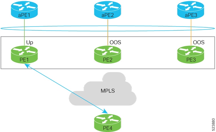
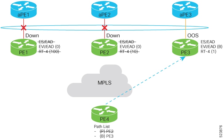
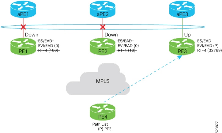
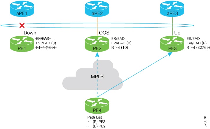
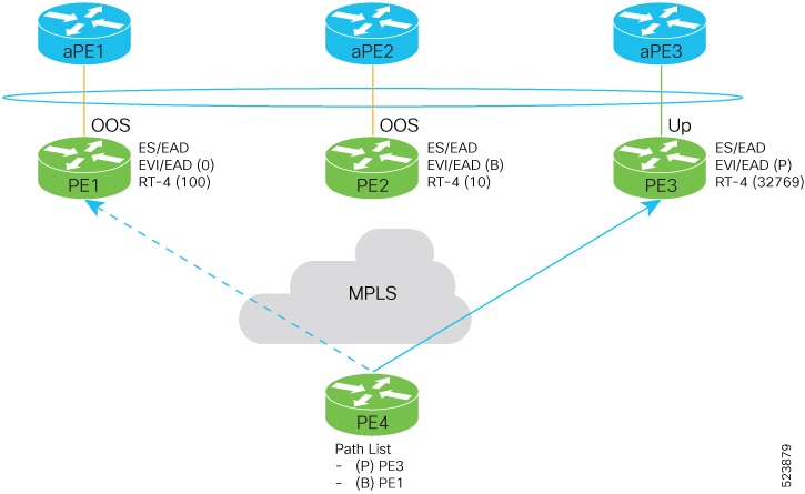
Figure 1. EVPN DF election

These are the stages of EVPN DF election.

  1. Initial traffic flow.
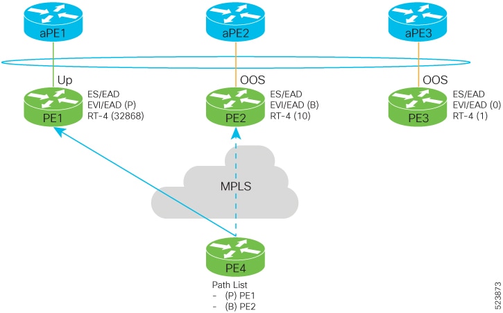
    Figure 2. Traffic flow
    • The aPE1-PE1 interface is active (up), while aPE2-PE2 and aPE3-PE3 interfaces remain out of service (OOS).
    • Traffic from PE4 is forwarded to aPE1 through PE1 because PE1 has the highest configured weight of 100.
    • The highest weight is adjusted by adding 32,768 to the configured value (e.g., PE1’s weight 100 becomes 32,868).
    • The highest weight is advertised with the P-bit (primary), the next highest with the B-bit (backup), and the lowest weight as non-designated forwarder (NDF).
    • When EVPN PE devices have the same weight, traffic forwarding preference is determined by the lowest IP address.
    • Only one PE signals that the Ethernet Segment bundle state is up; all other PEs mark the Ethernet Segment as standby and their bundles as OOS.
    • All PE devices maintain awareness of their peers’ next hops and weights.
  2. Failure and recovery scenarios.
    • The weights configured on EVPN PE devices follow the same order as the protection mechanism on the access side PEs: aPE1, aPE2, then aPE3.
    • The weight hierarchy is PE1 > PE2 > PE3.
    • If this ordering is not maintained, the network will eventually converge, but efficiency will be reduced.
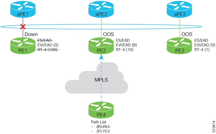
  3. Scenario 1 – aPE1-PE1 interface down
    • PE1 withdraws the EAD/ES route.
    • Traffic is sent through the backup path through PE2.
    • aPE2-PE2 becomes primary with a weight of 32,778 and advertises the P-bit.
    • aPE3-PE3 becomes backup and advertises the B-bit.
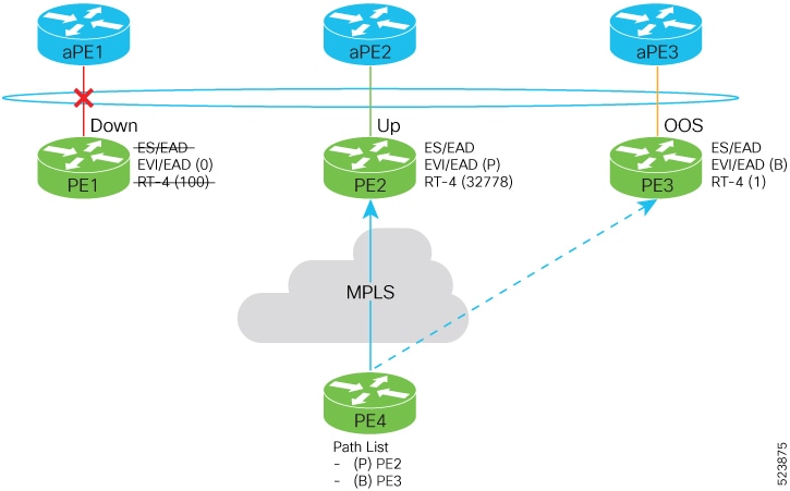
  4. Scenario 2 – aPE2-PE2 interface also down
    • Traffic is sent through aPE3-PE3 link.
    • aPE3-PE3 becomes the primary path with a weight of 32,769.
  5. Scenario 3 – aPE2-PE2 interface recovers
    • aPE3-PE3 remains the primary path.
    • aPE2-PE2 becomes the backup path with a weight of 10.
  6. Scenario 4 – aPE1-PE1 interface recovers
    • aPE3-PE3 remains the primary path with a weight of 32,769.
    • aPE1-PE1 becomes the backup path with a weight of 100.
    • aPE2-PE2 becomes non-designated forwarder (NDF) with a weight of 10.

Result

This process ensures efficient traffic forwarding and redundancy in the EVPN network by precomputing backup paths based on configured weights and interface states, enabling fast failover and recovery while maintaining optimal traffic flow.

Configure EVPN DF election

Configure EVPN DF election using preference-based and access-driven service carving modes, and enable LACP with non-revertive mode on associated aPE devices.

Use this task to set up stable and efficient DF election across multiple PE devices with differentiated weights and access-driven behavior, while supporting link aggregation on aPE devices.

Before you begin

  • Ensure all PE devices are reachable and have consistent Ethernet Segment Identifiers (ESI).

  • Confirm LACP support on bundle interfaces.

Perform these tasks to configure access-driven and preference-based EVPN DF election:

  • Configure EVPN DF election on PE1, PE2, and PE3, with the service carving mode as preference-based and access-driven.

  • Configure LACP on aPE1, aPE2, and aPE3

Procedure


Step 1

Configure EVPN DF election on PE1, PE2, and PE3

Example:

on PE1
Router#configure
Router(config)#evpn
Router(config-evpn)#interface Bundle-Ether1
Router(config-evpn-ac)#ethernet-segment
Router(config-evpn-ac-es)#identifier type 0 01.11.00.00.00.00.00.00.01
Router(config-evpn-ac-es)#load-balancing-mode port-active
Router(config-evpn-ac-es)#service-carving preference-based
Router(config-evpn-ac-es-sc-pref)#weight 100 
Router(config-evpn-ac-es-sc-pref)#access-driven
Router(config-evpn-ac-es-sc-pref)#commit

Example:

on PE2

Example:

Router#configure
Router(config)#evpn
Router(config-evpn)#interface Bundle-Ether1
Router(config-evpn-ac)#ethernet-segment
Router(config-evpn-ac-es)#identifier type 0 01.11.00.00.00.00.00.00.01
Router(config-evpn-ac-es)#load-balancing-mode port-active
Router(config-evpn-ac-es)#service-carving preference-based
Router(config-evpn-ac-es-sc-pref)#weight 10 
Router(config-evpn-ac-es-sc-pref)#access-driven
Router(config-evpn-ac-es-sc-pref)#commit

Example:

on PE3

Example:

Router#configure
Router(config)#evpn
Router(config-evpn)#interface Bundle-Ether1
Router(config-evpn-ac)#ethernet-segment
Router(config-evpn-ac-es)#identifier type 0 01.11.00.00.00.00.00.00.01
Router(config-evpn-ac-es)#load-balancing-mode port-active
Router(config-evpn-ac-es)#service-carving preference-based
Router(config-evpn-ac-es-sc-pref)#weight 1 
Router(config-evpn-ac-es-sc-pref)#access-driven
Router(config-evpn-ac-es-sc-pref)#commit

Step 2

Configure LACP on aPE1, aPE2, and aPE3.

Example:

on aPE1

Example:

Router#configure
Router(config)#interface Bundle-Ether 1
Router(config-if)#lacp non-revertive
Router(config-if)#bundle maximum-active links 1 hot-standby
Router(config-if)#exit
Router(config-if)#interface GigabitEthernet0/0/0/40
Router(config-if)bundle id 10 mode active
Router(config-if)bundle port-priority 10000
Router(config-if)description Connection to PE1
Router(config-if)commit

Example:

on aPE2
Router#configure
Router(config)#interface Bundle-Ether 1
Router(config-if)#lacp non-revertive
Router(config-if)#bundle maximum-active links 1 hot-standby
Router(config-if)#exit
Router(config-if)#interface GigabitEthernet0/0/0/39
Router(config-if)bundle id 10 mode active
Router(config-if)bundle port-priority 20000
Router(config-if)description Connection to PE2
Router(config-if)commit

Example:

on aPE2
Router#configure
Router(config)#interface Bundle-Ether 1
Router(config-if)#lacp non-revertive
Router(config-if)#bundle maximum-active links 1 hot-standby
Router(config-if)#exit
Router(config-if)#interface GigabitEthernet0/0/0/38
Router(config-if)bundle id 10 mode active
Router(config-if)bundle port-priority 30000
Router(config-if)description Connection to PE3
Router(config-if)commit

Step 3

Running configuration of EVPN DF election.

Example:


/* PE1 Configuration */
evpn
 interface Bundle-Ether 1
  ethernet-segment
   identifier type 0 01.11.00.00.00.00.00.00.01
    load-balancing-mode port-active
    service-carving preference-based
    weight 100
    access-driven
   !
 !  

/* PE2 Configuration */
evpn
 interface Bundle-Ether 1
  ethernet-segment
   identifier type 0 01.11.00.00.00.00.00.00.01
    load-balancing-mode port-active
    service-carving preference-based
    weight 10
    access-driven
   !
 !  

/* PE3 Configuration */
evpn
 interface Bundle-Ether 1
  ethernet-segment
   identifier type 0 01.11.00.00.00.00.00.00.01
    load-balancing-mode port-active
    service-carving preference-based
    weight 1
    access-driven
   !
 !  

/* aPE1 Configuration */

interface Bundle-Ether 1
 lacp non-revertive
  bundle maximum-active links 1 hot-standby
interface GigabitEthernet0/0/0/40
 bundle id 10 mode active
 bundle port-priority 10000
 description Connection to PE1
!

/* aPE2 Configuration */

interface Bundle-Ether 1
 lacp non-revertive
  bundle maximum-active links 1 hot-standby
interface GigabitEthernet0/0/0/39
 bundle id 10 mode active
 bundle port-priority 20000
 description Connection to PE2
!

/* aPE3 Configuration */

interface Bundle-Ether 1
 lacp non-revertive
  bundle maximum-active links 1 hot-standby
interface GigabitEthernet0/0/0/40
 bundle id 10 mode active
 bundle port-priority 30000
 description Connection to PE3
!

Step 4

Use the show evpn ethernet-segment detail to verify that you have successfully configured EVPN DF election.

Example:


Router#show evpn ethernet-segment detail
Ethernet Segment Id      Interface                          Nexthops            
------------------------ ---------------------------------- --------------------
0001.0001.0001.1b01.001b BE1                                192.168.0.1
                                                            192.168.0.3
  ES to BGP Gates   : Ready
  ES to L2FIB Gates : Ready
  Main port         :
     Interface name : Bundle-Ether1
     Interface MAC  : 02ef.af8d.8008
     IfHandle       : 0x00004190
     State          : Up
     Redundancy     : Active
  ESI type          : 0
     Value          : 01.0001.0001.1b01.001b
  ES Import RT      : 0100.0100.011b (from ESI)
  Source MAC        : 0000.0000.0000 (N/A)
  Topology          :
     Operational    : MH
     Configured     : Port-Active 
  Service Carving   : Preferential
     Multicast      : Disabled
  Convergence       : 
  Peering Details   : 2 Nexthops
     192.168.0.1 [PREF:P:d6ce:T] >> Weight in hexadecimal
     192.168.0.3 [PREF:P:457]
  Service Carving Synchronization:
     Mode           : NONE
     Peer Updates   :
  Service Carving Results:
     Forwarders     : 3
     Elected        : 3
     Not Elected    : 0
  EVPN-VPWS Service Carving Results:
     Primary        : 1
     Backup         : 0
     Non-DF         : 0
  MAC Flushing mode : STP-TCN
  Peering timer     : 3 sec [not running]
  Recovery timer    : 30 sec [not running]
  Carving timer     : 0 sec [not running]
  Local SHG label   : 28384
  Remote SHG labels : 0
  Access signal mode: Bundle OOS (Default)

Highest random weight mode for EVPN DF election

A Highest Random Weight (HRW) mode for EVPN DF election is a capability that

  • provides optimal load distribution for DF election

  • ensures redundancy, enables fast access, and

  • guarantees nondisruptive service for an Ethernet Segment (ES) regardless of the state of a peer DF.

DF election weight calculation

The DF election is determined by calculating weights for each router on the Ethernet segment. The router with the highest weight is selected as the DF, while the router with the next highest weight becomes the backup designated forwarder (BDF).

The weight is computed using the following formula:

Wrand(v, Si) = (1103515245 × ((1103515245 × Si + 12345) XOR D(v)) + 12345) mod 2³¹

where:

  • Si: IP address of router i

  • v: Ethernet Virtual Instance (EVI)

  • D(v): 31-bit digest, specifically the CRC-32 checksum of v

This calculation ensures a unique and deterministic weight assignment based on the router’s IP address and the EVI, facilitating the election of the DF and BDF roles.

Designated forwarder election algorithm

The DF election algorithm determines which PE device forwards traffic for a multihomed Ethernet segment. It uses a mathematical function called “service carving,” which combines the ESI and EVI, as described in RFC 7432.

Key points about the algorithm:

  • The election is based on an ordinal value derived from a modulus calculation involving the number of peers and the EVI.

  • This modulus calculation mode can perform poorly when Ethernet tags are all even or all odd.

  • In scenarios where an Ethernet Segment (ES) is multihomed to two PEs, all VLANs may select the same PE as the DF.

  • Consequently, one PE may never be elected as the DF, resulting in a non-optimal distribution of forwarding responsibilities.

Benefits of highest random weight mode over modulus mode in DF election

The HRW mode of DF election offers several advantages compared to the modulus mode:

  • Equal distribution of DF election across PEs: The DF election for each VLAN is evenly distributed among the PEs, ensuring balanced load sharing.

  • Stability during PE failures: If a PE that is neither a DF nor a BDF hosting VLANs on a given ES goes down or loses connection to the ES, it does not trigger a reassignment of DF and BDF roles to other PEs. This behavior reduces unnecessary computation during connection flaps.

  • Minimized service disruption: HRW mode avoids the service interruptions that are common with the modulus-based DF election algorithm.

  • Redundant connectivity through BDF: The BDF provides backup connectivity, ensuring no traffic disruption occurs when a DF fails. In such cases, the BDF automatically assumes the DF role.

Configure highest random weight mode for EVPN DF election

Enable the HRW mode for DF election in EVPN to optimize forwarding decisions based on a hashing algorithm, improving load distribution and redundancy.

Procedure

Step 1

Configure HRW mode for EVPN DF election.

Example:

Router# configure
Router(config)#evpn
Router(config-evpn)#interface Bundle-Ether 23
Router(config-evpn-ac)#ethernet-segment
Router(config-evpn-ac-es)#service-carving hrw
Router(config-evpn-ac-es)#commit

Step 2

Running configuration of HRW mode for DF election.

Example:

configure
 evpn
  interface Bundle-Ether 23
   ethernet-segment
    service-carving hrw
   !
  !
 !

Step 3

Use the show evpn ethernet-segment interface bundleEther 23 carving detail command to verify that you have configured HRW mode of DF election.

Example:

Router#show evpn ethernet-segment interface bundleEther 23 carving detail
Ethernet Segment Id      Interface                          Nexthops            
------------------------ ---------------------------------- --------------------
0011.1111.1111.1111.1111 Gi0/2/0/0                          192.168.0.2
                                                            192.168.0.3
  ES to BGP Gates   : Ready
  ES to L2FIB Gates : Ready
  Main port         :
     Interface name : GigabitEthernet0/2/0/0
     Interface MAC  : 02db.c740.ca4e
     IfHandle       : 0x01000060
     State          : Up
     Redundancy     : Not Defined
  ESI type          : 0
     Value          : 11.1111.1111.1111.1111
  ES Import RT      : 0011.0011.0011 (Local)
  Source MAC        : 0000.0000.0000 (N/A)
  Topology          :
     Operational    : MH, Single-active
     Configured     : Single-active (AApS) (default)
  Service Carving   : HRW    -> Operation mode of carving
  Peering Details   : 192.168.0.2[HRW:P:00] 192.168.0.3[HRW:P:00] -> Carving capability as advertised by peers
  Service Carving Results:
     Forwarders     : 1
     Permanent      : 0
     Elected        : 0
     Not Elected    : 1
  MAC Flushing mode : STP-TCN
  Peering timer     : 3 sec [not running]
  Recovery timer    : 30 sec [not running]
  Carving timer     : 0 sec [not running]
  Local SHG label   : 28109
  Remote SHG labels : 1
              24016 : nexthop 192.168.0.3

EVPN non-revertive DF election

A non-revertive mode of DF election is a network configuration mode that

  • adjusts the weight of PE devices so that the PE that became the designated forwarder during a link failure remains the designated forwarder after the link recovers

  • prevents traffic disruption during DF re-election and service re-carving, and

  • avoids triggering service re-carving after recovery.

Table 5. Feature History Table

Feature Name

Release Information

Feature Description

EVPN non-revertive DF election

Release 24.4.1

Introduced in this release on: Fixed Systems (8700) (select variants only*)

* The EVPN Non-Revertive Designated Forwarder Election functionality is now extended to the Cisco 8712-MOD-M routers.

EVPN non-revertive DF election

Release 24.3.1

Introduced in this release on: Fixed Systems (8200, 8700); Modular Systems (8800 [LC ASIC: P100]) (select variants only*)

* The EVPN Non-Revertive Designated Forwarder Election functionality is now extended to:

  • 8212-48FH-M

  • 8711-32FH-M

  • 88-LC1-52Y8H-EM

  • 88-LC1-12TH24FH-E

EVPN non-revertive DF election

Release 24.2.11

Introduced in this release on: Modular Systems (8800 [LC ASIC: P100]) (select variants only*)

In a preference-based Designated Forwarder (DF) election, non-revertive mode prevents the traffic disruption that occurs during the recovery of a node in a port-active multihoming network.

While recovering from a link failure, an EVPN ethernet-segment (ES) performs DF re-election and re-carves the services among the multihomed nodes, which causes traffic interruption and interface flapping, leading to traffic loss. In the non-revertive mode, the EVPN ES does not re-carve the services after the recovery, thus avoiding the traffic disruption.

The feature introduces these changes:

CLI:

YANG Data Model:

  • Cisco-IOS-XR-evpn-oper.yang

  • Cisco-IOS-XR-l2vpn-cfg.yang

(see GitHub, YANG Data Models Navigator)

* This feature is supported only on routers with the 88-LC1-36EH line cards.

Non-revertive mode to minimize traffic interruption during DF re-election

During link recovery, the re-election of the DF and the re-carving of services cause traffic interruptions and loss. This problem worsens when an Ethernet Segment hosts multiple services because the time required for service re-carving and transferring the DF role to the Provider Edge (PE) with the highest weight prolongs traffic disruption.

The non-revertive mode addresses this issue by preventing the DF role from reverting to the original PE with the highest weight after failure recovery. Instead, it maintains the current DF, which reduces service interruptions and traffic loss during recovery. This approach enhances network stability and ensures better service continuity.

Key points:

  • DF election is preference-based, selecting the PE with the highest weight as DF.

  • Link failure triggers DF as DF.

  • Link failure triggers DF re-election, causing traffic interruption.

  • Recovery triggers another re-election and service re-carving, increasing the risk of traffic loss.

  • Non-revertive mode avoids reverting the DF role to the original PE after recovery.

  • This mode reduces traffic interruption and improves service continuity during failover and recovery.

To return to revertive mode, the network resumes the DF election and service carving processes. This transition allows the DF role to revert to the PE with the highest preference, restoring the default behavior.

  • Using the revert timer: Configure a timer with the revert command that starts during node recovery. When this timer expires, revertive mode activates, triggering the DF election. This delay helps prevent immediate traffic disruption by postponing the election, allowing the PE with the highest preference to become the DF smoothly.

  • Disabling non-revertive mode: Use the l2vpn evpn ethernet-segment interface revert command to disable non-revertive mode. This action immediately triggers DF election and service carving. If a revert timer was previously set, it is canceled upon disabling non-revertive mode.

Restrictions for EVPN non-revertive DF election

Use non-reverting mode of EVPN DF election only in these scenarios:

  • When performing preference-based DF election.

  • On physical and bundle interfaces.

  • In EVPN port-active multihoming mode.

Do not use non-reverting mode of EVPN DF election in these scenarios:

  • When using access-driven DF election.

  • On virtual interfaces such as virtual Ethernet segment (vES), network virtualization endpoint (NVE), and pseudowire headend (PWHE).

  • When employing segment routing over IPv6 (SRv6).

Configure EVPN non-revertive DF election

Enable non-revertive DF election to prevent traffic disruption during link recovery in EVPN.

In EVPN networks, the DF election determines which PE device forwards traffic for a multi-homed Ethernet segment. By default, DF election reverts to the highest-weight PE after link recovery, which can cause traffic disruption. Configuring non-revertive mode maintains the current DF to avoid this disruption.

Before you begin

It is recommended to configure the non-revertive mode of DF election on all the nodes in the network.

  1. Configure Ethernet segment in port-active load-balancing mode on peering PEs for a specific interface, using the load-balancing-mode port-active command.

  2. Configure the service carving mode as preference-based using the service-carving preference-based command. The DF election happens based on the highest preference, that is the weight of the PE.

  3. Configure the non-revertive mode of DF election using the non-revertive command, to enable the non-revertive mode on the PEs.

  4. Configure the PE devices with different weights, using the weight command.

Procedure

Step 1

Configure non-revertive mode.

In this example, PE1 and PE2 are configured with a weight of 100 and 10 respectively.

  • After the DF election, PE1 is selected as the DF.

  • When there is a link failure, PE1 goes down, and the next PE with the highest weight, PE2, becomes the DF.

  • By default, the DF election happens during the recovery, and PEl becomes the DF again. Transferring the DF role from PE2 to PE1 leads to traffic disruption.

  • When the non-revertive mode is enabled, the weight of the PE1 is adjusted so that PE2 remains the DF. This prevents the traffic disruption incurred due to the DF election.

  1. Configure non-revertive mode on PE1.

    Example:
    Router# configure
    Router(config)# evpn
    Router(config-evpn)# interface Bundle-Ether1
    Router(config-evpn-ac)# ethernet-segment
    Router(config-evpn-ac-es)# identifier type 0 01.11.00.00.00.00.00.00.01
    Router(config-evpn-ac-es)# load-balancing-mode port-active
    Router(config-evpn-ac-es)# service-carving preference-based
    Router(config-evpn-ac-es-sc-pref)# non-revertive
    Router(config-evpn-ac-es-sc-pref)# weight 100 
    Router(config-evpn-ac-es-sc-pref)# commit
  2. Configure non-revertive mode on PE2.

    Example:
    Router# configure
    Router(config)# evpn
    Router(config-evpn)# interface Bundle-Ether1
    Router(config-evpn-ac)# ethernet-segment
    Router(config-evpn-ac-es)# identifier type 0 01.11.00.00.00.00.00.00.01
    Router(config-evpn-ac-es)# load-balancing-mode port-active
    Router(config-evpn-ac-es)# service-carving preference-based
    Router(config-evpn-ac-es-sc-pref)# non-revertive
    Router(config-evpn-ac-es-sc-pref)# weight 10 
    Router(config-evpn-ac-es-sc-pref)# commit

Step 2

Running configuration of EVPN non-revertive mode DF election.

Example:
evpn
 interface Bundle-Ether1
  ethernet-segment
   identifier type 0 01.11.00.00.00.00.00.00.01
   load-balancing-mode port-active
   service-carving preference-based
    non-revertive    
    weight 100
   !
evpn
 interface Bundle-Ether1
  ethernet-segment
   identifier type 0 01.11.00.00.00.00.00.00.01
   load-balancing-mode port-active
   service-carving preference-based
    non-revertive    
    weight 10

Step 3

Use the show evpn ethernet-segment interface Bundle-Ether 1 private command to verify that non-revertive mode is enabled.

Example:
Router# show evpn ethernet-segment interface Bundle-Ether 1 private

…
  Topology          :
     Operational    : SH
     Configured     : Port-Active
  Service Carving   : Preferential
     Config Weight  : 100
     Oper Weight    : 100
     Non-Revertive  : Enabled, Active
     Access Driven  : Disabled
     Multicast      : Disabled
  Convergence       : 
  Peering Details   : 2 Nexthops
     192.168.0.1 [PREF:DP:7fff:T][1]
     192.168.0.3 [PREF:DP:7fff:T][2]

Configure to return to revertive mode

Restore the default revertive mode behavior in EVPN after a link failure recovery.

In non-revertive mode, the DF election does not occur during recovery from a link failure. To revert to the default behavior where DF election happens, configure the revert timer.

Procedure


Step 1

Configure non-revertive mode on an interface and configure revert timer on the interface.

When you configure a revert timer on the PEs enabled with non-revertive mode, the timer starts after the nodes have recovered from link failure. After the timer expires, the PEs return to the revertive mode and DF election happens in the network. The timer is configured in seconds.

Example:

outer# configure
Router(config)# evpn
Router(config-evpn)# interface Bundle-Ether1
Router(config-evpn-ac)# ethernet-segment
Router(config-evpn-ac-es)# identifier type 0 01.11.00.00.00.00.00.00.01
Router(config-evpn-ac-es)# load-balancing-mode port-active
Router(config-evpn-ac-es)# service-carving preference-based
Router(config-evpn-ac-es-sc-pref)# non-revertive
Router(config-evpn-ac-es-sc-pref)# weight 100 
Router(config-evpn-ac-es-sc-pref)# exit
Router(config-evpn-ac-es)# exit
Router(config-evpn-ac)# timers
Router(config-evpn-ac-timers)# revert 300
Router(config-evpn-ac-es)# commit

You can also configure the revert timer globally.

Router(config)# evpn
Router(config-evpn)# timers
Router(config-evpn-timers)# revert 300
Router(config-evpn-timers)# commit

Step 2

Running configuration of return to revertive mode.

Example:

Revert timer configuration on an interface.


evpn 
 interface Bundle-Ether1 
  ethernet-segment
   identifier type 0 01.11.00.00.00.00.00.00.01 
   load-balancing-mode port-active 
   service-carving preference-based 
    non-revertive 
  ! 
   timers 
    revert 300

Global configuration of revert timer.


evpn 
  timers 
   revert 300

Step 3

Use the show evpn ethernet-segment interface Bundle-Ether 1 private command to verify that non-revertive mode is enabled along with the configured revert timer.

Example:

Router# show evpn ethernet-segment interface Bundle-Ether 1 private

 …
  Topology          :
     Operational    : SH
     Configured     : Port-Active
  Service Carving   : Preferential
     Config Weight  : 100
     Oper Weight    : 100
     Non-Revertive  : Enabled, Active
     Access Driven  : Disabled
     SRG Driven     : Disabled
     Multicast      : Disabled
  Convergence       : 
  Peering Details   : 0 Nexthops
  Service Carving Synchronization:
     Mode           : NONE
     Peer Updates   :
  Service Carving Results:
     Forwarders     : 0
     Elected        : 0
     Not Elected    : 0
  EVPN-VPWS Service Carving Results:
     Primary        : 0
     Backup         : 0
     Non-DF         : 0
  MAC Flush msg     : STP-TCN
  Peering timer     : 3 sec [not running]
  Recovery timer    : 30 sec [not running]
  Carving timer     : 0 sec [not running]
  Revert timer      : 300 sec [not running]
  HRW Reset timer   : 5 sec [not running]
  AC Debounce timer : 3000 msec [not running]

In this example, the revert timer has expired and the non-revertive mode is inactive.

Router# show evpn ethernet-segment interface Bundle-Ether 1 private

 …
  Topology          :
     Operational    : SH
     Configured     : Port-Active
  Service Carving   : Preferential
     Config Weight  : 100
     Oper Weight    : 100
     Non-Revertive  : Enabled, Inactive
     Access Driven  : Disabled
     SRG Driven     : Disabled
     Multicast      : Disabled
  Convergence       : 
  Peering Details   : 0 Nexthops
  Service Carving Synchronization:
     Mode           : NONE
     Peer Updates   :
  Service Carving Results:
     Forwarders     : 0
     Elected        : 0
     Not Elected    : 0
  EVPN-VPWS Service Carving Results:
     Primary        : 0
     Backup         : 0
     Non-DF         : 0
  MAC Flush msg     : STP-TCN
  Peering timer     : 3 sec [not running]
  Recovery timer    : 30 sec [not running]
  Carving timer     : 0 sec [not running]
  Revert timer      : 0 sec [not running]
  HRW Reset timer   : 5 sec [not running]
  AC Debounce timer : 3000 msec [not running]

The PE devices return to revertive mode after the revert timer expires, restoring the default DF election behavior during link recovery.

Disable non-revertive mode

Disable the non-revertive behavior on an Ethernet segment interface to cancel the revert timer and trigger a new DF election in the network.

Use this task when you need to stop the non-revertive mode on an Ethernet segment interface, causing the network to perform a fresh DF election.

Procedure


Disable non-revertive mode on the specified Ethernet segment interface.

Example:

Router# l2vpn evpn ethernet-segment interface Bundle-Ether1 revert

This command cancels the revert timer if it is configured and initiates a new DF election in the network.


The non-revertive mode is disabled, the revert timer is cancelled, and the network performs a new DF election.